 P. S. Effertz
 W. S. de Carvalho
 R. P. M. Guimarães
 S. T. Amancio-Filho
- BMK Endowed Professorship for Aviation, Institute of Materials Science, Joining and Forming, Graz University of Technology, Graz, Austria
The Refill Friction Stir Spot Welding is an innovative spot like solid state process befitting of overlap joint configurations of similar and dissimilar materials. This process caught the interest and is rapidly growing in the aerospace sector due to its potential to substitute traditional mechanical fasteners, surpassing their mechanical performance while maintaining the so desired lightweight “rationale.” In the current study, process parameters, namely plunge depth, plunge time and rotational speed, are optimized in order to obtain the highest Ultimate Lap Shear Force (ULSF) of 2024-T3 Aluminum Alloy similar joints. The optimization campaign was carried out using a second order multivariate polynomial regression machine learning (ML) algorithm. The trained ML model was able to generalize and accurately predict the Ultimate Lap Shear Force on the holdout set, having a
1 Introduction
Refill Friction Stir Spot Welding (RFSSW) is a solid-state welding process (Schilling and dos Santos, 2004) suitable for spot joining of lightweight metallic alloys [e.g., Aluminum (Amancio-Filho et al., 2011a; Carvalho et al., 2021) and Magnesium alloys (Schilling and dos Santos, 2004; Amancio-Filho et al., 2011a; Carvalho et al., 2021)] as well as polymer and composite materials (Henrique et al., 2012; Junior et al., 2014; Gonçalves et al., 2016). Friction Spot Joining (FSpJ) (AmancioFilho and dos Santos, 2013) is a further development of the RFSSW, which is applied to produce metal-polymer or metal-composite hybrid joints (Goushegir and Amancio-Filho, 2018). Both processes have been developed in the early 2000s as alternatives for mechanical fastenings, adhesives and traditional fusion welding techniques and their main advantages are: low energy consumption (related with the high efficiency of mechanical energy transformation into frictional heat), superior mechanical properties (Manente et al., 2019; André et al., 2020; Goushegir et al., 2020), good corrosion resistance (André et al., 2019; Bouali et al., 2021)—due to absence of rivets, screws and keyhole, near-flush finish and hermetic weld/joint sealing, etc.
The key element of these processes is a non-consumable tool with three independent cylindrical and concentric moving parts comprising of a stationary clamping ring, rotating shoulder and probe. Both techniques are performed in four different steps as shown in Figure 1 for the RFFSW. Initially, the clamping ring holds the sheets firmly against a backing plate and constrains the material flow during the process and, simultaneously, probe and shoulder start to rotate with the same rotational speed and in the same direction (Figure 1A). The probe and the shoulder then move in the opposite direction–i.e., one is plunged into the material while the other retracts; therefore, creating a cavity where the plasticized material is accommodated inside the tool. The rotating shoulder introduces plastic deformation and generates frictional heating (Figure 1B). After reaching the pre-set plunge depth, both shoulder and probe can remain rotating in this position for a specific period or immediately return to their initial position, forcing the displaced material to completely refill the keyhole (Figure 1C). Finally, the tool rotation is ceased and the tool is withdrawn from the joint leaving a flat surface with minimum material loss (“pull-out”). According to Shen et al. (2015), a probe-plunge process variant can also be performed, however the mechanical performance reached by joints produced through the shoulder-plunge variant are higher due to the larger welded area. The main difference between the RFSSW and FSpJ techniques lays on the tool plunging step. While in the RFSSW of metals and polymers, the shoulder (or probe) will normally reach and stir the bottom welding part, thereby inducing a better material mix in between the welding parts, the FSpJ tool plunging takes place only in the upper metallic part; this will hinder the damaging of the fiber-reinforcement for composites, or the formation of voids in the metal (Amancio-Filho et al., 2011b).
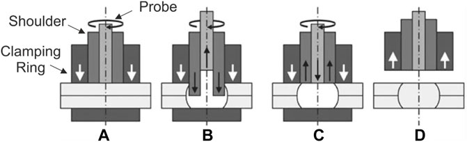
FIGURE 1. Illustration of RFSSW stages for the shoulder-plunge variant: (A) clamping and tool rotation; (B) shoulder plunge and probe retraction; (C) tool back to surface level and (D) tool removal (Reprinted with permission from the publisher under a Creative Common license) (Campanelli et al., 2012).
Several publications are available in literature investigating the RFSSW/FSpJ for similar, dissimilar material combinations of metals and composites (Amancio-Filho et al., 2011a; Amancio-Filho et al., 2011b; Rosendo et al., 2011; Shen et al., 2013; Shen et al., 2014; Suhuddin et al., 2014; Chen et al., 2015; Esteves et al., 2015; Dong et al., 2016; Shen et al., 2016) Furthermore, considerable effort has been carried out in assessing the influence of process parameters on the mechanical and microstructural properties of the joints using several statistical tools, such as Design of Experiments (DoE), Survival Analysis, etc. While investigating the influence of parameters on AA7050-T76 similar RFSSW joints, Effertz et al. (Effertz et al., 2017) conducted an optimization study based on Taguchi orthogonal DoE to yield the parameter combination that maximised Lap Shear Force. They also concluded that PD was the most significant predictor for LSF. The same author (Effertz et al., 2016) investigated the fatigue failure prediction of AA7050-T76 using statistical reliability engineering, namely Weibull Survival Analysis that provided outstanding Time to Failure (TTF) predictions.
Despite the thoroughly documented capabilities of the aforementioned statistical tools, Machine Learning (ML) and Deep Learning (DL) have been gradually gaining researchers attention for solid-state joining process optimisation campaigns. Verma et al. (2018) used three ML algorithms, i.e., Support Vector Regression (SVR), Gaussian Process Regression (GPR) and Multi-Linear Regression (MLR), to predict the ultimate tensile strength of Friction Stir Welded AA6082. The authors concluded that RBF kernel based GPR regression technique works well in comparison to SVM and MLR regression approaches for the studied dataset. In the work of Hartl et al. (2020) the aim was to use reinforcement learning and Bayesian optimisation approaches to determine the most appropriate settings for the welding speed and the rotational speed of the tool. Although both approaches were able to solve the problem, Bayesian optimization proved to be more efficient. Regarding RFSSW, Bock et al. (2021) used different regression analysis algorithms, such as linear regression, decision trees and random forests, to assess the influence of rotational speed, plunge depth and speed on cross tensile strength of AA7075. The authors used a previously established Box-Behnken DoE as dataset and concluded that for that specific dataset Decision Tree Regression (DTR) was the model yielding the best predictive ability.
The number of publication making use of ML techniques applied to solid state processes is still limited and requires extensive research. The present work aims to contribute to the knowledge gap related to the application of ML algorithms to optimise RFSSW, as a relevant alternative to the already well reported DoE. Hence, in this study, RFSSW parameters, namely Rotational Speed (RS), Welding Time (WT) and Plunge Depth (PD) were investigated using an already existent dataset from a previous work (Tier et al., 2009) on AA2024-T3. A second order MPR algorithm was used to develop a model capable of predicting the Ultimate Lap Shear Force (ULSF) and obtain an optimised condition yielding its maximum.
2 Materials and Methods
The details of the investigation conducted by Tier et al. (2009) on 2 mm-thick Alclad AA2024-T3 similar overlap joints are briefly reviewed, as this experimental dataset represents the basis for the ML-algorithm herein. Additionally, equipment and methods are underlined as part of the joints produced to validate the model’s prediction for an optimized parameter combination.
2.1 Data Frame
A sensitivity analysis was performed to identify the relationships between process parameters and ULSF of overlapped joints. No dwell time was considered, thus both probe and plunge have been retracted as soon as the required plunge depth has been achieved.
The experimental data according to Tier et al.(Tier et al., 2009) is shown in Table 1, from which the column related to Plunge Rate was disregarded in this work, as it can be obtained by linear combination of PD and WT (i.e. the quotient between PD and WT). Statistical description of the data is provided in Table 2. Since the regression problem is solved using Ordinary Least Squares (OLS), it is imperative that all factors are linearly independent to ensure the normal matrix is invertible. The formulation presented in Section 3 will make this assertion clear.
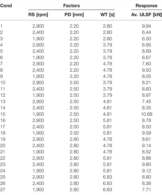
TABLE 1. Experimental matrix, according to Tier et al. (2009), used for the herein ML-algorithm.
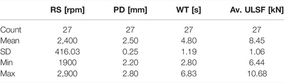
TABLE 2. Statistical description of the data.
(Figure 2 highlights the correlation between the input and output parameters. According to the heatmap the value 0.71 suggests a high correlation between WT and PD, whereas the remainder features and output are weakly correlated.
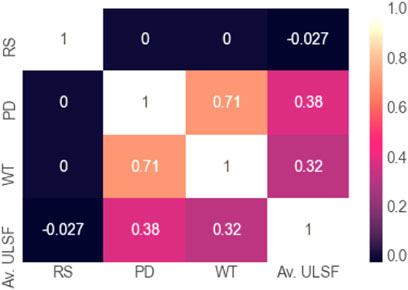
FIGURE 2. Heatmap of the data.
2.2 Experimental Procedure
2-mm thick AA2024-T3 rolled sheets were applied to produce similar overlap joints for validation of the ML derived models. The nominal chemical composition of the alloy is presented in Table 3. It should be noted that there are marginal differences in chemical composition between the alloy used in this work and the one from (Tier et al., 2009). Moreover, non-Alclad AA2024-T3 was used for this investigation. However, quasi-identical mechanical properties are to be expected according to (Anderson et al., 2019).

TABLE 3. Nominal chemical composition of AA2024-T3 (wt%).
Spot welds were produced with two 100 mm × 25.4 mm plates and an overlap length of 25.4 mm, as shown in Figure 3. The welding process was performed using an RPS 100 RFSSW equipment (Harms-Wende, Germany) with a standard welding tool made of H13 tool steel alloy provided by the manufacturer. The diameters of the clamping ring, shoulder and probe tool components were 18, 9 and 6 mm, respectively. Lap shear testing was performed using a Zwick-Roell universal testing machine equipped with a 100 kN load cell, with constant crosshead speed of 2 mm/min at room temperature in accordance with DIN ISO 14273 standard.
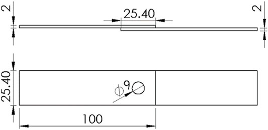
FIGURE 3. Configuration and dimensions of the joints used for lap shear test (in mm).
2.3 Microstructural Characterization
The AA2024-T4 joints were cross-sectioned by a precision saw and embedded, subsequently being metallographically prepared by conventional methods. In order to reveal the microstructure electrochemical etching was employed, by which the samples were immersed in Barker’s reagent (5 ml HBF4, 200 ml H2O) and subjected to 25 V during 60 s in a Struers LectroPol (Struers, Germany). Light optical microscopy was performed in bright field aiming to reveal joint features. In addition, by making use of polarized light it was possible to reveal in detail grain size and orientation in different zones, contributing to enlighten the effect of the processing on the material.
2.4 Polynomial Regression Formulation
The polynomial regression ML algorithm was implemented using package Scikit-learn to capture the non-linear dependencies between different the Multiple Regressor Variables or parameters. The generic form of the model over features
where
Equation 1 can be expressed in matrix form in terms of a design matrix
which when using pure matrix notation is written as:
The vector of estimated polynomial regression coefficients is obtained using Ordinary Least Squares (OLS) estimation, thus:
The matrix
The training data was scaled to ensure all regressors are the same order of magnitude, contributing equally to the result and aiding on the interpretability of their influence. Hence, standardization was performed to ensure standard normally distributed data
3 Results and Discussion
This section highlights the equation modelling the predicted ULSF, as well as a thorough analysis of the statistical importance of each feature and their interactions. The quality of the model evaluated by comparing predicted and ground truth via validation experiments. Finally, the microstructure yielded by the best condition is analysed.
3.1 Polynomial Regression Model
To train a model that can adequately fit the data, but also generalizes well for “unseen” observations, a suitable train/test split must be specified. For this problem, due to the low amount of data available, a sensitivity analysis was conducted, from which a train/test split of 85% and 15% was considered, respectively. The data points for holdout/test set were randomly selected. The trained model equation for predicting the ULSF is as follows, expressed with for standardized units:
where
The coefficients of Equation 6 provide valuable interpretative information on the effect that parameters and their interactions have on the response, visually represented in Figure 4. Hence, it is apparent that the quadratic features WT2, RS2 and PD2 influence prominently the ULSF, i.e. due to the concave-downward nature of such features, low and high values of WT, RS and PD will affect more negatively the response. This is coherent with physical underpinnings of the process, since WT, RS and PD are intimately related to the amount of heat input given to the joint, thence its quality, as reported by Esteves et al. (Esteves et al., 2015).
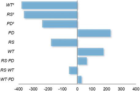
FIGURE 4. MPR coefficients as feature importance scores.
Specifically, the short WT does not allow for sufficient heat to flow from the tooling to the material promoting viscoplastic flow and dynamic recrystallisation as reported in (Effertz et al., 2017). On the other hand, long WT is associated to higher temperature and heat input, promoting grain growth and possible precipitate segregation, typical phenomena observed for the process (Effertz et al., 2016). The same reasoning established for short WT applies to low RS, as not enough shear friction resulting in heat is being generated between tool and material. Contrastingly, the detrimental effect for higher values of RS might be explained by slip between the plunge and material, ensuing insufficient heat input to the joint. This behaviour has been reported for similar friction-based welding processes (Amancio-Filho et al., 2011a; Rosendo et al., 2011; Shen et al., 2014; Shen et al., 2015). Short PD has a negative display on ULSF, as the plunge is unable to promote the mechanical mixing of the overlapped sheets; whereas a long PD translates in the weakening of the lower part of the weld by the plunge in the second stage of welding (Kluz et al., 2019).
Although on a lower level, the linear features also have a significant contribution to the response, with PD and WT signifying an improvement, and RS a deterioration to ULSF. The first-order interactions had the lowest influence on the ULSF.
The performance of the model on the test set has proven to be very satisfactory, with the highest error being 7.9%, as summarized in Table 4. In addition, the statistical score was computed in terms coefficient of determination
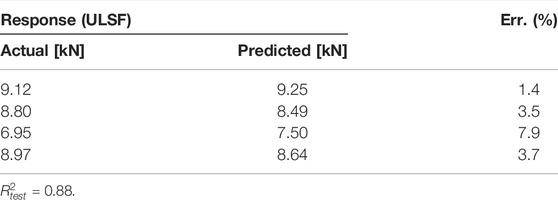
TABLE 4. Actual vs. Predicted ULSF on the test set.
3.2 Prediction for the Optimum Parameters
Having established a working MPR model, the parameter combination that yields the maximum ULSF can be computed. Figure 5 shows the Response Surface Method (RSM) plots relating the process parameters along with the response. Colour coded projection lines and contour plots were included to better visualise the response evolution. The transition from dark blue to dark orange corresponds to the increase of a specific quantity from low to high, respectively. Observing the plots, the point for which the response
where from Equation 6,
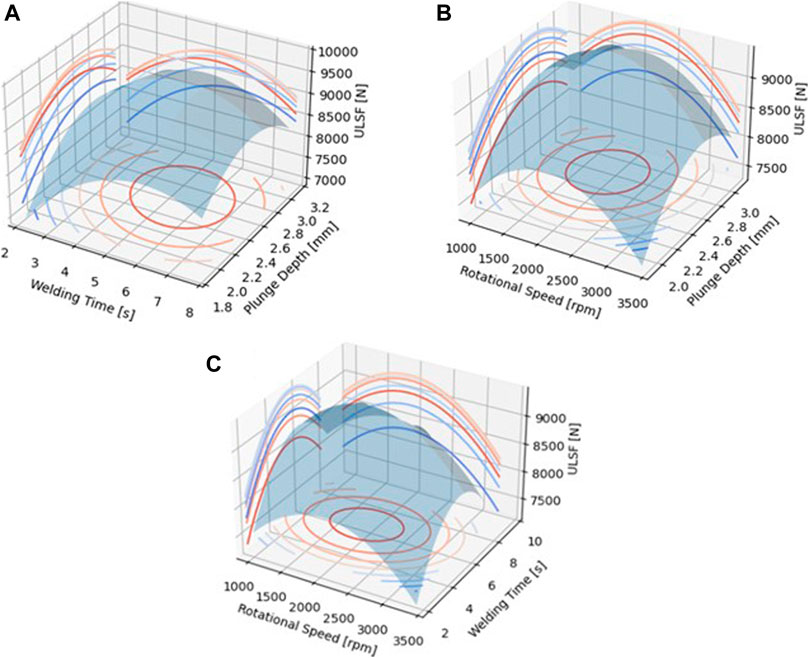
FIGURE 5. Response surface plots on the influence of (A) WT—PD, (B) RS—PD, and (C) RS—WT on the ULSF.
From Equation 7 the standardised stationary vector
where
3.3 Model Validation
The generalisation performance of a learning method relates to its prediction capability on independent test data. Assessment of this performance guides the choice of learning method or model and gives a measure of the quality of the ultimately chosen model (Hastie et al., 2001). To that end, confirmation experiements on the suggested optimum parameters were carried out.
It should be noted that the predicted ULSF is surpassed by conditions 1, 15, 18 and 23 from Table 1. The reason for this slight discrepancy is, as previously mentioned, related to the model suffering from a certain degree of bias on the training set, i.e. the second order MPR behaves in a “stiff” manner when fitting to the training set. Thus the model oversimplified specially towards the higher values of response. On the other hand, despite the lower R2 performance of the model on the holdout set, very good agreement was obtained between predicted and actual ULSF for the optimum condition, with a lowest and highest error of 3.7% and 9.0%, respectively. The results are shown in Table 5. The discrepancies in chemical composition, material properties of AA2024-T3 and testing conditions (i.e., RFSSW aparatus, tensile testing machine) did not seem to affect greatly the results.
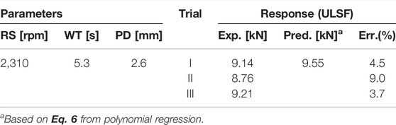
TABLE 5. Validation experiments for predicted maximum response.
3.4 Microstructural Analysis
The microstructure of the optimum condition (Trial I) is depicted in Figure 6 in bright field (a) and in polarized light (b, c, d, e, and f). It is clearly visible in Figure 5A the distinct zones resulting from the friction-based process: heat affected zone (HAZ), thermomechanical affected zone (TMAZ), and the stir zone (SZ); BM is the unaffected base material. For a deeper analysis, Figure 6B reveals how the grains are oriented and distributed in and nearby the processing zone. Figure 6C reveals details of the HAZ. Since this zone does not suffer plastic deformation but thermal cycling during the joining process, the grains are elongated on the rolling direction whit sizes corresponding to the BM. Differently from the aforementioned, TMAZ grains (Figure 6D) are moderately deformed/heated, being characterized by a deformed microstructure; these grains follow the direction of the retracting plunge, bending upwards. In reason of insufficient deformation/heat regime, these grains do not recrystallize. The SZ presents a different feature in reason of the high values of deformation/heat achieved during the joining, and therefore a fully recrystallized microstructure with fine equiaxial grains (typically found in RFSSW of aluminium alloys is noticeable (Reimann et al., 2017).
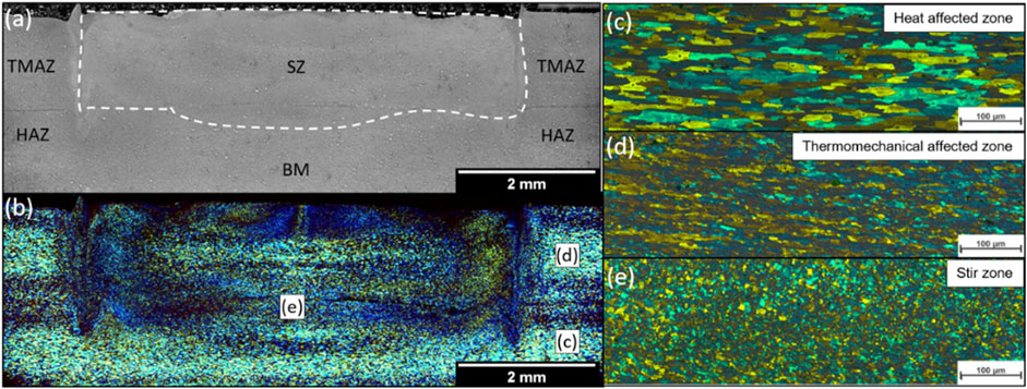
FIGURE 6. Light optical microscopy image of the Trial I joint in (A) bright field, (B) polarized light after the electrolytic etching, (C) heat affected zone, (D) thermomechanical affected zone, and (E) stir zone. The last three are indicated in (B). SZ stands for stir zone, TMAZ thermomechanical affected zone, HAZ heat affected zone and BM base material. The white dashed line delimits the processing zone.
Overall, the microstructure behavior is the expected one from friction-based processes, and a defect-free RFSSW joint is visible since neither pores and cracks nor grooves or cavities are identified and all produced and tested spot welds. It leads to conclude that the optimized parameters employed in this investigation act to perform a joint in an expected range of reliability, leading to a predictable microstructural and mechanical behavior expected for defect-free RFSS-welds.
4 Conclusion
The process parameters of Refill Friction Stir Spot Welding, i.e. Rotational Speed (RS), Welding Time (WT) and Plunge Depth (PD), were studied and optimized using a Machine Learning (ML) algorithm, namely Multivariate Polynomial Regression (MPR), from which the following conclusions can be drawn:
• Statistical metric coefficient of determination
• The model exhibited significant dependence on the quadratic features of the studied parameters, whereby WT2 and RS2 have a detrimental effect over the ULSF. Thus, this negative clout follows a down-concave parabolic behaviour from which low and high values of WT and RS lead to worse outcomes.
• An optimum parameter combination was obtained within the investigated parameter window (RS = 2,310 rpm, WT = 5.3 s and PD = 2.6 mm). Despite the satisfactory match between experimental and predicted results, the predicted optimum point did not correspond to the maximum obtainable ULSF. The disparity is related to oversimplification of certain training points by the model, as well as the slight difference in chemical composition between Alclad AA2024-T3 used in and AA2024-T3 used in this work.
• The microstructure exhibited clearly the distinct zones found in stir based-processes besides a defect-free joint. It highlights the reliability of the parameters employed for this investigation.
Although very promising results were obtained from the MPR model, no solid conclusions can be inferred on the adequacy of the model beyond the parameter window investigated. Moreover, as a future contribution, other ML algorithms, such as Gaussian Process Regression, Decision Tree Regression or Support Vector Regression should be considered and compared to the present solution.
Data Availability Statement
The raw data supporting the conclusion of this article will be made available by the authors, without undue reservation.
Author Contributions
PSE and WSC are the principal researchers, having developed the ML model and corresponding experimental validation. RPMG was responsible for the microstructural characterization and interpretation. STA-F is the scientific supervisor for this research and thus corrected the scientific output of the present article.
Conflict of Interest
The authors declare that the research was conducted in the absence of any commercial or financial relationships that could be construed as a potential conflict of interest.
Publisher’s Note
All claims expressed in this article are solely those of the authors and do not necessarily represent those of their affiliated organizations, or those of the publisher, the editors and the reviewers. Any product that may be evaluated in this article, or claim that may be made by its manufacturer, is not guaranteed or endorsed by the publisher.
Acknowledgments
The authors gratefully acknowledge financial support from the Austrian aviation program “Take Off” and from the Austrian Ministry for Climate Action, Environment, Energy, Mobility, Innovation and Technology BMK. The authors would like to acknowledge Magna for making available the joining equipment. Supported by TU Graz Open Access Publishing Fund.
References
Amancio Filho, S. T., and dos Santos, J. F. (2013). Method for Joining Metal and Plastic Workpieces. US20110131784A1.
Amancio-Filho, S. T., Bueno, C., dos Santos, J. F., Huber, N., and Hage, E. (2011b). On the Feasibility of Friction Spot Joining in Magnesium/Fiber-Reinforced Polymer Composite Hybrid Structures. Mater. Sci. Eng. A 528, 3841–3848. doi:10.1016/j.msea.2011.01.085
Amancio-Filho, S. T., Camillo, A. P. C., Bergmann, L., Santos, J. F. D., Kury, S. A. O. E., and Machado, N. G. A. (2011a). Preliminary Investigation of the Microstructure and Mechanical Behaviour of 2024 Aluminium Alloy Friction Spot Welds. Mater. Trans. 52, 985–991. doi:10.2320/matertrans.l-mz201126
Anderson, K., Weritz, J., and Kaufman, J. G. (2019). “Alclad 2024: High-Strength Aerospace Alloy,” in Properties and Selection of Aluminum Alloys (ASM International), 298–303. doi:10.31399/asm.hb.v02b.a0006598
André, N. M., Boualib, A., Maawad, E., Staron, P., Santos, J. F. D., Zheludkevich, M. L., et al. (2019). Corrosion Behavior of Metal – Composite Hybrid Joints: In Fl Uence of Precipitation State and Bonding Zones. Corros. Sci. 158, 108075. doi:10.1016/j.corsci.2019.07.002
André, N. M., Jorge, F., and Amancio-filho, S. T. (2020). Impact Resistance of Metal-Composite Hybrid Joints Produced by Frictional Heat. Compos. Struct. 233, 111754. doi:10.1016/j.compstruct.2019.111754
Bock, F. E., Paulsen, T., Brkovic, N., Rieckmann, L., Kroeger, D., et al. (2021). “Evaluation of Mechanical Property Predictions of Refill Friction Stir Spot Welding Joints via Machine Learning Regression Analyses on DoE Data,” in 24th International Conference on Material Forming (Liège, Belgique: ESAFORM 2021). doi:10.25518/esaform21.2589
Bouali, A. C., André, N. M., Silva Campos, M. R., Serdechnova, M., dos Santos, J. F., Amancio-Filho, S. T., et al. (2021). Influence of LDH Conversion Coatings on the Adhesion and Corrosion protection of Friction Spot-Joined AA2024-T3/CF-PPS. J. Mater. Sci. Technol. 67, 197–210. doi:10.1016/j.jmst.2020.06.038
Campanelli, L. C., Suhuddin, U. F. H., Santos, J. F. D., and Alcântara, N. G. D. (2012). Parameters Optimization for Friction Spot Welding of AZ31 Magnesium Alloy by Taguchi Method. Soldag. Insp. 17, 26–31. doi:10.1590/s0104-92242012000100005
Carvalho, W. S. D., Vioreanu, M. C., Lutz, M. R. A., Cipriano, G. P., and Amancio-filho, S. T. (2021). The Influence of Tool Wear on the Mechanical Performance of AA6061-T6 Refill Friction Stir Spot Welds. Materials (Basel) 14, 7252. doi:10.3390/ma14237252
Chen, Y., Chen, Y., Chen, J., Amirkhiz, B. S., Worswick, M. J., and Gerlich, A. P. (2015). Microstructures and Properties of Mg Alloy/DP600 Steel Dissimilar Refill Friction Stir Spot Welds Microstructures and Properties of Mg alloy/DP600 Steel Dissimilar Refill Friction Stir Spot Welds. Sci. Technol. Welding Joining 20, 494–501. doi:10.1179/1362171815Y.0000000033
Dong, H., Chen, S., Song, Y., Guo, X., Zhang, X., and Sun, Z. (2016). Refilled Friction Stir Spot Welding of Aluminum Alloy to Galvanized Steel Sheets. Mater. Des. 94, 457–466. doi:10.1016/j.matdes.2016.01.066
Effertz, P. S., Infante, V., Quintino, L., Suhuddin, U., Hanke, S., and dos Santos, J. F. (2016). Fatigue Life Assessment of Friction Spot Welded 7050-T76 Aluminium Alloy Using Weibull Distribution. Int. J. Fatigue 87, 381–390. doi:10.1016/j.ijfatigue.2016.02.030
Effertz, P. S., Quintino, L., and Infante, V. (2017). The Optimization of Process Parameters for Friction Spot Welded 7050-T76 Aluminium alloy Using a Taguchi Orthogonal Array. Int. J. Adv. Manuf. Technol. 91, 3683–3695. doi:10.1007/s00170-017-0048-0
Esteves, J. V., Goushegir, S. M., dos Santos, J. F., Canto, L. B., Hage, E., and Amancio-Filho, S. T. (2015). Friction Spot Joining of Aluminum AA6181-T4 and Carbon Fiber-Reinforced Poly(Phenylene Sulfide): Effects of Process Parameters on the Microstructure and Mechanical Strength. Mater. Des. 66, 437–445. doi:10.1016/j.matdes.2014.06.070
Gonçalves, J., dos Santos, J. F., Canto, L. B., and Filho, S. D. T. A. (2016). Improvement of Friction Spot Welding (FSpW) to Join Polyamide 6 and Polyamide 66/Carbon Fibre Laminate. Weld. Int. 30, 247–254. doi:10.1080/09507116.2015.1096466
Goushegir, S. M., Scharnagl, N., Dos Santos, J. F., and Amancio-filho, S. T. (2020). Durability of Metal-Composite Friction Spot Joints under Environmental Conditions. Materials (Basel) 13, 1–20. doi:10.3390/ma13051144
Goushegir, S. M., and Amancio-Filho, S. T. (2018). “Friction Spot Joining (FSpJ),” in Joining of Polymer‐Metal Hybrid Structures (John Wiley & Sons), 61–99. doi:10.1002/9781119429807.ch3
Hartl, R., Hansjakob, J., and Zaeh, M. F. (2020). Improving the Surface Quality of Friction Stir Welds Using Reinforcement Learning and Bayesian Optimization. Int. J. Adv. Manuf Technol. 110, 3145–3167. doi:10.1007/s00170-020-05696-x
Hastie, T., Friedman, J., and Tibshirani, R. (2001). “Model Assessment and Selection,” in The Elements of Statistical Learning: Data Mining, Inference, and Prediction (New York: Springer), 193–224. doi:10.1007/978-0-387-21606-5_7
Henrique, P., de Oliveira, F., de Traglia, S., Filho, A., and Santos, J. F. D. (2012). Estudo de Viabilidade da Soldagem de Termoplásticos por“Friction Spot Welding” (FSpW). Soldag. Insp. São Paulo 17, 96–103. doi:10.1590/S0104-92242012000200003
Junior, W. S., Emmler, T., Abetz, C., Handge, U. A., dos Santos, J. F., Amancio-Filho, S. T., et al. (2014). Friction Spot Welding of PMMA with PMMA/Silica and PMMA/Silica-g-PMMA Nanocomposites Functionalized via ATRP. Polymer 55, 5146–5159. doi:10.1016/j.polymer.2014.08.022
Kluz, R., Kubit, A., Trzepiecinski, T., and Faes, K. (2019). Polyoptimisation of the Refill Friction Stir Spot Welding Parameters Applied in Joining 7075-T6 Alclad Aluminium Alloy Sheets Used in Aircraft Components. Int. J. Adv. Manuf Technol. 103, 3443–3457. doi:10.1007/s00170-019-03711-4
Manente, N., Santos, J. F., and Amancio-filho, S. T. (2019). Evaluation of Joint Formation and Mechanical Performance of the AA7075-T6/CFRP Spot Joints Produced by Frictional Heat. Materials 12 (6), 891. doi:10.3390/ma12060891
Reimann, M., Goebel, J., and dos Santos, J. F. (2017). Microstructure and Mechanical Properties of Keyhole Repair Welds in AA 7075-T651 Using Refill Friction Stir Spot Welding. Mater. Des. 132, 283–294. doi:10.1016/j.matdes.2017.07.013
Rosendo, T., Parra, B., Tier, M. A. D., da Silva, A. A. M., dos Santos, J. F., Strohaecker, T. R., et al. (2011). Mechanical and Microstructural Investigation of Friction Spot Welded AA6181-T4 Aluminium Alloy. Mater. Des. 32, 1094–1100. doi:10.1016/j.matdes.2010.11.017
Schilling, C., and dos Santos, J. F. (2004). Method and Device for Joining at Least Two Adjoining Work Pieces by Friction Welding. US6722556B2.
Shen, Z., Chen, Y., Hou, J. S. C., Yang, X., and Gerlich, A. P. (2015). Influence of Processing Parameters on Microstructure and Mechanical Performance of Refill Friction Stir Spot Welded 7075-T6 Aluminium Alloy Influence of Processing Parameters on Microstructure and Mechanical Performance of Refill Friction Stir Spot Welded 7075-T6 Aluminium Alloy. Sci. Technol. Welding Joining 20, 48–57. doi:10.1179/1362171814Y.0000000253
Shen, Z., Ding, Y., Chen, J., and Gerlich, A. P. (2016). Comparison of Fatigue Behavior in Mg/Mg Similar and Mg/Steel Dissimilar Refill Friction Stir Spot Welds. Int. J. Fatigue 92, 78–86. doi:10.1016/j.ijfatigue.2016.06.033
Shen, Z., Yang, X., Yang, S., Zhang, Z., and Yin, Y. (2014). Microstructure and Mechanical Properties of Friction Spot Welded 6061-T4 Aluminum Alloy. Mater. Des. 54, 766–778. doi:10.1016/j.matdes.2013.08.021
Shen, Z., Yang, X., Zhang, Z., Cui, L., and Li, T. (2013). Microstructure and Failure Mechanisms of Refill Friction Stir Spot Welded 7075-T6 Aluminum Alloy Joints. J. Mater. 44, 476–486. doi:10.1016/j.matdes.2012.08.026
Suhuddin, U., Fischer, V., Kroeff, F., and dos Santos, J. F. (2014). Microstructure and Mechanical Properties of Friction Spot Welds of Dissimilar AA5754 Al and AZ31 Mg Alloys. Mater. Sci. Eng. A 590, 384–389. doi:10.1016/j.msea.2013.10.057
Tier, M., Rosendo, T. S., dos Santos, J. F., and Mazzaferro, J. A. E. (2009). “A Study about the Mechanical Properties of Alclad AA2024 Connections Processed by Friction Spot Welding 1,” in 64° Congr. Int. da Assoc. Brasileira de Metalurgia ABM, Belo Horizonte - MG, 13 a 17 de Julho de 2009.
Keywords: refill friction stir spot welding, optimization, machine learning, polynomial regression, AA2024-T3
Citation: Effertz PS, de Carvalho WS, Guimarães RPM, Saria G and Amancio-Filho ST (2022) Optimization of Refill Friction Stir Spot Welded AA2024-T3 Using Machine Learning. Front. Mater. 9:864187. doi: 10.3389/fmats.2022.864187
Received: 28 January 2022; Accepted: 28 February 2022;
Published: 08 April 2022.
Edited by:
Hui Huang, Oak Ridge National Laboratory (DOE), United StatesReviewed by:
Wei Zhang, Oak Ridge National Laboratory (DOE), United StatesAkshansh Mishra, Stir Research Technologies, India
Copyright © 2022 Effertz, de Carvalho, Guimarães, Saria and Amancio-Filho. This is an open-access article distributed under the terms of the Creative Commons Attribution License (CC BY). The use, distribution or reproduction in other forums is permitted, provided the original author(s) and the copyright owner(s) are credited and that the original publication in this journal is cited, in accordance with accepted academic practice. No use, distribution or reproduction is permitted which does not comply with these terms.
*Correspondence: P. S. Effertz, cGVkcm8uZWZmZXJ0ekB0dWdyYXouYXQ=; S. T. Amancio-Filho, c2VyZ2lvLmFtYW5jaW9AdHVncmF6LmF0