 Xiaoming Cao
 Lei Wang
 Zhao Li
95% of researchers rate our articles as excellent or good
Learn more about the work of our research integrity team to safeguard the quality of each article we publish.
Find out more
ORIGINAL RESEARCH article
Front. Mater. , 28 November 2022
Sec. Mechanics of Materials
Volume 9 - 2022 | https://doi.org/10.3389/fmats.2022.1064695
This article is part of the Research Topic Design and Mechanical Failure of Deep-Sea Pressure Structures View all 6 articles
In this paper, an analytical approach for global buckling of ring-stiffened sandwich cylindrical shells is presented with layerwise theory (LWT). Appropriate displacement functions are assumed according to the boundary conditions and the deformation characteristics of the inner and outer shells. The strain energies of the inner and outer shells and the ribs and the work done by external forces are derived with the help of classical laminate theory. Furthermore, the Rayleigh–Ritz method is employed to obtain the critical buckling load of ring-stiffened sandwich cylindrical shells. The ribband width has a great influence on the precision of calculation of the critical buckling load, and a formula for calculating this width is obtained by data fitting. To confirm the accuracy of the proposed formulation, a numerical simulation is carried out by using Abaqus FEM software. The results show that the proposed approach has high accuracy in predicting the global buckling behavior of ring-stiffened sandwich cylindrical shells. Finally, the effects on the buckling performance of ring-stiffened sandwich cylindrical shells caused by changing the inner and outer shell thicknesses and the rib height, thickness, and spacing are explored.
Sandwich cylindrical shells are generally composed of two shells of the same material between which is sandwiched a core of a different material, which may be a lightweight filler core, a lattice core, or a skeleton cores (Mahamood et al., 2012; Chen et al., 2015). With their advantages of high strength and stability, strong impact resistance, and low density, sandwich cylindrical shells are widely used in various engineering structures (Lopatin et al., 2012; Gholami Ansari et al., 2015; Shahgholian-Ghahfarokhi et al., 2019).
Among the class of skeleton-reinforced sandwich cylindrical shells are ring-stiffened shells, in which ring ribs are sandwiched between the inner and outer shells to provide resistance to external loads. Strength failure and buckling are the main failure modes of ring-stiffened sandwich cylindrical shells when these are subjected to both axial and radial loads, and buckling includes local buckling, rib crippling, and global buckling. Unfortunately, to date, there have been no reports of systematic research on the strength and stability of ring-stiffened sandwich cylindrical shells.
Sandwich cylindrical shells were developed from single-layer cylindrical shells. Flugge (1973) and Timoshenko and Gere (1963), among others, have established a method for the analysis of buckling of unstiffened single-layer cylindrical shells. Xie et al. (2003), among others, have systematically studied the strength and stability of stiffened single-layer cylindrical shells. The total potential energy of the structure was calculated using classical laminate theory (CLT), and a formula for the critical global buckling load of stiffened single-layer cylindrical shells was derived using the Rayleigh–Ritz method. Tian et al. (1999) and Ghorbanpour Arani et al. (2010) performed the elastic buckling analysis of ring-stiffened cylindrical shells under general pressure loading via the Ritz method. Carveli et al. (2001), Messager et al. (2002), and Ren et al. (2014) obtained a formula for the critical buckling load of composite stiffened cylindrical shells by using the smeared stiffener method (SSM). After decades of development, the research on the strength and stability of single-layer cylindrical shells has become mature, and the semi-analytical and semi-empirical formulas can meet the precision requirements of engineering design. However, there are significant differences in form of structure, the works of single-layer cylindrical shells cannot be directly applied to the sandwich cylindrical shells.
Over the years, there have been many studies of sandwich cylindrical shells. The buckling of such shells with both ends clamped under external pressure was studied by Lopatin and Morozov (2015) using the Galerkin method. Jalali et al. (2011) used first-order shear deformation theory (FOSDT) to analyze the buckling of sandwich cylindrical shells with variable shell thickness. Alibeigloo and Rajaee Piteh Noee (2017) studied the statics and free vibration of sandwich cylindrical shells consisting of a layer of functionally graded material sandwiched between ceramic and metal. Chen et al. (2015) carried out both experimental and theoretical investigations of the influence of defects on the bending and shearing mechanical properties of sandwich cylindrical shells strengthened by carbon fiber conical trusses. Han et al. (2004) explored the buckling of foam core sandwich cylindrical shells with large slenderness ratio under external pressure. Estrada et al. (2012) investigated the buckling behavior of sandwich cylindrical shells buried in soil. Sofiyev et al. (2015) used FOSDT to analyze the vibration of sandwich cylindrical shells on elastic foundations. Garg et al. (2021) carried out a detailed study in which they analyzed various theories of statics, buckling, and vibration of sandwich structures based on an extensive survey of the literature, and they presented a summary of the status of research on sandwich structures. Many studies have shown that the most important failure mode of sandwich cylindrical shells is global buckling (Wodesenbet et al., 2003; Bisagni et al., 2006; Frulloni et al., 2007; Morozov et al., 2011; Zheng et al., 2015).
Many scholars have done a lot of work on the global buckling of sandwich cylindrical shells. Ghahfarokhi and Rahimi (2018) established a theoretical approach for analyzing the global buckling of sandwich cylindrical shells with lattice cores. A force and moment effect analysis was used to evaluate the influence of the lattice cores on the global equivalent stiffness, and finally the critical buckling load was obtained by the Rayleigh–Ritz method. Shahgholian et al. (2020) used FOSDT to calculate the global stiffness matrix of sandwich cylindrical shells. A formula for the critical buckling load was obtained by the Rayleigh–Ritz method. To verify the accuracy of this approach, the results obtained have been compared with those of other methods described in the literature, including the finite element method (FEM). Huang et al. (2017) assumed that the elastoplastic behavior of the shell material changed smoothly according to a power law and thereby established a semi-analytical method for describing the elastoplastic buckling of sandwich cylindrical shells under the combined action of axial and torsional loads. Although much research has been done on the global buckling of sandwich cylindrical shells, this has mostly been done using equivalent-single layer (ESL) theory. In this approach, a sandwich cylindrical shell is taken as being equivalent to a single-layer cylindrical shell, the global stiffness matrix of the sandwich cylindrical shell is then calculated on this basis, and the energy method is then used to obtain a formula for the critical buckling load. However, this method has some serious shortcomings, for example, the global stiffness matrix is too complex to calculate and the mechanism of buckling associated with each part of the structure is unclear. For this reason, it is urgent to develop an analysis approach with clear mechanical mechanism, small amount of calculation and high accuracy.
In this paper, the global buckling of ring-stiffened sandwich cylindrical shells is studied theoretically. First, a reasonable virtual displacement is assumed according to the boundary conditions and the deformation characteristics of the shells during global buckling. To obtain the total potential energy of the structure, the strain energies of the inner and outer shells and the ribs of the sandwich structure are calculated, and a formula for the critical global buckling load is then derived using the Rayleigh–Ritz method. Second, the width of the ribband, which is an important parameter representing the coupling effect of the inner and outer shells and the ribs, is analyzed, and a formula for calculating this is established. Third, Abaqus FEM software is employed to analyze the global buckling of the sandwich cylindrical shell, and the results are then compared with those of the proposed analytical approach to verify the accuracy of the latter. Finally, the influences of the inner shell thickness, outer shell thickness, rib height, rib thickness, and rib spacing on global stability are investigated. The illustration of the organization of this article is shown in Figure 1.
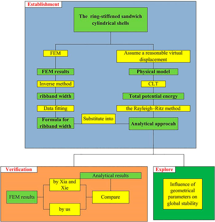
Figure 1. The illustration of the organization of this article.
The approach to analyzing the global buckling of ring-stiffened sandwich cylindrical shells presented in this paper avoids the need to calculate a complex global stiffness matrix. As well as requiring fewer calculations, it has a clear physical meaning and enables a quantitative description to be given of the contributions of the inner and outer shells and the ribs to global stability. On the one hand, the results obtained here provide a deeper understanding of the mechanisms involved during buckling of skeleton-reinforced sandwich cylindrical shells and thereby theoretical guidance for the preliminary design of ring-stiffened sandwich cylindrical shells. On the other hand, these results can also be used as a basis for rapid optimization of structural designs of such shells.
Energy theory is a general approach to buckling analysis, in this section, the physical model of ring-stiffened sandwich cylindrical shells subjected to external hydrostatic pressure is introduced at first, and then the total potential energy is obtained by the classical laminated theory, finally, the critical global buckling load of ring-stiffened sandwich cylindrical shells is derived with the help of the Rayleigh–Ritz method.
The schematic representation of the ring-stiffened sandwich cylindrical shells was shown in Figure 2, which have two shells, namely, the inner and outer shells. The two shells are tied together by ring ribs. The ring ribs are the rings produced by the inner and outer shell cut out a plane perpendicular to the x axis, and the geometric parameters are as follows: L is the total length of the shells, R0 and R1 are the radii of the middle surfaces of the inner and outer shells, respectively. L is the rib spacing, x and φ are axial and circumferential coordinates, and h is the rib height.

Figure 2. Schematic of ring-stiffened sandwich cylindrical shells.
In this subsection, the potential energy of the sandwich cylindrical shells is calculated using CLT, which assumes a reasonable virtual displacement based on the boundary conditions and the deformation characteristics during global buckling.
As shown in Figure 3, when global buckling of the sandwich cylindrical shells occurs, the deformation modes of the inner and outer shells are both sinusoidal and the amplitudes of deformation are roughly equal, and so it can be assumed that the inner and outer shells have the same virtual displacement during global buckling. In addition, for shells with both ends simply supported, the circumferential and radial displacements should be zero at the ends. Taking the left end as the coordinate origin, the virtual displacements satisfying the displacement boundary condition can be assumed to have the following forms:
where u, v, and w are the axial, circumferential, and radial displacements, m and n are the wavenumbers of the axial half-wave and circumferential whole wave when global buckling occurs, and A, B, and C are constants representing the amplitudes of displacements.
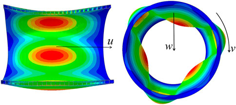
Figure 3. Deformation diagram of shells during buckling mode.
The strain energies of the outer and inner shells and the ribs, together with the external force work, will now each be calculated. The detailed calculations can be found in the work of Xie et al. (2003).
Similar to the study of plate bending, the strain of middle surfaces of shell can also be characterized by the following six components: two tensile and compressive strains
Then we can obtain the strain at any point of section of shell:
Where
According to the definition of strain energy, the strain energy of any elastic body can be derived as:
For the straight normal assumption,
Under biaxial stress state,
Take Eq. 4 into Eq. 3, and the research object is cylindrical, so dy,
where ν is the Poisson’s ratio of material, t1 is the thickness of the outer shell,
Similarly, the strain energy of the inner shell also comprises two parts, namely, the bending strain energy
where t2 is the thickness of the inner shell,
The strain energy of the ribs comprises the bending strain energy and compressing strain energy, but the latter will be ignored because it is very small compared with the former. To compensate for this simplification, the thicknesses of the inner and outer shells should be added to the thickness of the ribs, spread evenly on them, when calculating the tension strain energy. The strain energy of the ribs is given by
where R is the radius at the neutral axis and I is the moment of inertia of the rib section with ribband. I can be calculated as follows:
where
To analyze the external force work produced when the shell deviates from its initial position, two rectangular elements are cut out from the inner shell and shells, with two cross sections and two longitudinal sections. The element on the outer shell is subjected to three external forces: a longitudinal force
The expression for the external force work done by the longitudinal force is
While that for the external force work done by the circumferential force and the external pressure is
For ring-stiffened sandwich cylindrical shells sealed with hemispherical heads at both ends,
where k20 and k21 are the circumferential force coefficients of the inner and outer shells, respectively, and are given by
The total potential energy Π, which is the sum of the strain energy and the external force work is given by
To simplify this formula, terms on the right-hand side that are small compared with the others are to be omitted. Since t1/R1 for the thin-shell structure is about
Similarly,
In the expressions for U11 and U10, the terms
In this subsection, the global stability equation of the structure is established using the Rayleigh–Ritz method and is then solved to calculate the critical global buckling load of ring-stiffened sandwich cylindrical shells.
The total potential energy Π is substituted into the basic relations of the Rayleigh–Ritz method,
namely,
where
The following homogeneous linear equations are thereby obtained:
As is well known, only when the determinant constructed from the coefficients of (21) is equal to zero will the equations have nonzero solutions, and thus
After expansion of the determinant, the global stability equation of the ring-stiffened sandwich cylindrical shells is obtained as follows:
Solution of the global stability equation gives the following formula for the critical global buckling load:
where m and n are the values that minimize the critical global buckling load, and
Here,
It can be seen from the above determination of the critical global buckling load that the ribband width in Eq. 7 is the only parameter for which a calculation method has not been given. When a rib bends, part of the shell connected with it also deforms, and these parts of the shell is called the ribband. Therefore, when calculating the cross-sectional moment of inertia of the ribs, ribband should be included. Strictly speaking, only part of the shell in each rib space is deformed together with the ribs, and so the ribband width b can be written as
where l is the rib spacing and
There have been no reports in the literature of analytical methods to determine the ribband width, and it is generally calculated using empirical formulas for different structural forms. It can be seen from the results of calculations of the critical global buckling load of stiffened single-layer cylindrical shells that the ribband width has little influence on the precision of such calculations. Therefore, for convenience of calculation, the ribband width is usually taken as the whole rib spacing. However, the ribband width does have a great influence on the accuracy of calculations of critical global buckling loads of sandwich cylindrical shells, and it has been suggested by Xia and Xie (2004) that it should be taken to be 0.6 times the rib spacing. Unfortunately, we have performed a large number of calculations showing that the ribband width is not always either the whole rib spacing or 0.6 times this spacing, but is a variable parameter. Therefore, a formula needs to be derived for calculating the width of the ribband of sandwich cylindrical shells.
In this section, Abaqus FEM software is first used to analyze the critical global buckling load of sandwich cylindrical shells. This FEM result is then used in the analytical approach to determine the ribband width. Second, the influence of geometrical parameters on the ribband width is explored, and the parameters with little influence are omitted. The relationships between the ribband width and the other parameters is then determined in a step-by-step manner. Finally, a formula for the ribband width of ring-stiffened sandwich cylindrical shells is obtained.
The parameters of the FEM model (Model 1) was shown in Table 1, and the global buckling mode and critical global buckling load Pcr of sandwich cylindrical shells calculated by Abaqus was shown in Figure 4. The finite element type of shells and ribs are S4R, and the inner shell and the outer shell and the ribs are connected by “Tie”, the size of each finite element is about h/3, the displacement boundary condition is simply support at both ends, the part type is shell, and the material is Titanium Alloy. The sandwich cylindrical shells are subjected to a radial uniform external pressure P and axial load P2 at the same time, with P2 acting on the outer surfaces of the ribs at the ends. P2 is given by

TABLE 1. Model 1 parameter setting.
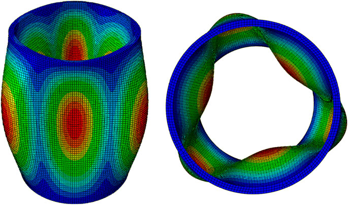
Figure 4. Finite element calculation of global buckling mode.
Pcr is calculated by the FEM to be 56.029 MPa, which is brought into the proposed analytical method for buckling analysis of the ring-stiffened sandwich cylindrical shells, then, the width of the ribband can be determined to be b = 2.381 cm. According to both the FEM and the analytical method, the buckling mode has whole ring wavenumber n = 3 and longitudinal half-wave wavenumber m = 1.
We now derive a formula for calculating the ribband width. To avoid any influence of the global size of the cylindrical shells on the calculation, all the geometrical parameters (
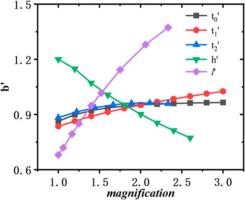
Figure 5. Variation dimensionless ribband width with parameter magnification.
As can be seen from Figure 5, change of
As can be seen from Figure 6, the curves of Models 1 s, 2 s, and 3 s are close, but differ significantly from that of Model 4 s, which proves again that changes in
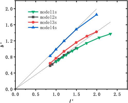
Figure 6. Curves of
From the above observations and analysis, it can be seen that the problem of determining the ribband width is equivalent to that of determining
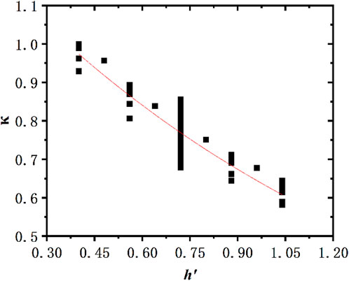
Figure 7. Fitting result for
Putting this fitting result into
Finally, to obtain the formula for calculating the ribband width, both sides of this equation are multiplied by the feature dimension R/10 to restore the dimensional quantities:
Abaqus 6.12 FEM software is used for numerical simulation, and the FEM results are compared with those of the analytical method proposed in this paper to verify the accuracy of the latter. In contrast to the parameter changes used in the determination of the formula for the ribband width, the models used in this section not only have a wider range of geometrical parameters, but also involve changes in the slenderness ratio or the global size. The finite element type is S4R, the size of each finite element is about h/3, the displacement boundary condition is simply support at both ends, and the material is Titanium Alloy. Table 2 shows the dimensions of the models and a comparison between the FEM results and analytical results for each model, and Figure 8 shows the buckling mode of Model f. It can be seen from Table 2 that the error in Pcr using the analytical approach and the FEM is less than 10% for all models, and the wavenumbers of the axial half-wave and the circumferential whole wave are consistent during buckling. Therefore, the analytical approach to global buckling of sandwich cylindrical shells proposed in this paper appears to have good accuracy and applicability.
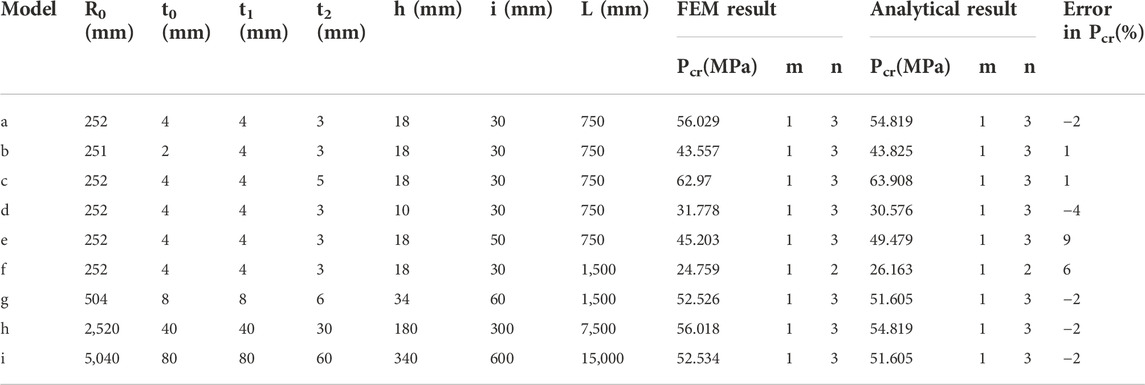
TABLE 2. Dimensions of models and comparison between FEM and analytical results.
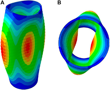
Figure 8. Buckling mode of model f: (A) (Front view) and (B) (Bottom view).
To verify whether the proposed approach is suitable for buckling analysis of sandwich cylindrical shells made of other metallic materials, a buckling analysis of sandwich cylindrical shells made of steel (E = 210000MPa, ν = 0.3) is carried out. Table 3 shows the dimensions and a comparison between FEM and analytical results, it can be seen that the method of buckling analysis proposed in this paper is also suitable for steel ring-stiffened sandwich cylindrical shells.
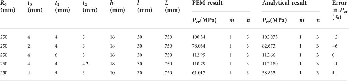
TABLE 3. Comparison of buckling analysis results for steel models.
The buckling analysis of six dimensions of steel (E = 196000MPa, ν = 0.3) ring-stiffened sandwich cylindrical shells were performed by Xia and Xie with FEM, which are shown in Table 4. As we can see from Table 4, the results of the analytical approach proposed in this paper are in good agreement with the results of FEM by them.
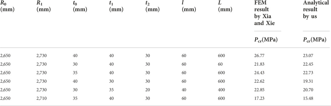
TABLE 4. Comparison of buckling analysis results for steel models.
The influences of the geometrical parameters on the critical global buckling load of sandwich cylindrical shells are explored with the help of the approach to buckling analysis proposed in this paper. We keep the radius of the inner surface of the inner shell and the total length of the shell constant and change the other geometrical parameters of Model 1. As shown in Figure 9, the critical global buckling load increases with increasing inner shell thickness, outer shell thickness, rib height, and rib thickness, but decreases with increasing rib spacing. When all the geometrical parameters are changed by the same multiple, it is the change in rib height that has the greatest influence on the critical global buckling load. Increasing the rib height can significantly increase the critical load, whereas the inner shell thickness, outer shell thickness, rib thickness, and rib spacing have relatively little influence on it.
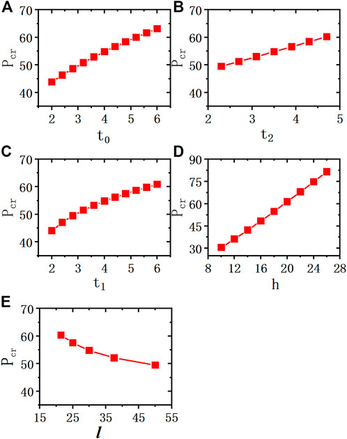
Figure 9. Influence of geometrical parameters on critical global buckling load: (A) (Pcr with t0), (B) (Pcr with t2), (C) (Pcr with t1), (D) (Pcr with h), (E) (Pcr with l).
It can be seen that the contributions of the inner shell, outer shell, and ribs to global stability can be determined by calculating the terms in Eq. 23. Taking Model 1 as an example, the contributions of each term to global stability are shown in Figure 10. It can be seen that for this model, the contribution of ribs with ribband to global stability is 83%, while the contribution of the inner and outer shells is less than 10%. In other words, the ribs play a decisive role in the global stability of ring-stiffened sandwich cylindrical shells. Furthermore, the bending stiffness of the ribs is determined by EI, and EI ∝ h3, and so the rib height has the greatest influence on the critical global buckling load, which means that the stability of sandwich cylindrical shells can be improved by appropriately increasing the rib height.
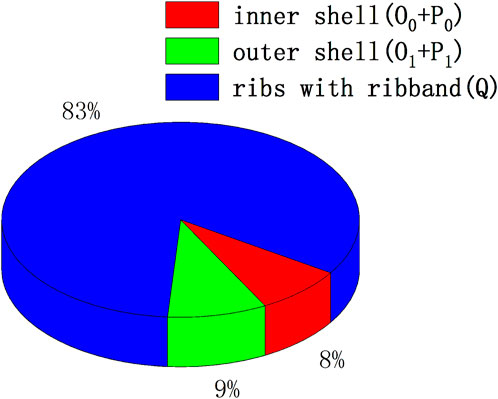
Figure 10. Contributions of the inner shell, outer shell, and ribs with ribband to global stability.
In this paper, to analyze the global buckling of ring-stiffened sandwich cylindrical shells, first, a reasonable virtual displacement was assumed according to the boundary conditions and the deformation characteristics of the inner and outer shells during global buckling. Second, the total potential energy was obtained using classical laminate theory, and a formula for the critical global buckling load was then derived using the Rayleigh–Ritz method. All the terms in this formula have clear physical meanings, which intuitively show the contribution of the inner shell, the outer shell, and the ribs to global stability. Finally, a numerical simulation of the global buckling of ring-stiffened sandwich cylindrical shells was carried out using Abaqus FEM software. The FEM results are in good agreement with those of the proposed analytical approach, which proves that this approach has good accuracy and applicability. The main conclusions are as follows:
1. The ribband width is an important parameter characterizing the coupling effect of the inner shell, outer shell, and ribs, and it has a significant influence on the precision of calculations of the critical global buckling load. This paper explored and evaluated the influence of different geometrical parameters on ribband width, by omitting those with little influence and fitting an expression for the ribband width in terms of the others. A formula for calculating the ribband width was determined in a step-by-step manner.
2. The influence of geometrical parameters on the global buckling of sandwich cylindrical shells was investigated using the proposed analytical approach. The critical global buckling load increases with increasing inner shell thickness, outer shell thickness, rib height, and rib thickness, but decreases with increasing rib spacing. Furthermore, changes in the rib height have the greatest influence on the critical global buckling load, while the thicknesses of the inner and outer shells and the ribs and the rib spacing have relatively little influence. The contribution of the ribs to global stability is more than 80%, while those of the inner and outer shells are less than 10%, i.e., the ribs play a decisive role in the global stability of ring-stiffened sandwich cylindrical shells.
3. Although a lot of work has been done on the analytical approach to global buckling of ring-stiffened sandwich cylindrical shells in this paper, there are still some deficiencies that need to be further studied: the analytical method for ribband width have not been obtained, and on experimental results can be used for verification.
4. Next the formula of ribband width will be established by an analytical approach, and, if conditions permit, we will conduct an experimental study on global buckling of ring-stiffened sandwich cylindrical shells.
The original contributions presented in the study are included in the article/supplementary material, further inquiries can be directed to the corresponding author.
XC was in charge of conceptualization, methodology and Writing-Original Draft of this article, LW was in charge of supervision and formal analysis, ZL contributed to the validation, writing-review and editing, HZ and XW was responsible for the investigation. All authors contributed critically to the drafts and gave final approval for publication.
This work was supported by the Young Top-Notch Talent Cultivation Program of Hubei Province.
The authors declare that the research was conducted in the absence of any commercial or financial relationships that could be construed as a potential conflict of interest.
All claims expressed in this article are solely those of the authors and do not necessarily represent those of their affiliated organizations, or those of the publisher, the editors and the reviewers. Any product that may be evaluated in this article, or claim that may be made by its manufacturer, is not guaranteed or endorsed by the publisher.
Alibeigloo, A., and Rajaee Piteh Noee, A. (2017). Static and free vibration analysis of sandwich cylindrical shell based on theory of elasticity and using DQM. Acta Mech. 228 (12), 4123–4140. doi:10.1007/s00707-017-1914-4
Bisagni, C., and Cordisco, P. (2006). Post-buckling and collapse experiments of stiffened composite cylindrical shells subjected to axial loading and torque. Compos. Struct. 73 (2), 138–149. doi:10.1016/j.compstruct.2005.11.055
Carvelli, V., Panzeri, N., and Poggi, C. (2001). Buckling strength of GFRP under-water vehicles. Compos. Part B Eng. 32 (2), 89–101. doi:10.1016/s1359-8368(00)00063-9
Chen, M., Zhu, X., Lei, H., Chen, H., and Fang, D. (2015). Effect of defect on the compressive response of sandwich structures with carbon fiber pyramidal truss cores. Int. J. Appl. Mech. 07 (01), 1550004. doi:10.1142/s1758825115400049
Estrada, C., Godoy, L., and Flores, F. (2012). Buckling of vertical sandwich cylinders embedded in soil. Thin-Walled Struct. 61, 188–195. doi:10.1016/j.tws.2012.05.010
Frulloni, E., Kenny, J., Conti, P., and Torre, L. (2007). Experimental study and finite element analysis of the elastic instability of composite lattice structures for aeronautic applications. Compos. Struct. 78 (4), 519–528. doi:10.1016/j.compstruct.2005.11.013
Garg, A., Belarbi, M., Chalak, H., and Chakrabarti, A. (2021). A review of the analysis of sandwich FGM structures. Compos. Struct. 258, 113427. doi:10.1016/j.compstruct.2020.113427
Ghahfarokhi, D., and Rahimi, G. (2018). An analytical approach for global buckling of composite sandwich cylindrical shells with lattice cores. Int. J. Solids Struct. 146, 69–79. doi:10.1016/j.ijsolstr.2018.03.021
Gholami, R., Ansari, R., Darvizeh, A., and Sahmani, S. (2015). Axial buckling and dynamic stability of functionally graded microshells based on the modified couple stress theory. Int. J. Str. Stab. Dyn. 15 (04), 1450070. doi:10.1142/s0219455414500709
Ghorbanpour Arani, A., Loghman, A., Mosallaie Barzoki, R., and Kolahchi, R. (2010). Elastic buckling analysis of ring and stringer-stiffened cylindrical shells under general pressure and axial compression via the Ritz method. J. Solid Mech. 2 (4), 332–347.
Han, J., Kardomateas, G., and Simitses, G. (2004). Elasticity, shell theory and finite element results for the buckling of long sandwich cylindrical shells under external pressure. Compos. Part B Eng. 35 (6-8), 591–598. doi:10.1016/j.compositesb.2003.07.002
Huang, H., Zhang, Y., and Han, Q. (2017). Inelastic buckling of FGM cylindrical shells subjected to combined axial and torsional loads. Int. J. Str. Stab. Dyn. 17 (09), 1771010. doi:10.1142/s0219455417710109
Jalali, s., Naei, m., and Poorsolhjouy, a. (2011). Buckling of circular sandwich plates of variable core thickness and fgm face sheets. Int. J. Str. Stab. Dyn. 11 (02), 273–295. doi:10.1142/s0219455411004099
Lopatin, A., and Morozov, E. (2012). Buckling of a composite cantilever circular cylindrical shell subjected to uniform external lateral pressure. Compos. Struct. 94 (2), 553–562. doi:10.1016/j.compstruct.2011.08.021
Lopatin, A., and Morozov, E. (2015). Buckling of the composite sandwich cylindrical shell with clamped ends under uniform external pressure. Compos. Struct. 122, 209–216. doi:10.1016/j.compstruct.2014.11.048
Mahamood, R. M., Akinlabi, E. T., Shukla, M., and Pityana, S. L. (2012). Functionally graded material: An overview. World Congr. Eng. 3, 2–6.
Messager, T., Pyrz, M., Gineste, B., and Chauchot, P. (2002). Optimal laminations of thin underwater composite cylindrical vessels. Compos. Struct. 58 (4), 529–537. doi:10.1016/s0263-8223(02)00162-9
Morozov, E., Lopatin, A., and Nesterov, V. (2011). Buckling analysis and design of anisogrid composite lattice conical shells. Compos. Struct. 93 (12), 3150–3162. doi:10.1016/j.compstruct.2011.06.015
Ren, M., Li, T., Huang, Q., and Wang, B. (2014). Numerical investigation into the buckling behavior of advanced grid stiffened composite cylindrical shell. J. Reinf. Plastics Compos. 33 (16), 1508–1519. doi:10.1177/0731684414537881
Shahgholian, D., Safarpour, M., Rahimi, A., and Alibeigloo, A. (2020). Buckling analyses of functionally graded graphene-reinforced porous cylindrical shell using the Rayleigh–Ritz method. Acta Mech. 231 (5), 1887–1902. doi:10.1007/s00707-020-02616-8
Shahgholian-Ghahfarokhi, D., and Rahimi, G. (2019). Buckling analysis of composite lattice sandwich shells under uniaxial compression based on the effective analytical equivalent approach. Compos. Part B Eng. 174, 106932. doi:10.1016/j.compositesb.2019.106932
Sofiyev, A., Hui, D., Valiyev, A., Kadioglu, F., Turkaslan, S., Yuan, G., et al. (2015). Effects of shear stresses and rotary inertia on the stability and vibration of sandwich cylindrical shells with FGM core surrounded by elastic medium. Mech. Based Des. Struct. Mach. 44 (4), 384–404. doi:10.1080/15397734.2015.1083870
Tian, J., Wang, C. M., and Swaddiwudhipong, S. (1999). Elastic buckling analysis of ring-stiffened cylindrical shells under general pressure loading via the Ritz method. Thin-walled Struct. 35 (1), 1–24. doi:10.1016/s0263-8231(99)00012-9
Timoshenko, S. P., and Gere, J. M. (1963). Theory of elastic stability. 2nd ed. New York, USA: McGraw-Hill.
Wodesenbet, E., Kidane, S., and Pang, S. (2003). Optimization for buckling loads of grid stiffened composite panels. Compos. Struct. 60 (2), 159–169. doi:10.1016/s0263-8223(02)00315-x
Xia, X., and Xie, Z. (2004). Stress and stability analysis of double shell structure. J. east china Shipbuild. Inst. Nat. Sci. Ed. 18 (1), 10–12.
Xie, Z., Wang, Z., and Wu, J. (2003). Analysis of submarine structures (in Chinese). Wuhan, China: Huazhong University of Science and Technology Press, 74–82.
Keywords: deep-sea, pressure structure, global buckling, analytical approach, sandwich cylindrical shells, ring-stiffened
Citation: Cao X, Wang L, Li Z, Zhang H and Wang X (2022) An analytical approach to global buckling of ring-stiffened sandwich cylindrical shells. Front. Mater. 9:1064695. doi: 10.3389/fmats.2022.1064695
Received: 08 October 2022; Accepted: 14 November 2022;
Published: 28 November 2022.
Edited by:
Yu Zhang, China University of Petroleum, Beijing, ChinaReviewed by:
Yong Bai, Zhejiang University, ChinaCopyright © 2022 Cao, Wang, Li, Zhang and Wang. This is an open-access article distributed under the terms of the Creative Commons Attribution License (CC BY). The use, distribution or reproduction in other forums is permitted, provided the original author(s) and the copyright owner(s) are credited and that the original publication in this journal is cited, in accordance with accepted academic practice. No use, distribution or reproduction is permitted which does not comply with these terms.
*Correspondence: Zhao Li, bGl6aUB1c3RjLmVkdS5jbg==
Disclaimer: All claims expressed in this article are solely those of the authors and do not necessarily represent those of their affiliated organizations, or those of the publisher, the editors and the reviewers. Any product that may be evaluated in this article or claim that may be made by its manufacturer is not guaranteed or endorsed by the publisher.
Research integrity at Frontiers
Learn more about the work of our research integrity team to safeguard the quality of each article we publish.