 Tao Zhang
 Yuxin Zhang
 Hexin Zhang
94% of researchers rate our articles as excellent or good
Learn more about the work of our research integrity team to safeguard the quality of each article we publish.
Find out more
ORIGINAL RESEARCH article
Front. Mater., 21 October 2022
Sec. Smart Materials
Volume 9 - 2022 | https://doi.org/10.3389/fmats.2022.1055635
This article is part of the Research TopicAdvanced Materials and Techniques for Structural Monitoring, Analysis and ControlView all 16 articles
As light and efficient large-span space structures, beam string structures have been widely used since the 1980s. Within them, cables are the main force-bearing component; their level of tension determines the overall stiffness, performance and structural safety of the beam string structures. Real-time monitoring of the cable force during the construction and service periods is an important and effective measure to ensure the safety of the cable structure. At present, the vibration method is widely used in nearly all common engineering practices for cable force identification/monitoring because of its simplicity and efficiency. However, the vibration of the cable segment will be affected by the whole structure, so the cable force-frequency relationship based on the simple single cable model cannot meet the accuracy requirement of cable force identification of the beam string structure. Therefore, in this paper, through finite element simulation and theoretical analysis, a three-stage criterion is proposed to develop a new method for obtaining the local modal information of the tensioned cable segment where the influence of the overall structure is considered. The new method’s performance was compared with the results obtained by the vibration method according to the single-cable model assumption, and the design values of the cable forces. The magnitude of the error in the identification of the tension force of the beam string structure according to the single-cable model was studied to provide a correction method, so that the single-cable model assumption can be used to improve the measuring efficiency and ensure the solution accuracy. The numerical results show the effectiveness of the proposed method. The work of this paper provides a new approach for improving the identification accuracy of the vibration method of a complex cable system such as the beam string structure and is a useful discussion on the vibration method of complex cable systems.
As society develops, the demand for public space is increasing rapidly. Such demand has driven the development of building structure systems, especially spatial structures. As one of the large-span spatial structure systems, the beam string structure has superior mechanical performance. The cables and upper rigid members work together to give full play to the tensile performance of the cable, so that the overall rigidity of the structure is significantly improved. Under loading, the deflection of the structure is much smaller than that of traditional structures; the cable provides the span support point for the superstructure through the upper strut, which reduces the bending moment value in the section of the superstructure and reduces the amount of steel used. When the upper part is an arched structure, the cable can balance the horizontal thrust of the arched structure at the support so that the structure has good self-balancing performance.
Due to these functional advantages, the beam string structure is widely used in engineering. For example, the Japanese Green Dome Maebashi Gymnasium built in 1990 and the Japanese Urayasu Municipal Sports Center built in 1995, which consists of seven two-span continuous beam string structures (Saitoh and Okada, 1999). The Shanghai Pudong International Airport Terminal 1, built in 1999 (Chen et al., 1999), is a prominent example of a large-span stretched beam string structure (Figure 1). The Pudong Airport T2 terminal (Wang et al., 2007) built in 2006 also adopts the beam string structure, which is a three-span continuous plane structure (Figure 2). The vertical stress structure of the main exhibition hall of the Guangzhou International Convention and Exhibition Center (Sun et al., 2003) built in 2002 is a string truss structure with a span of 126.6 m. The National Indoor Stadium of China (Qin et al., 2007) was built for the 2008 Olympics and the roof covers an area of 144 m × 144 m and is a two-way beam string structure.

FIGURE 1. T1 terminal for Shanghai Pudong International Airport.
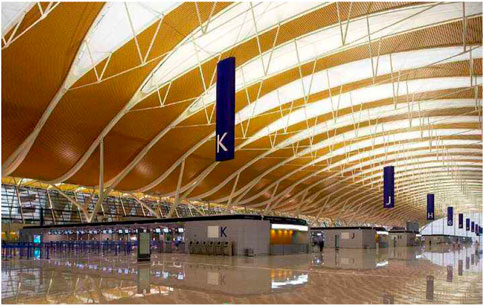
FIGURE 2. T2 terminal for Shanghai Pudong International Airport.
In addition to the traditional beam string structure, new variants are also emerging. For example, the Swiss Montreux parking lot was built in 2004, and the British Lawn Tennis Association tennis court was built in 2010 using a gas-supported string structure. The upper part of the structure uses rigid rods, the middle part uses low-pressure inflatable airbags instead of traditional struts, and the lower chord uses tension cables.
The tension degree of the cable, which is the main force-bearing member of the structure, directly determines the overall stiffness and structural safety of the string structure. Therefore, real-time monitoring of the cable force during the construction and service periods is essential to ensure the safety of the cable structure. To avoid accidents, Structural Health Monitoring (SHM) for monitoring and evaluation of completed cable structures has emerged and has been implemented worldwide (BrownjohnPines and Aktan, 2002; Yun et al., 2003;, 2007). According to current research data, cable force detection methods mainly include the magnetic flux method (Cappello et al., 2018; Duan et al., 2015; Fabo et al., 2002), the strain gauge method (Volokhov et al., 2016; Moradi and Sivoththaman, 2013) and the vibration method (Furukawa et al., 2022; Ma et al., 2021; Kangas et al., 2012; Fang and Wang, 2012; Mehrabi, 2006).
The vibration method has become one of the most commonly used cable force testing methods in engineering because of advantages such as repeatable installation and use at any time, monitoring cost, high measurement result accuracy, simple instrument operation, and convenient practical application. However, there are two factors that affect the accuracy of the cable force test results during the implementation of this method. One is the test accuracy of the natural vibration frequency of the cable segment, and the other is the accuracy of the conversion relationship between the natural vibration frequency and the cable force (Geier et al., 2006). The degree of accuracy is closely related to the degree of model simplification. The more the calculation model conforms to the actual structure, the higher the degree of accuracy. Therefore, research into the vibration method has been an evolutionary process from simplified model to more and more representative of the actual structure. However, for the problem of cable force identification of cable segments, the single-cable model is the most used in engineering and theoretical research, and the research on cable force identification is also based on the single-cable model.
In the 18th century, Brook Taylor, D′ Alembert and Daniel Bernoulli put forward the theory of string vibration, and Bernoulli (1732) and Euler (1781) began to study the lateral vibration of strings successively, determining the solution of the vibration frequency. In 1974, Irvine and Caughey began to consider the elasticity of the cable and deeply studied the effect of sag on the in-plane vibration characteristics of the cable but did not consider the bending stiffness. In the subsequent research on bending stiffness, Tadayuki (1994) proposed a method for estimating the cable force by using high-order frequencies, considering the effects of the bending stiffness, sag and inclination of the cable at the same time. He deduced the cable vibration equation considering the bending stiffness of the cable, but the nonlinear equation needs to be solved by computer, which is not convenient for engineering. Hiroshi et al. (1980) proposed a practical formula for the vibration method using the natural frequency of the low-order mode, considering the influence of the bending stiffness and sag effect of the steel cable. Byeong and Taehyo (2007) proposed a new technique to estimate cable tension force from measured natural frequencies. The proposed method is able to simultaneously identify tension force, flexural rigidity, and axial rigidity of a cable system. Furthermore, it is observed that the flexural rigidity of a cable with high bending stiffness is proportional to the applied tension force. Humar (2012) regarded the cable as a beam subjected to axial force, considering the bending stiffness and ignoring the sag effect, and obtained the cable force expression of the cable hinged at both ends by beam theory. Mehrabi and Tabatabai (1998) used a new numerical algorithm to obtain the solution value of the cable under the influence of bending stiffness, sag effect and damping. Zarbaf et al. (2018) proposed a simple novel framework to estimate the cable tension based on Artificial Neural Networks (ANNs). The method takes into account the cable axial stiffness and cable bending stiffness. It was shown that, for the new Ironton-Russell Bridge, using cable length, cable mass per unit length, cable axial stiffness, and the first two cable natural frequencies as input features to ANNs, the cable tensions can be accurately estimated. In a study by Nam and Nghia (2011), the characteristic equation for vibration of the most general case of a cable is analytically derived, where both the sag and flexure in the cable are taken into account. After that, by considering proper simplifying assumptions of the small flexural rigidity parameter, asymptotic forms of that equation were obtained. It renders a practically applicable procedure to estimate cable tension using measured natural frequencies.
As for the boundary conditions, Rebecchi et al. (2013) presented an experimental procedure for the axial load identification of slender prismatic beams with unknown boundary conditions by making use of one vibration frequency and five amplitudes of the corresponding mode shape. Yan et al. (2014) proposed an innovative method for cable force identification which converts constructing and solving the cable motion equation into finding the zero-amplitude point of its mode shape. The results showed that when the modal order is less than 18, the method can achieve a maximum relative error of less than 5% regardless of the boundary conditions at both ends. Syamsi et al. (2022) extended the two-mode frequency approach by introducing equivalent effective length for any mode pairs regardless of the type of end-restraints. To verify the proposed formula, three cases of cable end-restraints (hinged-hinged, fixed-fixed and hinged-fixed) with the same tensioning force and cross-sectional properties were studied.
The single-cable model is convenient and highly efficient in engineering, so the single-cable model is irreplaceable in practical engineering applications. After deriving theoretical formulas and fitting experimental data, researchers proposed a series of empirical formulas based on the single-cable model, considering the simplicity of engineering applications. For example, Hiroshi et al. (1980) gave a series of empirical formulas for cables with different slenderness ratio ranges to meet engineering needs under different conditions. Ricciardi and Saitta (2008) considered the effects of bending stiffness and sag in the formula and proposed a practical formula for continuous cables.
In the above studies, theoretical research is carried out based on the single-cable model for the problem of cable identification. However, the identification accuracy of the single-cable vibration method is very dependent on the accuracy of the basic model of the cable and the assumption of boundary constraints. The string structure is a hybrid structure of rigidity and flexibility, in which the end restraint stiffness of the cable members is related to the distribution of the cable force. Therefore, the constraints of the cable are difficult to determine. Moreover, many cables exist in actual engineering in the form of continuous and multi-strand cables, so the cable model’s bending stiffness and boundary constraints that are assumed to be in the form of single cables may deviate greatly from the actual situation. In order to use the assumption of the single-cable model to improve efficiency, we believe that it is necessary to improve the accuracy of the cable force identification results based on the single-cable model for the tensioned string structure.
To make the cable force identification of the string structure more accurate by using the single-cable model, this paper intends to conduct a modal analysis of the overall structure of the string beam by means of finite element numerical simulation and theoretical analysis. The three-stage criterion method is proposed and used to obtain the local modal information of the cable under the influence of the overall structure. After mastering the real local vibration characteristics of the cable, the difference between the cable force identification results based on the vibration method are compared with the design cable force based on the assumption of a single-cable model. This method can be used to study the magnitude of the error caused by the calculation of the cable force of the tension-string structure based on the single-cable model assumed with different boundary conditions. The three-stage criterion is beneficial to put forward suggestions for improving the cable force identification accuracy of the vibration method single-cable model of the existing string structure. It will enable the single-cable model assumption to be used to simultaneously improve the efficiency and ensure the solution accuracy. The work of this paper is a useful discussion on the identification of the vibration method of complex cable systems, such as the beam string structure.
The principle of the vibration method is to 1) use a vibration converter to pick up the vibration signal of the cable that has received artificial excitation or environmental excitation; 2) analyze and process the vibration signal to obtain the natural vibration frequency of the cable; 3) calculate the cable force according to the relationship between the cable force and the natural vibration frequency. The string model and beam model are the main existing cable force identification models for a single cable.
For slender cables with small cross-sectional areas and large lengths, the influence of bending stiffness, sag and other factors on the cable force can be ignored, so the tensioned string model can be used to calculate the cable force (Irvine et al., 1974). The more commonly used classical cable force theory formula for this model is shown in Eq 1:
In Eq 1, m is the mass per unit length [kg/m];
For short and thick cables with large cross-sections and small lengths, in order to meet the requirements of cable force identification accuracy, their bending stiffness must be considered, so it is necessary to use the beam model to calculate cable force (Humar, 2012).
Assuming that the mass, m, per unit length of the beam is constant and the bending stiffness, EI, is also constant, the free vibration equation is:
Considering the hinged condition at both ends, the theoretical formula for calculating the cable force is shown in Eq 3:
The boundary conditions of the cable segment in the beam string structure are closer to those of the articulated boundary conditions at both ends. Therefore, the error comparison is made on the basis of the hinged connection, so only the hinged condition is introduced in this paper.
In order to calculate conveniently, basic assumptions should be made for the beam string structure according to its mechanical characteristics:
1. It is assumed that the connection point between the cable segment and the strut is an ideal hinge, and the connection nodes are completely coincident.
2. The cable has been kept in working condition, only under tension, not loose.
3. The cable segment is a straight-line element.
4. Within a small time period, the cross-sectional area of the strut and beam elements remains unchanged.
The undamped free vibration equation of the string structure is:
Where
After the static analysis of the structure is completed, the static equilibrium position of the string structure is obtained. In the dynamic analysis, the internal force and geometric coordinates of the static equilibrium position of the system are selected as the initial state of the dynamic analysis. That is, the system is assumed to vibrate slightly at the static equilibrium position.
For a linear system, the particular solution of Eq 4 is:
where
Substituting Eq 5 into Eq. 4, after derivation, we can get:
where
The dynamic analysis of the string structure system can be reduced to the generalized eigenvalue problem of Eq 6. The calculation methods mainly include the Block Lanczos method and the Subspace method. Among them, the Block Lanczos method eigenvalue solver is the default solver of ANSYS modal analysis, which uses the Lanczos algorithm, which in turn uses a set of vectors to realize the Lanczos recursive calculation. This method has the same accuracy as Subspace but is faster. The Block Lanczos method will be used in the calculation in this paper.
This paper uses ANSYS software, using APDL language to write command flow, and establishes a beam string structure model for numerical simulation analysis.
The steel beam part of the beam string structure model is simulated by the 3-D linear finite-strain beam element Beam188. It is a two-node three-dimensional linear beam element, which can be defined by commands such as SECTYPE, SECDATA, and SECOFFSET to meet the actual section shape, and has 6 or 7 degrees of freedom on a single node. The beam element is calculated based on Timoshenko beam theory and is well suited to linear analysis and nonlinear analysis of large stress.
The strut part of the beam string structure model is simulated by the Link180 element. The Link180 is a 3-D element which is useful in a variety of engineering applications, for trusses, sagging cables, links, springs, and more. The element is a uniaxial tension-compression element with three degrees of freedom at each node: translation in the x, y, and z directions of the nodes, with plasticity, creep, rotation, large deflection, and large strain capabilities.
The cable part in the beam string structure model is simulated by the Beam189 element; a 3-D quadratic three-node beam element. With default settings, each node has 6 degrees of freedom. The element is based on Timoshenko beam theory and is well suited for linear, large rotation, large strain nonlinear applications. In this paper, it is considered that the cable in the tensioned beam string structure is used as a short cable, and its flexural rigidity cannot be ignored. Therefore, compared with the Link10 element, the Beam189 beam element can more accurately simulate the cable in the tensioned beam string structure.
In ANSYS, two methods, the initial strain method or the cooling method, are usually used to simulate the prestress. The former applies initial strain to the cable element and the prestress is applied by pretensioning or precompressing the line element; the latter applies temperature load to the cable element and the prestress is applied by heating or cooling. In this paper, the Beam189 element is used to simulate the prestressed cable, which can easily apply prestressing through the INISTATE command. Therefore, the initial strain method is selected to apply prestress to the cable.
The number of element divisions of the finite element model has a great influence on the accuracy of the calculation results. If the number of cable element divisions is too small, the error of the calculation results will be too large, which will not meet the accuracy requirements. By establishing a single-cable model, we divide a single cable into different numbers of elements. The error between the frequency results of finite element simulation and the theoretical solution under different element division conditions were calculated, and then the number of elements that can meet the accuracy requirements of the simulation were obtained. The “error” here means the frequency difference between the theoretical solution and the finite element simulation analysis result of a same single cable.
The comparison data is shown in Figure 3.

FIGURE 3. Influence of different number of element divisions on calculation error.
Figure 3 shows that with the increase of the number of element divisions, the error of the ANSYS frequency calculation result gradually decreases; from the high-order frequency to the low-order frequency, the error gradually decreases. When the number of element divisions increases to 100, the error between the model’s first 8-order modal frequency results and the theoretical solution frequency tends to be stable. If the number of element divisions continues to increase, the error does not change much. At the same time, according to the condition that the calculation errors of low-order and high-order frequencies are both less than 0.3%, it can also be considered that the number of unit divisions must be 100 to meet the accuracy requirements of numerical calculation results. The computational cost can be minimised compared to the number of more unit divisions. Therefore, in the subsequent calculation, we uniformly divide each cable segment by 100 elements.
By performing modal analysis on the overall structure of the beam string structure, all the mode shapes and frequency information of the overall structure can be obtained. Among these modes, there are some where the entire structure vibrates, and some where only the cables vibrate locally. Among so many modes, if the local mode of a cable can be found, the corresponding frequency is the nth-order vibration frequency of the cable considering the influence of the overall structure; the corresponding mode shape is the nth-order mode shape of the cable considering the influence of the overall structure.
Based on the local cable vibration modes identified in the global modes, the cable force identification results can be obtained from the single-cable model assumption based on the vibration method. Hence, by comparing the difference between the obtained cable force identification results and the design cable force, the error size of the cable force identification can be studied and corrections can be suggested. Then it is possible to use the assumption of the single-cable model to improve the efficiency while ensuring the accuracy of the solution. Therefore, this paper proposes a three-stage criterion for local modal extraction of beam string structure to identify local modal information.
To determine which cable segment is the main vibration of a certain order vibration, we adopt the following criterion: find the node corresponding to the maximum amplitude and the cable segment where the node is located by means of APDL command flow.
ANSYS software has powerful post-processing capabilities. Using APDL language to write a program, the modal analysis results of the beam string structure, including each order mode shape diagram, vibration frequency, mode shape data, etc., can be exported to image or text format. Furthermore, the maximum amplitude of the node can be obtained from the command flow, and the cable segment where the node is located can be found to judge that the mode belongs to the main mode of a certain cable segment.
While criterion 1 identifies whether a certain cable segment is the order mode’s main vibration cable segment, criterion 2 determines whether this order mode must be the local vibration of this cable segment. Thus, the second criterion is used to make the following judgments:
1 When the length of the cable segment differs greatly, the amplitude of the cable segment is the largest, and the amplitude of each node of the other cable segments is 0 or very small, which can be determined as a local mode of a certain order of the cable segment.
2 When the length of the cable segment is similar, except for the similar cable segment, the amplitude of the cable segment is the largest, and the amplitude of each node of the other cable segment is 0 or very small, it can be determined as a local mode of a certain order of the cable segment.
When we use criterion 2 to determine that a certain overall mode is a local mode of a certain cable segment, we still need to determine which mode of the cable segment corresponds to this mode. To this end, the third criterion is introduced: based on the Modal Assurance Criterion (MAC) value, the modal order of the cable segment where the maximum amplitude is located is determined.
The mode shape vector data exported from ANSYS is imported into MATLAB software, and the modal order of the cable segment where the maximum amplitude is located is judged based on the concept and function of the MAC.
The MAC is a common tool for evaluating structural dynamic characteristics. It is used to evaluate the degree of correlation between two sets of mode shape vectors.
The definition of MAC is shown in Eq 7:
Where
In this paper, using the overall structure calculation of the string beam, a finite element analysis model is established. The mode shape vector of the cable segment where the maximum amplitude is located is obtained through analysis. Then a single-cable finite element model with hinged ends is established to obtain the reference vector,
To show the effectiveness of the method in this paper and show the regularity of the research more intuitively, a simple beam string structure is selected as an example. The beam element section is a circular pipe with an inner radius of 95.5 mm and an outer radius of 101.5 mm; the strut element has a circular section with a sectional area of 234 mm2; the cable element has an equivalent sectional area of 346 mm2. The bending stiffness of the cable in this EI = 1810.072351 Nm2, and the mass per unit length is 2.72 kg/m. The elastic modulus of beam and strut steel is 2.06e5 MPa, and the elastic modulus of cable steel is 1.9e5 MPa. The bending stiffness value here is a design value. If it is applied in practice, the cable factory will provide the actual value. The cables at the bottom of the beam string structure are numbered in sequence and the dimension of the beam string structure model is shown in Figure 4.
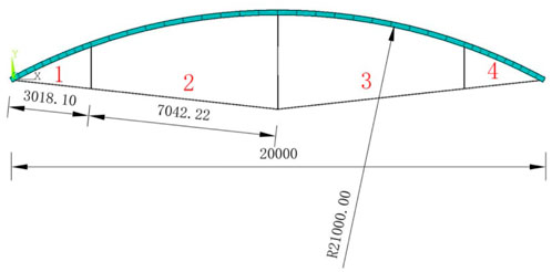
FIGURE 4. The serial number of cables and diagram of the beam string structure model [dimensions are in mm].
1 Build the model—the beams, rods, and cables of the beam string structure are selected as described in the previous section and the data files of the finite element model of the beam are written in APDL language, including element, material, and section information, mesh division, etc. The various information requested is defined using the LATT command. The LESIZE command is used to specify that the number of elements to divide the cable is 100, and the LMESH command is used to divide the mesh.
2 Constraints—Set the left end of the beam string structure as a fixed hinge and the right end as a sliding hinge. The Z-direction displacement of all nodes is constrained to be 0 and only the in-plane vibration of the beam is considered, the out-of-plane space vibration of the beam is not considered.
3 Static analysis—use the command flow “ANTYPE,0” to enter the static analysis solution, apply prestress to the cable using the initial strain method described in the previous section, turn on the large deformation switch and the acceleration of gravity, and calculate the initial state of the beam string structure.
4 Modal analysis—use the command flow “ANTYPE,2” to enter the modal analysis solution, turn on the prestress switch, and solve the first 12 order modal information.
5 Post-processing—write APDL program, and derive the mode shape diagram, mode shape vector and natural frequency required in this paper according to the requirements.
The modal analysis of the overall structure of the beam string structure is used to obtain the first 12-order mode shapes, as shown in Figure 5.
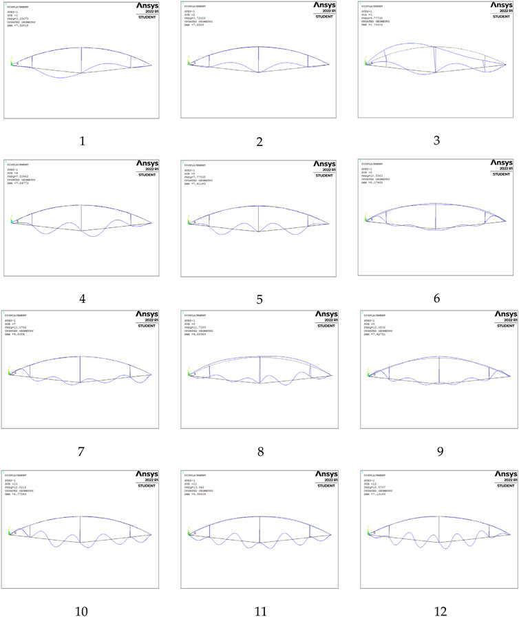
FIGURE 5. 1st to 12th mode shapes.
According to the model information, cable segment 1 contains node numbers 45–243, cable segment 2 contains node numbers 344–542, cable segment 3 contains node numbers 942–1,140, and cable segment 4 contains node numbers 643–841.
This article will take the No. 3 cable section as an example to introduce the criterions. For example, the maximum amplitude node number of the first mode is 1,037, which belongs to the No. 3 cable segment, and other rigid members have almost no amplitude. Except for the cable segments of similar length, the other cable segments also have almost no amplitude. Thus the overall mode of order 1 is considered to be the local mode of cable segment 3. The cable segments corresponding to other modal information are shown in Table 1. However, some of the overall modes are not only the vibration of the cable part, but also the vibration of beams or struts, such as the third-order overall mode. Such modes need to be eliminated and cannot be used as calculation samples. For the simple beam string model, this step can be roughly judged by visual inspection. For the complex string beam structure, it is necessary to compile a common program for accurate judgment.
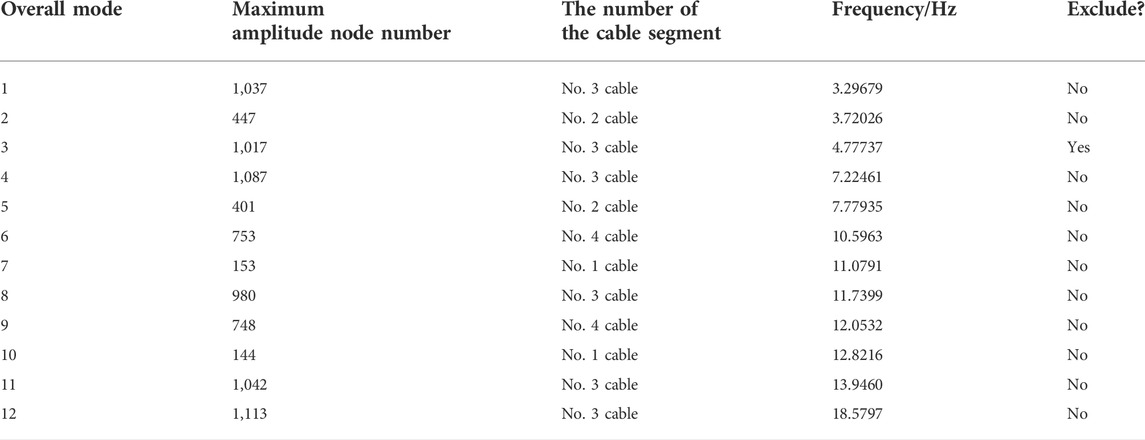
TABLE 1. Overall modal information and corresponding cable segment number.
For example, for the overall first-order mode mentioned in the previous section, the corresponding maximum amplitude cable segment is the No. 3 cable, and then it needs to be determined as the order of the local vibration of the No. 3 cable. A single-cable model was established based on APDL language as a reference, and the boundary condition of the single-cable was hinged at both ends. The ANSYS modal analysis calculation was performed and the first 4-order mode shape vector text data was exported as a reference. In this paper, the No. 3 cable is selected as the calculation object, and some MAC values are given as shown in Table 2.
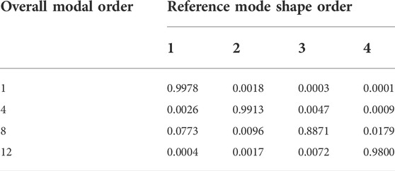
TABLE 2. Calculation results of the MAC value of the No. 3 cable.
Table 2 shows that the first order of the overall modes corresponds to the first order of the local vibration of the No. 3 cable; the fourth order of the overall modes corresponds to the second order of the local vibration of the No. 3 cable; the eighth order of the overall modes corresponds to the third order of the local vibration of the No. 3 cable; the 12th order of the overall mode corresponds to the fourth order of local vibration of No. 3 cable.
After the comparison and analysis of the data in the previous section, it can be found that under the influence of the overall structure of the beam string structure of No. 3 cable segment, its local first-order frequency is the first-order frequency of the overall mode, which is 3.296793 Hz; its local second-order frequency is the overall modal frequency. The frequency of the 4th order is 7.224617 Hz; the frequency of the local 3rd order is the frequency of the 8th order of the overall mode, which is 11.7399 Hz; the frequency of the local 4th order is the frequency of the 12th order of the overall mode, which is 18.5797 Hz.
The vibration frequency of the local cable segment extracted from the overall structure is compared with the frequency of the single-cable theoretical solution. The local frequency of the cable segment extracted by the method in this paper is compared with the frequency of the single-cable theoretical solution in Table 3; the frequency errors for the 1st to 4th orders are also presented.
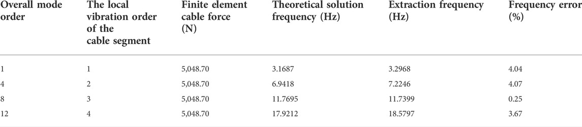
TABLE 3. Comparison of extraction frequency and theoretical frequency.
The extracted frequency is very close to the theoretical solution frequency from the local modal information extracted from the overall mode using the three-stage criterion proposed in this paper, indicating that the method proposed in this paper is effective. The reason for the difference is that the cable segment in the beam string structure is not a single-cable model with hinged ends. The specific size and modification suggestions of this part of the error will be given in our follow-up research work.
Substituting the extracted first four-order local frequencies into the classical formula for single-cable force identification, the errors between the cable force and the finite element design cable force are 8.84%, 10.69%, 0.82%, and 16.03%, respectively, as shown in Table 4.
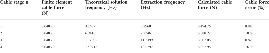
TABLE 4. Comparison of cable force results between extraction frequency and theoretical frequency.
If the cable force identification of the tension beam string structure is based on the single-cable test method commonly used at present, it will inevitably cause identification errors. This part of the error is caused by the influence of the overall structure of the beam string structure. When we know the size of the error, it can be corrected in the actual test to improve the calculation efficiency and ensure the accuracy of the solution.
After analysis and comparison of examples, the method proposed in this paper is used to extract the local vibration modal information of the cable in the overall mode. The mode shape and frequency are consistent with the theoretical solution of the single cable, but there are certain differences due to the influence of the overall structure. The numerical example proves the effectiveness of the method for extracting the vibration modal information of the local cable presented in this paper.
The main work of this paper is discussed as follows:
1 An ANSYS dynamic analysis model of the beam string structure is established based on APDL language. Comparing multiple sets of data, it is found that when the number of element divisions in the cable modeling process is 100, it can better balance the common needs of calculation accuracy and calculation time cost.
2 A three-stage criterion for automatic identification of the local mode of the cable in the beam string structure is proposed. Criterion 1: Find the main vibration cable segment according to the maximum amplitude node. Criterion 2: When the cable length and other parameters of the cable segments differ greatly, the cable segment with the largest amplitude is the main vibration cable segment. In addition, if there is no other rigid member vibrating or the amplitude is small, it can be determined that the overall mode is the local mode of the cable segment. When the parameters such as the cable length of the cable segment are similar, except for the similar cable segment, the amplitude of the cable segment is the largest, and the amplitude of each node of the other member and cable segment is 0 or very small, it can be determined as a local mode of a certain order of the cable segment. Criterion 3: Use the Modal Assurance Criterion (MAC) to evaluate the correlation between the local mode shape and the reference mode shape and obtain the local mode order corresponding to the main vibration cable segment.
3 After obtaining the local modal information of the cable of the beam string structure through the three-stage criterion, there is a certain error between the cable force identification result from on the vibration method based on the single-cable model and the actual cable force. The magnitude of the error reflects the influence of the overall structure on the vibration characteristics of the cable segment; the magnitude of the influence depends on factors such as the structural form, member stiffness, and cable force distribution. In the follow-up work, we will further use the method proposed in this paper to study the cable force identification error of the vibration method using the single-cable model of different types of string structures and propose a systematic correction scheme.
4 In practical application, for the specific beam string structure model, numerical analysis can be carried out by the method in this paper, and the size of the influence of each cable segment by the overall structure can be analyzed, so as to guide the correction of actual results and improve the accuracy of cable force identification.
The original contributions presented in the study are included in the article/supplementary material, further inquiries can be directed to the corresponding author.
Corresponding author YZ proposed the work idea of this paper, analyzed and guided the results of the paper, and reviewed and revised the article. The first author, TZ, is responsible for the use and calculation of finite element software, and writes the first draft. HZ is responsible for reviewing and modifying English expressions.
Major Project of Shanghai Science and Technology Commission (Grant number: 1323050300).
The authors declare that the research was conducted in the absence of any commercial or financial relationships that could be construed as a potential conflict of interest.
All claims expressed in this article are solely those of the authors and do not necessarily represent those of their affiliated organizations, or those of the publisher, the editors and the reviewers. Any product that may be evaluated in this article, or claim that may be made by its manufacturer, is not guaranteed or endorsed by the publisher.
Brownjohn, J. M. W. (2007). Structural health monitoring of civil infrastructure. Phil. Trans. R. Soc. A 365 (1851), 589–622. doi:10.1098/rsta.2006.1925
Byeong, H. K., and Taehyo, P. (2007). Estimation of cable tension force using the frequency-based system identification method. J. Sound. Vib. 304 (3-5), 660–676. doi:10.1016/j.jsv.2007.03.012
Cappello, C., Zonta, D., Ait Laasri, H., Glisic, B., and Wang, M. (2018). Calibration of Elasto-Magnetic Sensors on In-Service Cable-StayedBridgesfor Stress Monitoring. Sensors 18 (2), 466. doi:10.3390/s18020466
Chen, Y., Shen, Z., Zhao, X., and Chen, Y. (1999). Experimentalstudy on a full-scale roof truss of Shanghai Pudong international airport terminal. J. Build. Structures 20 (2), 9–17. doi:10.14006/j.jzjgxb.1999.02.002
Duan, Y., Zhang, R., Dong, C., Luo, Y., Or, S. W., Zhao, Y., et al. (2015). Development of elasto-magneto-electric (EME) sensor for in-service cable force monitoring. Int. J. Str. Stab. Dyn. 16 (4), 1640016. doi:10.1142/S0219455416400162
Fabo, P., Jarosevic, A., and Chandoga, M. (2002). Health monitoring of the steel cables using the elasto-magnetic method. ASME Int. Mech. Eng. Congr. Expo. 36258, 295–299. doi:10.1115/IMECE2002-33943
Fang, Z., and Wang, J. (2012). Practical formula for cable tension estimation by vibration method. J. Bridge Eng. 17 (1), 161–164. doi:10.1061/(ASCE)BE.1943-5592.0000200
Furukawa, A., Suzuki, S., and Kobayashi, R. (2022). Tension estimation method for cable with damper using natural frequencies with uncertain modal order. Front. Built Environ. 8, 812999. doi:10.3389/fbuil.2022.812999
Geier, R., De Roeck, G., and Flesch, R. (2006). Accurate cable force determination using ambient vibration measurements. Struct. Infrastructure Eng. 2 (1), 43–52. doi:10.1080/15732470500253123
Hiroshi, Z., Tohru, S., and Yoshio, N. (1980). Practical formulas for estimation of cable tension by vibration method. J. Struct. Eng. 122 (6), 651–656. doi:10.1061/(ASCE)0733-9445
Irvine, H. M., and Caughey, T. K. (1974). The linear theory of free vibration of a suspended cable. Proc. R. Soc. Lond. 341 (1626), 299–315. doi:10.1098/rspa.1974.0189
Kangas, S., Helmicki, A., Hunt, V., Sexton, R., and Swanson, J. (2012). Cable-stayed bridges: Case study for ambient vibration-based cable tension estimation. J. Bridge Eng. 17 (6), 839–846. doi:10.1061/(ASCE)BE.1943-5592.0000364
Ma, L., Xu, H., Munkhbaatar, T., and Li, S. (2021). An accurate frequency-based method for identifying cable tension while considering environmental temperature variation. J. Sound. Vib. 490, 115693. doi:10.1016/j.jsv.2020.115693
Mehrabi, A. B. (2006). In-service evaluation of cable-stayed bridges, overview of available methods and findings. J. Bridge Eng. 11 (6), 716–724. doi:10.1061/(asce)1084-0702(2006)11:6(716)
Mehrabi, A. B., and Tabatabai, H. A. (1998). Unified finite difference formulation for free vibration of cables. J. Struct. Eng. (N. Y. N. Y). 124 (11), 1313–1322. doi:10.1061/(asce)0733-9445(1998)124:11(1313)
Moradi, M., and Sivoththaman, S. (2013). Strain transfer analysis of surface-bonded MEMS strain sensors. IEEE Sens. J. 13 (2), 637–643. doi:10.1109/JSEN.2012.2225043
Nam, H., and Nghia, N. T. (2011). Estimation of cable tension using measured natural frequencies. Procedia Eng. 14, 1510–1517. doi:10.1016/j.proeng.2011.07.190
Pines, D., and Aktan, A. E. (2002). Status of structural health monitoring of long-span bridges in the United States. Prog. Struct. Engng. Mat. 4 (4), 372–380. doi:10.1002/pse.129
Qin, J., Chen, X., and Xu, R. (2007). Design and experimental study on the joints of Nation Gymnasium. Ind. Const. 37 (1), 12–15. doi:10.1016/S1872-2032(07)60057-2
Rebecchi, G., Tullini, N., and Laudiero, F. (2013). Estimate of the axial force in slender beams with unknown boundary conditions using one flexural mode shape. J. Sound. Vib. 332 (18), 4122–4135. doi:10.1016/j.jsv.2013.03.018
Ricciardi, G., and Saitta, F. (2008). A continuous vibration analysis model for cables with sag and bending stiffness. Eng. Struct. 30 (5), 1459–1472. doi:10.1016/j.engstruct.2007.08.008
Saitoh, M., and Okada, A. (1999). The role of string in hybrid string structure. Eng. Struct. 21 (8), 756–769. doi:10.1016/S0141-0296(98)00029-7
Sun, W. B., Yang, S. Y., and Chen, R. Y. (2003). Stiffness performance of truss-string structure of Guangzhou international convention and exhibition center. J. South China Univ. Technol. Sci. 31 (11), 33–36. doi:10.1007/s11769-003-0044-1
Syamsi, M. I., Wang, C. Y., and Nguyen, V. (2022). Tension force identification for cable of various end-restraints using equivalent effective vibration lengths of mode pairs. Measurement 197, 111319. doi:10.1016/j.measurement.2022.111319
Tadayuki, S. (1994). Estimating method of cable tension from natural frequency of high mode. Dob. Gakkai Ronbunshu 501, 163–171. doi:10.2208/jscej.1994.501_163
Volokhov, I. V., Gurin, S. A., and Vergazov, I. R. (2016). Study of the properties of high-sensitivity thermally-stable thin-film resistance strain gauges for integral pressure sensors. Meas. Tech. 59 (1), 80–86. doi:10.1007/s11018-016-0921-5
Wang, D. S., Zhou, J., Liu, C. Y., and Zhang, F. L. (2007). Design and research on roof structure of Pudong international Airport terminal 2. Build. Struct. 37 (5), 45–49. doi:10.1007/s10870-007-9222-9
Yan, B., Yu, J., and Soliman, M. (2014). Estimation of cable tension force independent of complex boundary conditions. J. Eng. Mech. 141 (1), 6014015. doi:10.1061/(ASCE)EM.1943-7889.0000836
Yun, C. B., Lee, J. J., and Kim, S. K. (2003). Recent R&D activities on structural health monitoring for civil infra-structures in Korea. Ksce J. Civ. Eng. 7 (6), 637–651. doi:10.1007/BF02829136
Keywords: beam string structure, vibration method, cable tension identification, local modes, spatial structure
Citation: Zhang T, Zhang Y and Zhang H (2022) A three-stage criterion method for extracting local vibration modes of tensioned cables in beam string structures. Front. Mater. 9:1055635. doi: 10.3389/fmats.2022.1055635
Received: 28 September 2022; Accepted: 11 October 2022;
Published: 21 October 2022.
Edited by:
Liang Ren, Dalian University of Technology, ChinaCopyright © 2022 Zhang, Zhang and Zhang. This is an open-access article distributed under the terms of the Creative Commons Attribution License (CC BY). The use, distribution or reproduction in other forums is permitted, provided the original author(s) and the copyright owner(s) are credited and that the original publication in this journal is cited, in accordance with accepted academic practice. No use, distribution or reproduction is permitted which does not comply with these terms.
*Correspondence: Yuxin Zhang, enl4QHNobnUuZWR1LmNu
Disclaimer: All claims expressed in this article are solely those of the authors and do not necessarily represent those of their affiliated organizations, or those of the publisher, the editors and the reviewers. Any product that may be evaluated in this article or claim that may be made by its manufacturer is not guaranteed or endorsed by the publisher.
Research integrity at Frontiers
Learn more about the work of our research integrity team to safeguard the quality of each article we publish.