 Su-Juan Liu1,2
 Di Wang
94% of researchers rate our articles as excellent or good
Learn more about the work of our research integrity team to safeguard the quality of each article we publish.
Find out more
ORIGINAL RESEARCH article
Front. Mater., 25 August 2021
Sec. Quantum Materials
Volume 8 - 2021 | https://doi.org/10.3389/fmats.2021.739449
This article is part of the Research TopicLight-Nanomaterial Interactions for Energy Efficient Nanophotonic DevicesView all 10 articles
In this paper, we propose a holographic near-eye 3D display method based on large-size computer-generated hologram (CGH). The reconstructed image with a large viewing angle is obtained by using a time multiplexing and spatial tiling system. The large-size CGHs are generated and they record the information of the 3D object from different angles. The CGHs are reproduced at different moments. For a certain reconstructed moment, three spatial light modulators (SLMs) spatially spliced into a linear structure are used to load a single CGH. The diffraction boundary angle of the reconstructed light forming each image point is equal to the maximum diffraction angle of the SLM, so the viewing angle of the image generated by the CGH is enlarged. For different CGHs, the incident angle of reconstructed light is changed. Through time multiplexing, the reconstructed images of the CGHs are combined into a reconstructed image whose viewing angle is further enlarged. Due to the large viewing angle of the reconstructed image, the proposed method has unique advantages in near-eye display. The feasibility of the proposed method is proved by experimental results.
Holographic near-eye display technology is based on the user’s observation of the real world, and can continuously provide virtual holographic image information for the user, to realize the function of real-time interaction between the real and the virtual environment (Azuma, 1997; Chen and Chu, 2015; Lee et al., 2019). It is widely used in many fields such as military, medical, education and entertainment (Choi et al., 2021; Wang et al., 2021). Recently, due to the realistic effect of the computer-generated holographic near-eye display, a series of researches on this technology have been implemented. However, this technology has some problems hindering its further development. Among them, the maximum diffraction angle of the reproduced light is only a few degrees (Senoh et al., 2011; Li et al., 2020; Liu et al., 2020; Wang et al., 2020). This is because the pixel size of currently available spatial light modulators (SLMs) is on the micron level, which is an order of magnitude larger than the light wavelength. Accordingly, the viewing angle of the holographic image is narrow and not suited for binocular observation. Therefore, in order to increase the practicality of the holographic display, some methods to improve this problem have been proposed. For example, the viewing angle is expanded through time multiplexing to combine the high-order reconstructed beams temporally (Mishina et al., 2002). In the equivalent-curved-SLM-array method, the viewing angle can be increased to 13.5° by superimposing different linear phase factors on one phase SLM sequentially (Liu et al., 2013). In the resolution redistribution method, the horizontal resolution of the SLM is increased several times through a 4f imaging system (Takaki and Hayashi, 2008; Takaki and Tanemoto, 2010; Takaki and Nakamura, 2011). The multi-channel scanning method uses multiple projection systems and a planar scanner to obtain a large size and large viewing angle reconstruction (Takaki et al., 2015; Takaki and Nakaoka, 2016). The convex parabolic mirror method obtains a reconstructed image with a horizontal viewing angle of 180° (Sando et al., 2018). The reconstructed system of the above methods is relatively simple, and a single SLM is used to load the computer-generated hologram (CGH). However, in order to expand the viewing angle, they may put a higher demand on the refresh rate of the SLM, or reduce other performance of the reconstructed image. In addition, some methods of using multiple SLMs to expand the viewing angle of the image are proposed. In the curved-SLM-array method, some SLMs with a curved arrangement structure are used to increase the numerical aperture of the optical system, thereby expanding the viewing angle (Hahn et al., 2008; Yaras et al., 2011; Kozacki et al., 2012a; Zeng et al., 2017). Through the analysis of the Wigner distribution function, the viewing angle is increased using six SLMs (Kozacki et al., 2012b). The viewing angle of the reconstructed image can be increased to 12.8° by using a 4f concave mirror system and two SLMs (Zeng et al., 2017). These methods can obtain reconstructed images with large viewing angles, but the optical systems are relatively complex. Therefore, they are difficult to operate and high cost, which are not conducive to practical applications.
In this paper, we propose a method to enlarge the viewing angle of the holographic image. The information of different angles of the object is recorded as CGHs. The size of each CGH is increased. In the process of holographic reconstruction, three SLMs arranged in a linear structure are used to load the CGHs. After the spatial splicing effect of the SLMs and the time multiplexing of the reconstructed images in different directions, the viewer finally obtains a large viewing angle holographic reconstructed image. The method is simple and easy to operate, and can be applied to near-eye display technology.
The schematic diagram of the proposed method is shown in Figure 1. The viewing angle of the reconstructed image is enlarged based on the large-size CGHs. The CGHs record the information of the 3D object from different angles. In the holographic reconstruction, three SLMs in a linear configuration are used to load the CGHs. Moreover, it ensures that the incident angle of the reproduced light varies with the CGH. Finally, the reconstructed image is obtained through time multiplexing. Next, we will introduce the theory of the proposed method in detail.
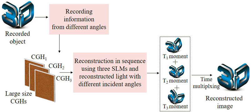
FIGURE 1. Schematic diagram of the proposed method.
First of all, the information of three different angles of the object is recorded as a large-size CGH. We assume that the origin of the coordinate is at the center of the CGH. The size of the recorded object is D. The distance between the object and the CGH is L. The size of the SLM is H and its pixel size is p. For any object point I(x0, L), its information is recorded as an interferogram. The size of the interferogram in the traditional method is equal to the size of the SLM. The CGH is generated by superimposing all the interferograms. During reproduction, a single SLM is used to load the CGH. The light distribution of the reconstructed image can be seen in Figure 2. Based on the property of the field of view (FOV), the FOV is the overlapping area of the light distribution of the leftmost image point A1 and the rightmost image point A2, and the corresponding angle is the viewing angle. The light with the diffraction angle range of [-α, φ] reconstructs the image point A1, and the light with the diffraction angle range of [-φ, α] reconstructs the image point A2. According to the geometric relationship, α and φ can be calculated as follows:
where φ is the allowable maximum diffraction angle of the CGH. If the wavelength of the reconstructed light is denoted as λ, the diffraction angle φ is expressed as follows:
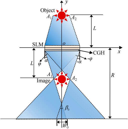
FIGURE 2. Light distribution of the reconstructed image.
It can be seen from Figure 2 and Eqs 1, 2 that the diffraction boundary angle forming any image point cannot reach φ at the same time. Therefore, the viewing angle of the phenomenon is relatively small, which satisfies Eq. 4:
The width of the FOV at the viewing distance R can be calculated according to Eq. 5:
The three recording angles of the object are denoted as left, center, and right angles in the proposed method. In the process of CGHs generation with different angles, the incident angle of the reference light will also change accordingly, as shown in Figure 3. For the sake of simplicity, we take the center recording angle as an example to introduce. The size of the interferogram of any object point is increased. The horizontal coordinates of the image points A1 and A2 are denoted as x1 and x2 , respectively, which satisfy the following equations:
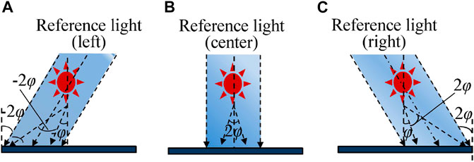
FIGURE 3. Generation of the CGHs at different angles of the proposed method. (A) Reference light (left). (B) Reference light (center). (C) Reference light (right).
The size of the interferogram H1 satisfies Eq. 8:
Then, we add up all the interferograms to generate the CGH. The size of the CGH HCGH is calculated according to Eq. 9:
It can be seen from Eq. 9 that the size of the CGH is increased, which is larger than that of a single SLM and less than the sum size of three SLMs. Therefore, a total of three large-size CGHs are generated from three different recording angles, denoted as the left CGH, the center CGH and the right CGH.
Next, the holographic reconstruction is implemented. In the optical system, three SLMs are arranged in a linear configuration. They are used to load the large-size CGHs. In order to accurately load the CGH onto the SLM, the zero padding is performed on both sides of each CGH. It ensures that the size of the CGH is equal to that of the three SLMs. The CGHs are loaded sequentially for reconstruction. Based on the principle of holographic technology, the direction of reconstructed light is consistent with that of reference light in the CGH. In Figure 4, the light distribution of the reconstructed image is shown. The generation and reproduction of the center CGH are shown in the blue area. According to Eqs 6,7 and the geometric relationship in the reconstructed system, the angle range of the diffraction light generated by any interferogram is [-φ, φ]. Therefore, the light distribution size of each image point is increased accordingly. At the viewing distance R, the viewing angle and the FOV of the image are calculated according to Eqs 10, 11, respectively:
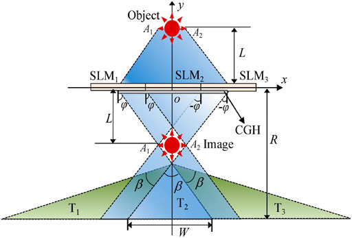
FIGURE 4. Light distribution of the reconstructed image by the proposed method.
Compared with Eqs 4, 5, it shows that the viewing angle and the FOV of the proposed method are obviously enlarged.
In order to ensure the continuity of the FOV of the reconstructed image at different moments, the inclination angles of the reconstructed light of the left CGH and the right CGH are −2φ and 2φ, respectively. In the process of generating the left and right CGHs as shown in Figure 3, the inclination angles of the reference light are also −2φ and 2φ respectively. In Figure 4, the viewing zones generated by the CGHs reconstructed at three different moments are denoted as T1, T2, and T3. After time multiplexing, the viewer can obtain a reconstructed image with continuously distributed viewing angle, where the viewing angle ψ satisfies:
Therefore, we expands the viewing angle of the reconstructed image in one direction by generating the large-size CGH and using the spatial multiplexing of three SLMs. In addition, through time multiplexing, the reconstructed images in three directions are combined into the image with continuous viewing angle, and finally the viewing angle is further expanded to three times.
The feasibility of the proposed method is proved by conducting a series of experiments. The optical reconstructed system is shown in Figure 5. The green laser is used as the reconstructed light, and its wavelength is 532 nm. A collimating system consisting of the laser, filter and lens generates the uniform plane wave. The galvano mirror generates multiple reproduced lights with different incident angles by changing the tilt angle of the mirror. Beam splitter1 divides the reconstructed light into two beams. Among them, the reflected light illuminates SLM1 as the reconstructed light, and the transmitted light continues to propagate forward through beam splitter2 and is also divided into two beams. They are used as the reconstructed light of SLM2 and SLM3 respectively. The three diffracted beams modulated by the SLMs are seamlessly spliced after passing through beam splitter3. Finally, the reconstructed image is obtained on the receiving screen. Three reflective phase-only SLMs provided by Xi’an Institute of Optics and Precision Mechanics have the same parameters. The resolution and size of the SLM are 1,920 × 1,080 and 6.4 μm, respectively. The frame rate is 60 Hz. The phase modulation range is [0, 2π]. In the horizontal direction, the size of the object D and the active area size of the SLM H are 6 and 12.23 mm. Based on Eq. 3, the maximum diffraction angle of the SLM is 2.4°. We record the object’s information into the CGH from the left, center, and right angles respectively. The recorded distance L is set to 220 mm. In order to achieve the continuity of the viewing angle of the reconstructed image, the corresponding incident angles of the reference light are −4.8°, 0° and 4.8°. In each recording direction, according to Eqs 6, 9, the size of the interferogram and the CGH are 18.23 and 24.23 mm, respectively.
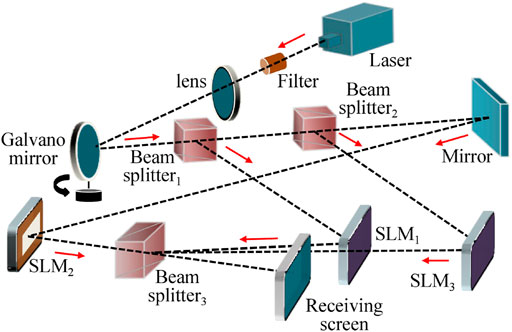
FIGURE 5. Structure of the reconstructed system.
First, we study the reconstructed image of the CGH in one direction. Taking the reproduction of the right CGH as an example, In order to load the CGH accurately, the zero padding and division operations are carried out. In the first step, we perform zero padding operation with the same resolution on the left and right sides of the CGH to make its size equal to the total size of three SLMs. In the second step, the CGH is divided into three parts in the horizontal direction, and the resolution of each part is 1,920 × 1,080. In the third step, according to the arrangement sequence, the three parts of the CGH are respectively loaded onto the SLM for reconstruction. The galvano mirror in the reconstructed system is kept stationary, ensuring that the inclination angle of the mirror is 2.4°, and the incident angle of the reconstructed light is 4.8°. The reconstructed images obtained from two different viewpoints can be seen in Figures 6A,B, respectively. The viewing angle interval between the left and right viewpoints is about 3°. Moreover, in order to conduct comparative analysis of the experiment, the traditional method using a single SLM is implemented. The reconstructed images obtained from the left and right viewpoints are shown in Figures 6C,D, respectively. The experimental results show that the complete images with parallax can be obtained at different viewpoints in the proposed method. However, in the traditional method, only a part of the reconstructed image is obtained from the right viewpoint. These results indicate that the viewing angle of the reconstructed image in one direction is expanded through the generation of the large-size CGH and the spatial splicing of the SLMs.
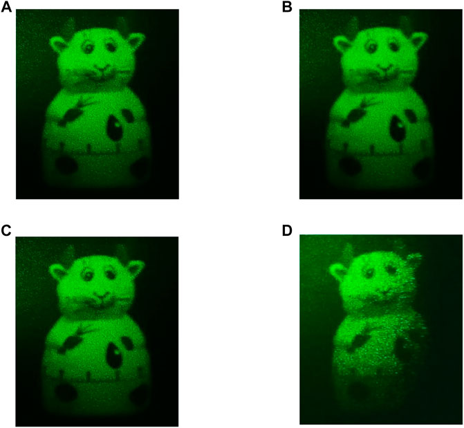
FIGURE 6. Optical reconstructed images obtained from (A–B) the left and right viewpoint of the proposed method, respectively, (C–D) the left and right viewpoint of the traditional method, respectively.
Furthermore, we implement simulation experiments with MATLAB software to record the light distribution of the image points, so as to analyze the FOV of the reconstructed image in one direction, as shown in Figure 7. The light distribution of the leftmost and rightmost image points are represented by the blue and red lines, respectively. In the proposed method, the width of the FOV is 17.2 mm at the viewing distance of R = 500 mm(Figure 7A). The width of the FOV is 1.9 mm in the traditional method (Figure 7B). In contrast, the FOV of the proposed method is enlarged by 8 times. At the viewing distance R= 800 mm, the light distribution are shown in Figure 7C and Figure 7D. Using the proposed method, the width of the FOV is increased by 3 times. The experimental results verify the theoretical values within the allowable error range (Eqs 5, 11). It proves that the proposed method significantly expands the FOV, and as the viewing distance increases, the increase rate of the FOV slows down.
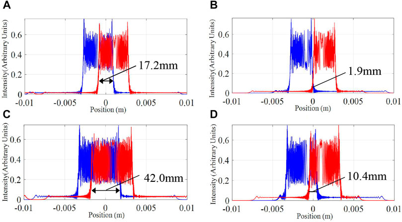
FIGURE 7. Light intensity distribution of the leftmost and rightmost image points of (A) the proposed method at R = 500 mm, (B) the traditional method at R = 500 mm, (C) the proposed method at R = 800 mm and (D) the traditional method at R = 800 mm.
Then, the left, center and right CGHs are reconstructed in time sequence. The incident angle of the reconstructed light is changed by the reflection of the galvano mirror. In the experiment, when the tilt angle of the galvano mirror is set to −2.4°, 0° and 2.4° at different moments, three reconstructed lights with different incident angles are generated correspondingly, which are −4.8°, 0° and 4.8°, respectively. The changing frequency of the CGH and the galvano mirror is kept synchronized to ensure that the incident angle of the reconstructed light is the same as the angle of the reference light in the CGH. The images in the left, middle and right directions are reconstructed at different moments. Within the persistence effect of the human eye, the reconstructed image with a continuous viewing angle is obtained. Viewed from different angles, the reconstructed images can be seen in Figure 8. The complete images from the directions of −7°, −4°, 0°, 4°, and 7° are obtained. Therefore, through time multiplexing of the images in different directions, the reconstructed image with a continuous viewing angle of about 14° is obtained. Compared with the reproduced image in one direction, the viewing angle has been enlarged three times.
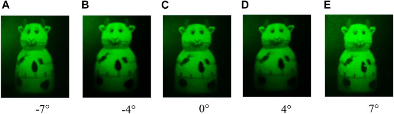
FIGURE 8. Reconstructed images are obtained from (A) left −7° direction, (B) left −4° direction, (C) center 0° direction, (D) right 4° direction and (E) right 7° direction.
The proposed method obtains the reconstructed image with a large viewing angle through a simple optical system, so it can be applied to near-eye display technology. The following experiment is implemented for verification. In the holographic near-eye display system, a beam splitter is used to replace the receiving screen. The reconstructed image is reflected when it passes through the beam splitter. In addition, a little toy is placed aside as a real reference. The distance between the toy and the beam splitter is 500 mm. The beam splitter realizes the fusion of the real object and holographic image. The reconstructed images captured by the camera from different angles are shown in Figure 9. In the left direction (Figure 9A), the left surface of the toy and the reconstructed image has a larger size. In the center viewpoint (Figure 9B), the left and right surfaces have a similar size. In the right viewpoint (Figure 9C), the right surface becomes has a larger size. These results indicate the holographic near-eye display realize a good reproduction effect due to the viewing angle enlargement by using the proposed method.
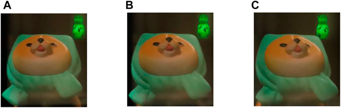
FIGURE 9. Reconstructed images in the holographic near-eye display obtained from (A) left −7° direction, (B) center 0° direction and (C) right 7° direction.
The above experiments confirm that the advantages of the proposed method are outstanding. Based on the generation of the large-size CGHs, combined with the use of time multiplexing and spatial tiling system, the viewing angle of the reconstructed image in the holographic near-eye display has been significantly increased. The optical system of the proposed method is simple and easy to operate, so it has practical application value. However, the proposed method still has some unsolved issues. For example, there is speckle noise caused by laser coherence in the reconstructed image. The denoising algorithms will be studied to improve the image quality without increasing the system’s complexity. In addition, the proposed method only generates reconstructed images with monochrome information. We will use time multiplexing method to obtain the color image. In addition, we record the information of the object in three different directions. The viewing angle of the reconstructed image is increased to about 14°, which is not enough for the free viewing of multiple people. In the proposed method, the viewing angle increases as the number of CGHs increases. So, in the following work, we can increase the recording direction of the object to ensure that the number of generated CGHs is less than the refresh frequency of the SLM. During the reproduction process, within the persistence effect of human eyes, the reconstructed images of different CGHs are combined into one image, and the viewing angle of the image is further increased.
In this paper, we propose a holographic near-eye display method in which the viewing angle is enlarged. The viewing angle of the reconstructed image in one direction is expanded through the generation of the large-size CGH and the spatial splicing of the SLMs. At the viewing distance of R = 500 mm, the FOV is increased by 8 times compared with the traditional method. Then, using time multiplexing of the images in different directions, the reconstructed image with continuous viewing angle of about 14° is obtained. The optical system of the proposed method is relatively simple and easy to operate. Experimental results verify the feasibility of the proposed method.
The original contributions presented in the study are included in the article/supplementary material, further inquiries can be directed to the corresponding author.
S-JL conceived the initial idea and performed the experiments. N-TM, P-PL analyzed the data. DW discussed the results and supervised the project. All authors have read and approved the final manuscript.
National Science Foundation of China (NSFC) (61905221); Science and technology research project of Henan Province (212102310902).
The authors declare that the research was conducted in the absence of any commercial or financial relationships that could be construed as a potential conflict of interest.
All claims expressed in this article are solely those of the authors and do not necessarily represent those of their affiliated organizations, or those of the publisher, the editors and the reviewers. Any product that may be evaluated in this article, or claim that may be made by its manufacturer, is not guaranteed or endorsed by the publisher.
Azuma, R. T. (1997). A Survey of Augmented Reality. Presence: Teleoperators & Virtual Environments 6 (4), 355–385. doi:10.1162/pres.1997.6.4.355
Chen, J.-S., and Chu, D. P. (2015). Improved Layer-Based Method for Rapid Hologram Generation and Real-Time Interactive Holographic Display Applications. Opt. Express 23 (14), 18143–18155. doi:10.1364/oe.23.018143
Choi, S., Kim, J., Peng, Y., and Wetzstein, G. (2021). Optimizing Image Quality for Holographic Near-Eye Displays with Michelson Holography. Optica 8 (2), 143–146. doi:10.1364/optica.410622
Hahn, J., Kim, H., Lim, Y., Park, G., and Lee, B. (2008). Wide Viewing Angle Dynamic Holographic Stereogram with a Curved Array of Spatial Light Modulators. Opt. Express 16 (16), 12372–12386. doi:10.1364/oe.16.012372
Kozacki, T., Kujawinska, M., Finke, G., Zaperty, W., and Hennelly, B. (2012). Holographic Capture and Display Systems in Circular Configurations. J. Display Technol. 8 (4), 225–232. doi:10.1109/jdt.2011.2167955
Kozacki, T., Kujawińska, M., Finke, G., Hennelly, B., and Pandey, N. (2012). Extended Viewing Angle Holographic Display System with Tilted SLMs in a Circular Configuration. Appl. Opt. 51 (11), 1771–1780. doi:10.1364/ao.51.001771
Lee, J. S., Kim, Y. K., Lee, M. Y., and Won, Y. H. (2019). Enhanced See-Through Near-Eye Display Using Time-Division Multiplexing of a Maxwellian-View and Holographic Display. Opt. Express 27 (2), 689–701. doi:10.1364/oe.27.000689
Li, N.-N., Wang, D., Li, Y.-L., and Wang, Q.-H. (2020). Method of Curved Composite Hologram Generation with Suppressed Speckle Noise. Opt. Express 28 (23), 34378–34389. doi:10.1364/oe.406265
Liu, S.-J., Wang, D., Zhai, F.-X., Liu, N.-N., and Hao, Q.-Y. (2020). Holographic Display Method with a Large Field of View Based on a Holographic Functional Screen. Appl. Opt. 59 (20), 5983–5988. doi:10.1364/ao.394352
Liu, Y. Z., Pang, X. N., Jiang, S., and Dong, J. W. (2013). Viewing-angle Enlargement in Holographic Augmented Reality Using Time Division and Spatial Tiling. Opt. Express 21 (10), 12068–12076. doi:10.1364/OE.21.012068
Mishina, T., Okui, M., and Okano, F. (2002). Viewing-zone Enlargement Method for Sampled Hologram that Uses High-Order Diffraction. Appl. Opt. 41 (8), 1489–1499. doi:10.1364/ao.41.001489
Sando, Y., Satoh, K., Kitagawa, T., Kawamura, M., Barada, D., and Yatagai, T. (2018). Super-wide Viewing-Zone Holographic 3D Display Using a Convex Parabolic Mirror. Sci. Rep. 8, 11333. doi:10.1038/s41598-018-29798-5
Senoh, T., Mishina, T., Yamamoto, K., Oi, R., and Kurita, T. (2011). Viewing-zone-angle-expanded Color Electronic Holography System Using Ultra-high-definition Liquid crystal Displays with Undesirable Light Elimination. J. Display Technol. 7 (7), 382–390. doi:10.1109/jdt.2011.2114327
Takaki, Y., and Hayashi, Y. (2008). Increased Horizontal Viewing Zone Angle of a Hologram by Resolution Redistribution of a Spatial Light Modulator. Appl. Opt. 47 (19), D6–D11. doi:10.1364/ao.47.0000d6
Takaki, Y., Matsumoto, Y., and Nakajima, T. (2015). Color Image Generation for Screen-Scanning Holographic Display. Opt. Express 23 (21), 26986–26998. doi:10.1364/oe.23.026986
Takaki, Y., and Nakamura, J. (2011). Zone Plate Method for Electronic Holographic Display Using Resolution Redistribution Technique. Opt. Express 19 (15), 14707–14719. doi:10.1364/oe.19.014707
Takaki, Y., and Nakaoka, M. (2016). Scalable Screen-Size Enlargement by Multi-Channel Viewing-Zone Scanning Holography. Opt. Express 24 (16), 18772–18781. doi:10.1364/oe.24.018772
Takaki, Y., and Tanemoto, Y. (2010). Modified Resolution Redistribution System for Frameless Hologram Display Module. Opt. Express 18 (10), 10294–10300. doi:10.1364/oe.18.010294
Wang, D., Liu, C., Shen, C., Xing, Y., and Wang, Q. H. (2020). Holographic Capture and Projection Systemof Real Object Based on Tunable Zoom Lens. PhotoniX 1 (6). doi:10.1186/s43074-020-0004-3
Wang, Z., Zhang, X., Lv, G., Feng, Q., Ming, H., and Wang, A. (2021). Hybrid Holographic Maxwellian Near-Eye Display Based on Spherical Wave and Plane Wave Reconstruction for Augmented Reality Display. Opt. Express 29 (4), 4927–4935. doi:10.1364/oe.418329
Yaras, F., Kang, H., and Onural, L. (2011). Circular Holographic Video Display System. Opt. Express 19 (10), 9147–9156.
Keywords: holographic display, viewing angle, time multiplexing, spatial tiling, 3D display
Citation: Liu S-J, Ma N-T, Li P-P and Wang D (2021) Holographic Near-Eye 3D Display Method Based on Large-Size Hologram. Front. Mater. 8:739449. doi: 10.3389/fmats.2021.739449
Received: 11 July 2021; Accepted: 10 August 2021;
Published: 25 August 2021.
Edited by:
Zhongquan Nie, Taiyuan University of Technology, ChinaReviewed by:
Luo Chenggao, National University of Defense Technology, ChinaCopyright © 2021 Liu, Ma, Li and Wang. This is an open-access article distributed under the terms of the Creative Commons Attribution License (CC BY). The use, distribution or reproduction in other forums is permitted, provided the original author(s) and the copyright owner(s) are credited and that the original publication in this journal is cited, in accordance with accepted academic practice. No use, distribution or reproduction is permitted which does not comply with these terms.
*Correspondence: Di Wang, ZGl3YW5nMThAYnVhYS5lZHUuY24=
Disclaimer: All claims expressed in this article are solely those of the authors and do not necessarily represent those of their affiliated organizations, or those of the publisher, the editors and the reviewers. Any product that may be evaluated in this article or claim that may be made by its manufacturer is not guaranteed or endorsed by the publisher.
Research integrity at Frontiers
Learn more about the work of our research integrity team to safeguard the quality of each article we publish.