- 1Naval Architecture and Shipping College, Guangdong Ocean University, Zhanjiang, China
- 2Hubei Key Laboratory of Inland Shipping Technology, Wuhan University of Technology, Wuhan, China
- 3Guangdong Provincial Key Laboratory of Intelligent Equipment for South China Sea Marine Ranching, Guangdong Ocean University, Zhanjiang, China
- 4School of Mechanical Engineering, Guangdong Ocean University, Zhanjiang, China
In dense anchorage areas, the challenge of navigation for Unmanned Surface Vehicles is particularly pronounced, especially regarding path safety and economy. A Risk-Aware Path Optimization Algorithm is proposed to enhance the safety and efficiency of Unmanned Surface Vehicle navigating in anchorage areas. The algorithm incorporates risk assessment based on the A* algorithm to generate an optimized path and employs a Dual-Phase Smoothing Strategy to ensure path smoothness. First, the anchorage area is spatially separated using a Voronoi polygon, the Risk-Aware Path Optimization Algorithm includes a grid risk function, derived from the ship domain and Gaussian influence function, in the path evaluation criteria, directing Unmanned Surface Vehicle to successfully bypass high-risk areas and as a result. Then the Dual-Phase Smoothing Strategy is used to decrease path turning points and boost path continuity, which in turn improves path economy. Simulation results demonstrate that this method significantly reduces the path length and the number of turning points, enhancing Unmanned Surface Vehicle navigation safety and economy in anchorage areas.
1 Introduction
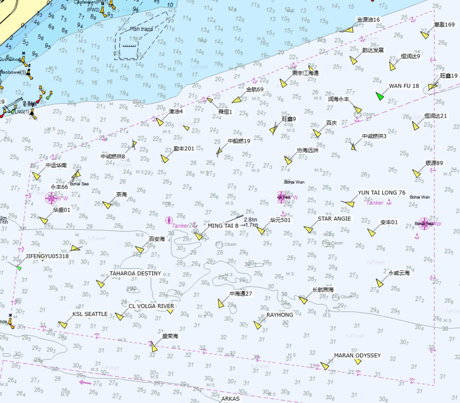
Ships need to anchor in anchorage waters for quarantine, waiting for berths, tide waiting (Yin et al., 2023), unloading at anchorage, or sheltering from typhoons. Anchorage areas are typically densely populated, with ships varying in size and type, as illustrated in Figure 1. Navigating vessels are typically needed to avoid these waters to prevent collisions. The application of intelligent ships is becoming increasingly common (Zhou et al., 2024). For example, USVs could decrease the risk of collisions for tasks such as maritime monitoring and transporting materials in complex navigation environments. USVs are autonomous surface vessels capable of navigating without onboard personnel (Specht et al., 2017). Generally, USV is smaller in size and do not require human operation, which can significantly enhance safety when navigating through anchorage areas, improve operational efficiency, and reduce labor costs. USVs can keep an eye on the marine environment and the status of anchored vessels in real time, which effectively boosts the efficiency of safety management (Wang et al., 2023). Also, USVs can effectively carry materials in a range of weather and sea conditions, which makes them especially fit for high-risk environments or those not suitable for human operations (Bae and Hong, 2023).
The core task of path planning is to design a collision-free route on a map from the starting point to the endpoint (Yin and Wang, 2021). Path planning is crucial in the navigation systems of USVs (Liu and Bucknall, 2015). It involves devising the optimal route for USVs from a starting point to a destination, primarily considering navigational safety and path efficiency. The goal of path planning is to minimize navigational risks and path costs as much as possible while ensuring mission completion by the USVs (Shu et al., 2023). Currently, various path planning algorithms can be applied in different scenarios, such as the A* algorithm, Dijkstra’s algorithm, Artificial Potential Field (APF), Rapidly-Exploring Random Tree (RRT), Genetic Algorithm (GA), and Particle Swarm Optimization (PSO).
The Dijkstra algorithm is a traditional shortest path search algorithm (Dijkstra, 1959). This algorithm identifies the shortest route from an origin to a destination, and finding paths using it is quite simple (Cover and Hart, 1967). Dijkstra’s algorithm, however, computes all nodes during path searches, which leads to poor efficiency. Improving computational efficiency involves the selection of the nearest nodes and the exclusion of unnecessary ones (Julius Fusic et al., 2018), which greatly reduces computational load and speeds up the path planning process. The optimal path can be found by calculating the number of turns and travel time through the introduction of a travel time calculation function and in complicated environments, the best route may still not be achievable (Qing et al., 2017).
The A* algorithm, as a heuristic search algorithm (Sang et al., 2021), finds the shortest path between two points. It evaluates the cost from the current node to the target using a heuristic function and expands the most promising nodes. A poorly designed heuristic function can adversely affect the smoothness and continuity of the path (Julius Fusic et al., 2018). Traditional A* can only generate piecewise linear paths, which often results in unsmooth trajectories (Dolgov et al., 2010). Dynamic simplification of the A* algorithm can reduce computation time (Lima et al., 2019). However, the adaptability of the algorithm is insufficient; especially in different scenarios, multiple adjustments of algorithm parameters are required to adapt to changing environments. To obtain safer paths, methods incorporating safe distance maintenance and heuristic function optimization were introduced (Singh et al., 2018). However, manual adjustment of safe distance parameters is required in different scenarios. Additionally, three path smoothing techniques were integrated into the A* algorithm (Song et al., 2019), generating smoother paths with fewer turns. However, the smoothing effect of this algorithm depends on parameter selection and lacks adaptability to different environments.
The basic idea of the APF method is to construct repulsive potential fields around obstacles and an attractive potential field at the target point. The attraction pulls the USVs toward the target, while the repulsion pushes the USVs away from obstacles. This method has a simple computational principle and fast operation speed but easily falls into local optima (Peng et al., 2024). Incorporating Genetic Algorithms into the APF method can effectively alleviate local minima and oscillation problems (Pan et al., 2022). However, the generated paths exhibit frequent turns, and parameter tuning becomes complex, with the design of the fitness function depending on the task scenario. Introducing the temperature parameters of a deterministic annealing strategy into the APF method (Wu et al., 2023) allows the system to increase the temperature when trapped in local minima to escape them. However, this method relies on the initial setting of temperature parameters and cooling rate; improper settings may lead to excessively long paths or failure in obstacle avoidance.Combining Model Predictive Control (MPC) with the APF forms the Model Predictive Artificial Potential Field (MPAPF) method (He et al., 2023). This approach considers the vessel’s kinematic constraints and incorporates the International Regulations for Preventing Collisions at Sea (COLREGs), effectively solving the local optimum problem of the traditional APF. However, the path changes direction frequently, affecting the vessel’s operational stability.
The RRT is a sampling-based path planning algorithm proposed by LaValle in 1998 (LaValle, 1998). This algorithm takes the starting point as the root node and performs searches in the space using random sampling, continuously adding leaf nodes to form a random tree until it reaches the endpoint. Although this algorithm is highly effective, the process of randomly generating nodes consumes a significant amount of time, and the resulting path is not smooth. By integrating AIS information and Douglas-Peucker (DP) compression to improve the traditional RRT algorithm (Gu et al., 2023), the convergence speed is increased, redundant turning points are reduced, and path smoothness is optimized. However, performance may be limited in areas with insufficient AIS data. By combining Voronoi diagrams to improve the Artificial Potential Field (APF) method (Chi et al., 2022), it guides the sampling of RRT, solves the local optimum problem, and enhances efficiency. However, in environments with fewer obstacles, the path may become longer due to detours. The improved heuristic bidirectional RRT algorithm (Zhang et al., 2022) uses a heuristic biased sampling strategy to reduce ineffective random sampling and increase convergence speed. It also reduces unnecessary turning points through path reorganization. However, in uncertain environments, inaccurate heuristic information may cause the path planning to deviate from the optimal route.
The GA is a bioinspired algorithm for optimisation that identifies the best solution to a problem by mimicking biological processes such as natural selection, inheritance, crossover, and mutation but can act as a general search technique to address path planning problems (Niu et al., 2022). The Genetic Algorithm, however, results in a high computational load, a slow convergence speed, and a tendency to fall into local optima. The addition of a new genetic mutation operator to the GA (Qu et al., 2013) can successfully stop the algorithm from reaching local optima and boost its convergence speed. The GA still raises computational complexity when dealing with extensive data and thus the combination of Voronoi diagrams with the GA (Niu et al., 2020) can markedly reduce the number of redundant nodes in the path, which helps to lower energy consumption and improve path smoothness. However, the algorithm is sensitive to parameter selection. Path planning can be considered a multi-objective optimization problem. By introducing different fitness functions for various objectives (Cheng et al., 2020), the feasibility of the path is ensured, and optimization is performed in terms of time, smoothness, and safety. However, its generality in different environments requires further verification. Using a heuristic median insertion method to generate a high-quality initial population (Li et al., 2021) and optimizing the Genetic Algorithm through multi-objective fitness functions (path length, safety, energy consumption) improved the convergence speed and shortened the path length. However, this method did not perform detailed optimizations on path smoothness.
The PSO (Kennedy and Eberhart, 1995) is another biologically inspired algorithm. It was originally designed to simulate the movement of particles in a solution space, iteratively updating their positions and velocities to search for the optimal solution to a function. The AquaFeL-PSO algorithm (Jara Ten Kathen et al., 2024), which integrates multimodal PSO, Gaussian Processes (GP), and Federated Learning (FL), reduces the likelihood of getting trapped in local optima, while improving both convergence speed and algorithm robustness. However, the Gaussian Process modeling may lead to high computational complexity. Traditional PSO-based path planning algorithms typically assume a static environment, making them less effective in complex dynamic scenarios. To address this limitation, the OkayPlan algorithm (Xin et al., 2024) combines dynamic obstacle motion modeling, Dynamic Priority Initialization (DPI), and a relaxation strategy, significantly enhancing both the safety and real-time performance of path planning. However, the conservative planning strategy of OkayPlan may compromise the optimality of path length. ACO-based path planning, through parameter optimization and adjustment of its search strategies (Heng et al., 2024), can identify the shortest obstacle-free path while ensuring safety. However, in complex environments, ACO is prone to falling into local optima, failing to achieve a truly global optimal path.
In anchorage areas, the high density of anchored vessels complicates traditional path planning, making it difficult to guarantee both safety and efficiency. The close proximity between vessels increases the collision risk for USVs. Therefore, an algorithm that can recognize and avoid risk areas while maintaining path efficiency is proposed. In this paper, a modified A* algorithm, named RAPO, is introduced, which incorporates risk awareness and models the risk field using a Gaussian influence function. After the path is optimized, the DPSS is applied to smooth the path, ensuring its smoothness and feasibility. The main contributions of this paper are as follows:
● The RAPO is proposed, which effectively incorporates the risk characteristics of anchorage areas, thus improving both path safety and economic efficiency.
● A Gaussian influence function is used to model the risk field in the anchorage area, addressing the limitations of the traditional A* algorithm in complex environments.
● The DPSS is applied to smooth the optimized path, ensuring its navigability and smoothness, thereby enhancing its applicability in real-world scenarios.
2 Methodology
2.1 Traditional A* algorithm
The A* algorithm is one of the most widely used methods in path planning. The basic idea involves define the starting point S as the parent node, to estimate the cost to the surrounding nodes n, and selecting the node with the lowest cost as the next parent node until the target node G is identified. Commonly used search directions consist of 4-connected and 8-connected grid searches. The 4-connected mode considers only horizontal and vertical movements, whereas the 8-connected mode additionally accounts for diagonal movements. Due to the complex movement characteristics of USVs in anchorage areas, this paper uses an 8-connected grid search to support more flexible and efficient navigation and thus the node evaluation function consists of two components, as shown in Equation 1:
where f(n) is the total cost of the current node, g(n) represents the minimum path cost from the starting point S to the current node n and h(n) represents the estimated minimum cost from the current node n to the target node G.
The traditional A* algorithm typically uses heuristic functions such as the Euclidean distance and the Manhattan distance. This paper employs the Euclidean distance, which calculates the straight-line distance between two points to provide an accurate estimation of the path cost. The direct use of the straight-line distance between two points allows for the estimation of movement cost in path planning. Thus the Euclidean distance in the A* algorithm effectively directs the search process to favour paths that are physically nearer to the target, thereby improving search efficiency and reducing computational costs. The heuristic function h(n) is shown in Equation 2, the actual cost g(n) is shown in Equation 3, and the path cost is shown in Equation 4:
where xn is the x-coordinate of any node n, yn is the y-coordinate of node n, xG is the x-coordinate of the target node G, yG is the y-coordinate of the target node G, and i is the index of the nodes in the path.
2.2 Risk-aware path optimisation algorithm
The RAPO algorithm was proposed to improve the safety and efficiency of USVs navigation through anchorage areas. The RAPO integrates risk assessment with a dual-phase smoothing strategy. Risk assessment guides the A* algorithm to avoid high-risk areas by evaluating each grid based on a ship domain model and Gaussian influence function. The DPSS smooths the path in two phases. First, Bresenham’s algorithm is used to reduce the number of sharp turns. Second, cubic B-spline path smoothing is applied to enhance path continuity.
2.2.1 Risk assessment
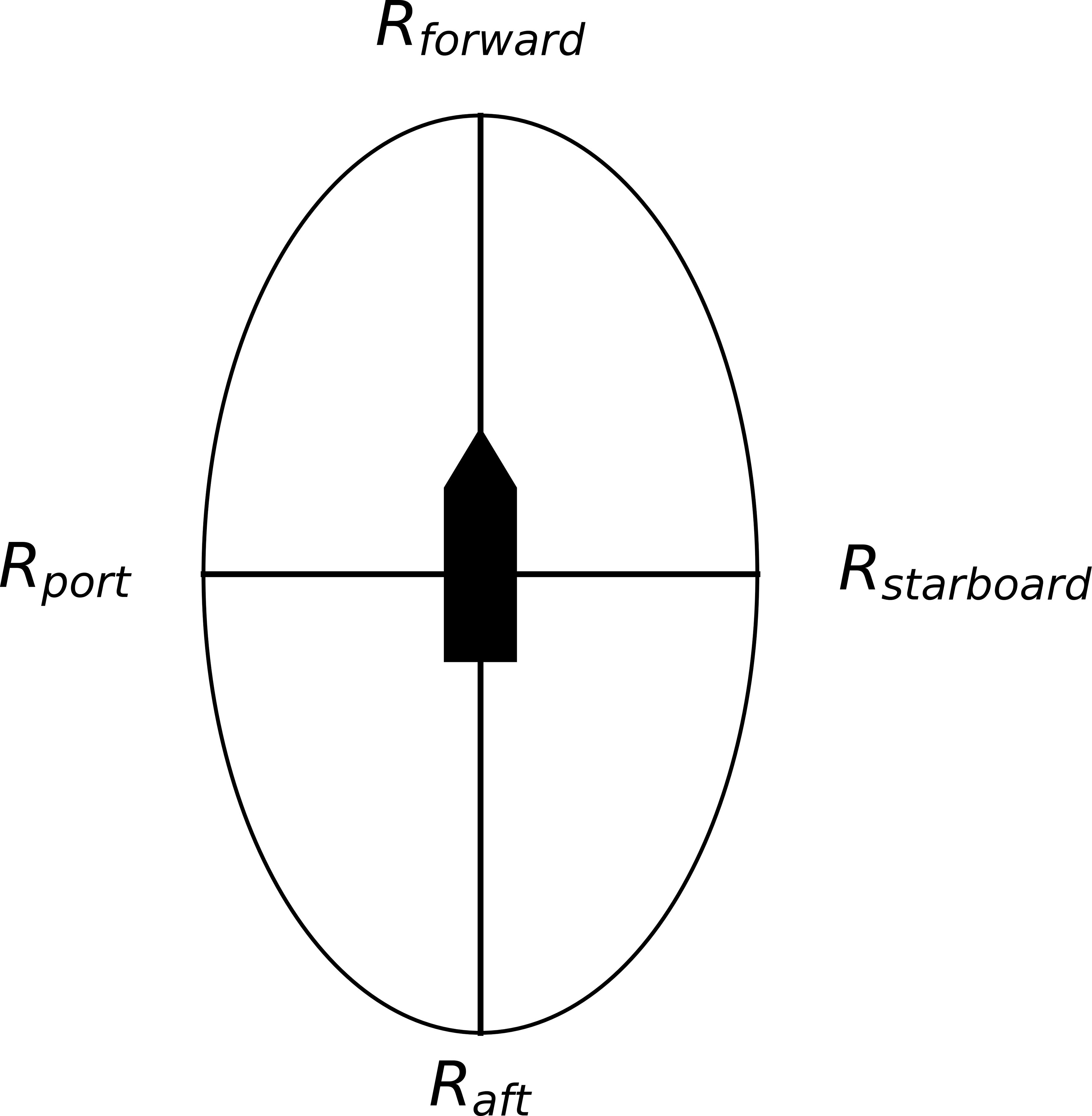
The ship domain (Pietrzykowski and Uriasz, 2009) is a concept used to represent the safe area around a vessel. It is typically defined as a two-dimensional area surrounding the vessel, which other ships should avoid to prevent collisions. The size and shape of this domain can vary on the basis of the vessel’s size, speed, and navigational environment. The ship domain is usually quantified by boundary radii in four directions around the vessel: forwards (bow), aft (stern), left (port side), and right (starboard side), expressed in multiples of the ship’s length (L). The establishment of an unnavigable zone around a ship prevents collision accidents. A typical ship domain representation is illustrated in Figure 2, where the boundary radii in each direction are used to depict the safe zones around the vessel in different orientations.
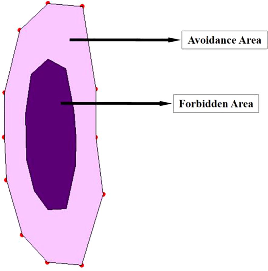
A reasonable establishment of unnavigable zones can significantly reduce collision risk, improve navigation efficiency, and enhance overall safety (Goerlandt and Kujala, 2014). A dodecagonal forbidden zone model (Kundakçı et al., 2023), which closely approximates an elliptical shape, was proposed by Kundakçı et al. As shown in Figure 3, the dark purple area represents the forbidden zone. In this paper, an elliptical shape was directly adopted for the forbidden zone. Using an elliptical shape for the unnavigable zone around the anchored ship has significant advantages. The long axis of the elliptical unnavigable zone aligns with the longitudinal axis of the ship, providing greater fore-and-aft safety distance. The short axis provides the lateral safety distance, preventing other ships from approaching the sides of the anchored ship and reducing the collision risk. In this paper, elliptical unnavigable zones were set up on the basis of the captain’s navigational experience. If the ship’s length is L, then the semimajor axis would be 1.2L; if the ship’s width is W, then the semiminor axis would be 2W. The risk value for grids within the unnavigable zones is set to infinity.
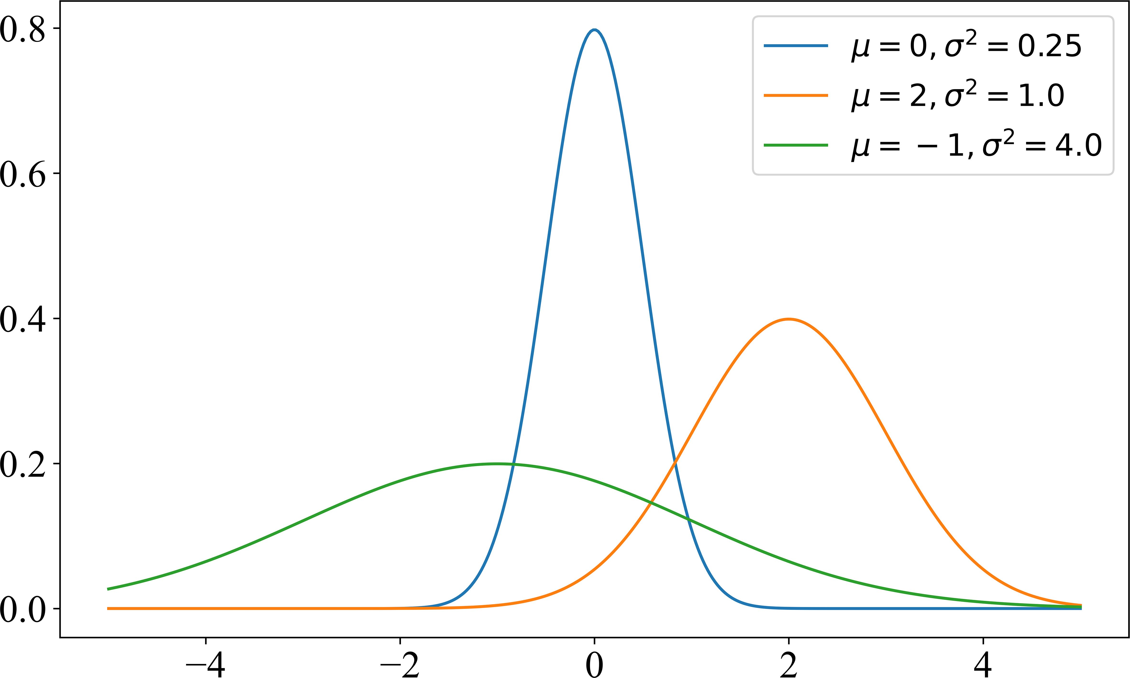
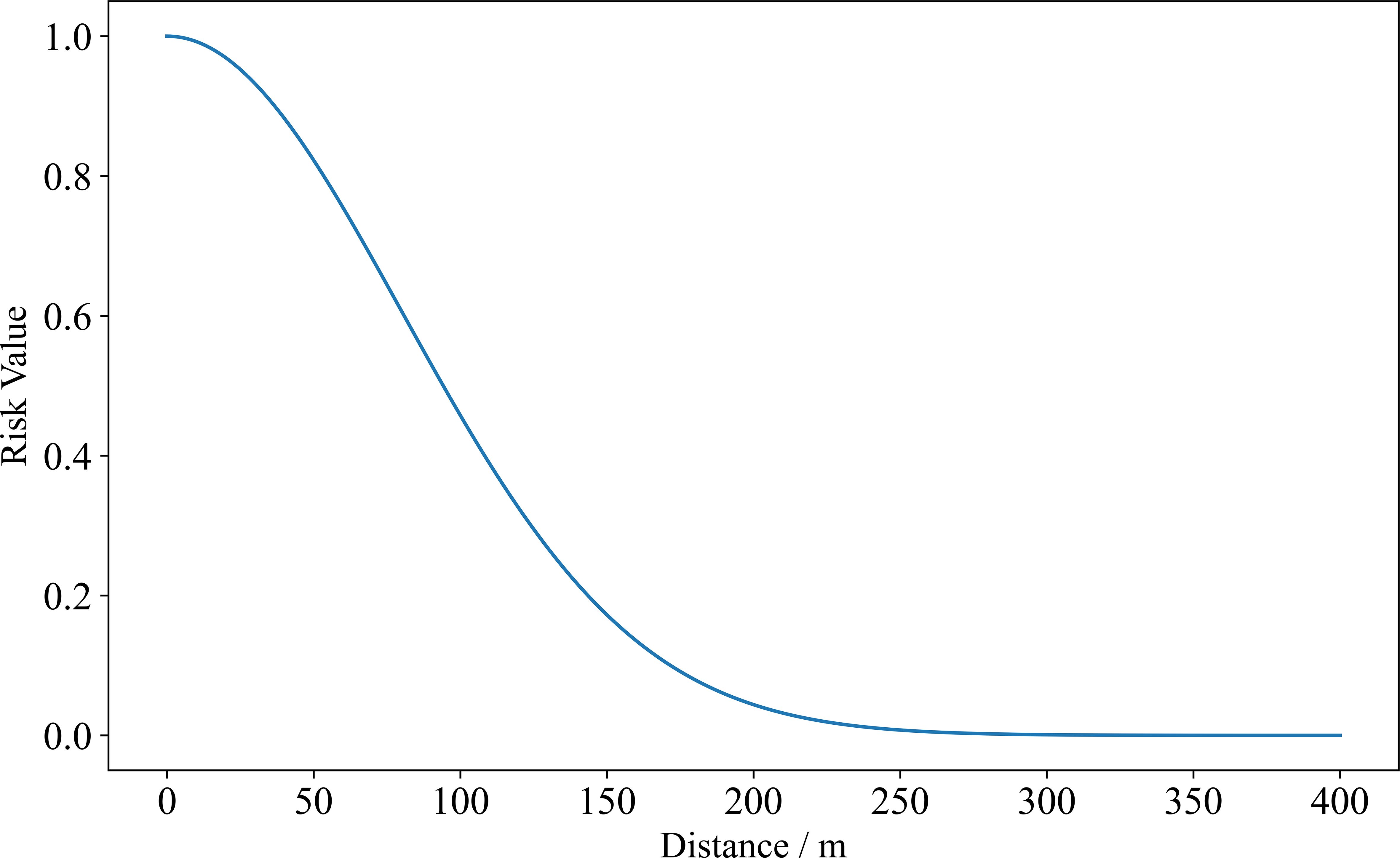
When a USV navigates through an anchorage area, the anchored ships pose a certain risk to the USV. This risk can be characterised by the Gaussian function (Liu and Ma, 2023). The Gaussian function was introduced by the German mathematician Carl Friedrich Gauss. It was first introduced in his work in the early 19th century and has been widely applied in probability theory and statistics, especially in normal distributions. The normal distribution is one of the most important distributions in statistics and describes the distributions of many natural phenomena and experimental data. The standard form of the Gaussian function is shown in Equation 5, and the graph of the Gaussian function is shown in Figure 4:
In Equation 5, μ is the mean, indicating the central position of the Gaussian distribution. It is the symmetric centre of the Gaussian curve, determining its position and controlling the peak position of the curve, which reaches its maximum at x = μ. The σ is the standard deviation, representing the width of the Gaussian distribution, which determines the degree of data dispersion: the larger the standard deviation is, the wider and flatter the curve; the smaller the standard deviation is, the narrower and steeper the curve. In statistics, the normal distribution has an important property known as the three-sigma rule (68-95-99.7 rule), which states that in a normal distribution, approximately 68.27% of the data lie within one standard deviation of the mean [μ − σ, μ + σ], approximately 95.45% of the data lies within two standard deviations [μ − 2σ, μ + 2σ], and approximately 99.73% of the data lies within three standard deviations [μ − 3σ, μ + 3σ].
The Gaussian influence function is a variant of the Gaussian function and is used mainly to describe the exponential influence of a quantity with distance or time. Its form is shown in Equation 6. The three-sigma rule of the Gaussian function also applies to the Gaussian influence function. In the Gaussian influence function, the values range from (0, 1), which aligns with the typical range of risk values.
The Gaussian influence function is used to describe the ship domain and assess risks (Im and Luong, 2019), this method is highly reliable and effective. In risk assessment, the Gaussian influence function represents the attenuation of risk with distance, providing an intuitive and computationally simple model for path planning and obstacle avoidance. Its smoothness and symmetry ensure continuity and uniformity in risk distribution, making it especially effective for representing the high risk near anchored ships, where risk diminishes gradually with increasing distance.
In this paper, the map is divided into Voronoi polygons. The distance from each ship to the Voronoi polygon boundary is half of the ship spacing, the risk posed by each anchored ship is confined to the area within its assigned Voronoi polygon. For example, a Gaussian influence function with a parameter of σ = 80 can be used to depict the risk values, as shown in Figure 5.
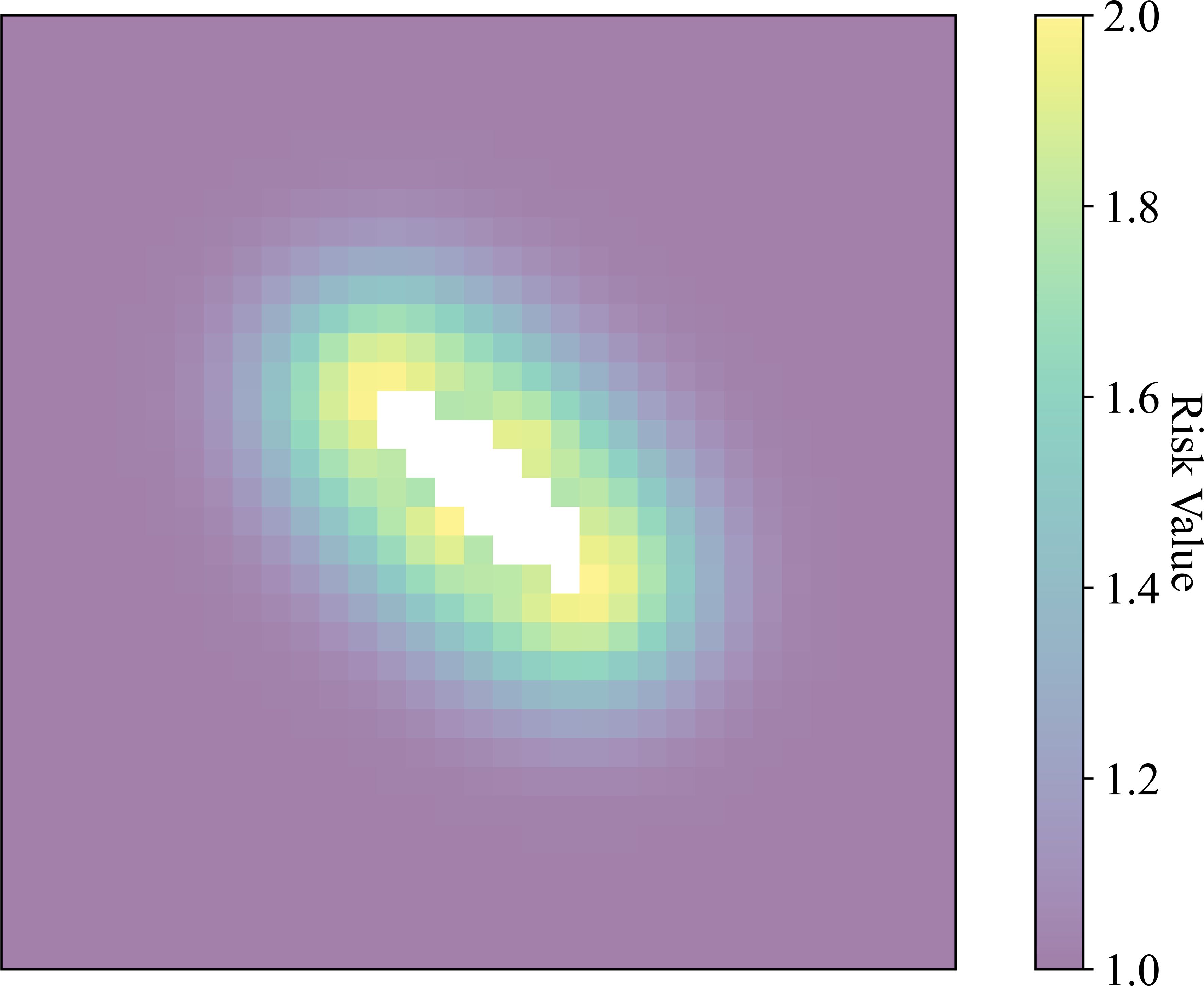
The Gaussian influence function ensures that the risk gradually decreases with distance, naturally simulating the risk posed by the anchored ship to its surroundings. By calculating the distance d from a point to the boundary of the unnavigable zone and applying the Gaussian influence function, precise risk assessments can be provided for path planning, thus enhancing navigation safety and the effectiveness of path selection. The map is converted to grids, with d being the distance from the centre of the grid to the boundary of the unnavigable zone, which is calculated as shown in Equation 7. Every grid outside the unnavigable zone has a risk value with the range set to [1,2), and the grid risk function derived from the modified Gaussian influence function is shown in Equation 8.
In Equation 7, x and y are the 2-dimensional coordinates of the grid centre, whereas xedge and yedge are the 2-dimensional coordinates of the corresponding point on the ellipse boundary.
In Equation 8, n represents the index or identifier of the current grid point, which is used to indicate its position within the overall risk matrix. D(n) is the grid risk degree function, and d represents the distance from a point to the boundary of the unnavigable zone. When d > 0, the point is outside the unnavigable zone, and the risk decreases as the distance increases. When d = 0, the point lies on the boundary, and the risk is set to infinity (∞). When d< 0, the point is inside the unnavigable zone, and the risk is also set to infinity (∞).
The risk caused by a single ship to its surroundings is displayed on the grid map, with white representing the forbidden zone, and yellow to purple indicating gradually decreasing risk levels, as shown in Figure 6.
The traditional A* algorithm uses only path length as its heuristic function, causing planned paths to often approach obstacles and fail to guide USVs to navigate safely and smoothly. To address this issue, the RAPO incorporates the ship domain and Gaussian influence function to determine the risk zones formed by anchored ships for other vessels. The risk degree function is included as part of the RAPO evaluation function for path planning.
The evaluation function is shown in Equation 9:
where f(n) is the total cost of the current node D(n) is the grid risk degree function, p(n) represents the path cost from the start point S to the current point n after including the risk, h(n) represents the estimated minimum cost from the current point n to the goal node G, xG is the x-coordinate of the target node G, and yG is the y-coordinate of the target node G.
The superiority of Equation 9 over Equation 3 lies in its better consideration of potential collision risks. By introducing the grid risk degree function D(n), USVs can effectively avoid entering unnavigable zones.
2.2.2 Dual-phase smoothing strategy
2.2.2.1 Bresenham-based path smoothing
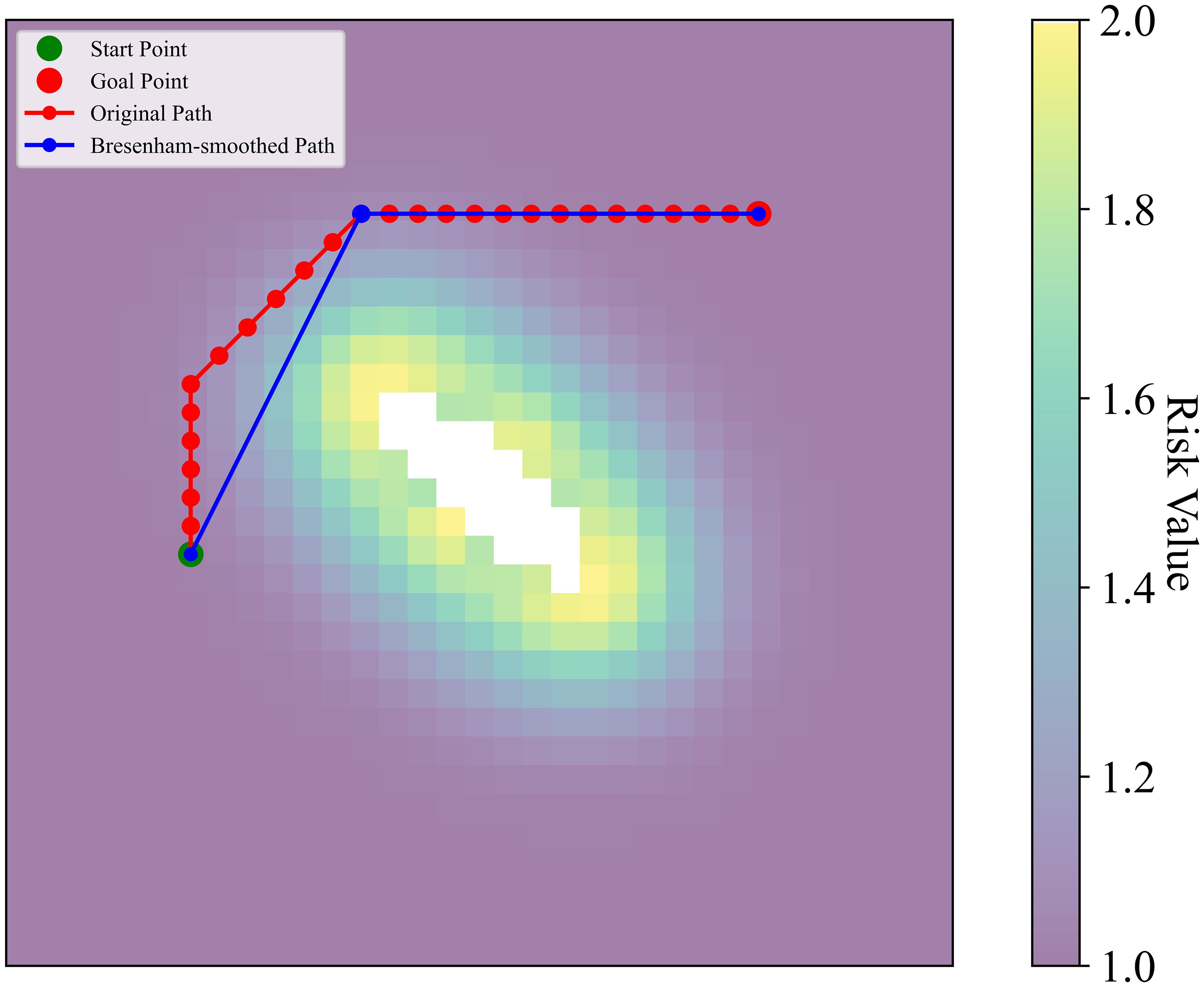
The RAPO, which incorporates risk assessment, is limited by the heuristic search principle, which does not allow cross-grid search, resulting in many redundant turning points in the planned path. Path smoothing aims to improve the continuity and feasibility of the USV path and lower the energy consumption. In practical applications, path smoothing can significantly enhance the navigation performance and task execution efficiency of USVs. By introducing a path smoothing strategy, the path length can be optimised, removing redundant nodes and unnecessary turns.
The initial path, generated by the RAPO, which incorporates risk assessment, may contain many redundant nodes and turns. To optimise this path, the Bresenham line algorithm (Wang et al., 2024) is used to check the connections between every pair of adjacent nodes, and a schematic of Bresenham line path smoothing is shown in Figure 7. If the risk values of all intermediate nodes between the current node and a distant node are within an acceptable range (below the set threshold), these nodes can be directly connected. By doing so, intermediate redundant nodes are skipped. The pseudocode for the initial smoothing is shown in Algorithm 1.
Algorithm 1. Bresenham-based path smoothing pseudocode.

2.2.2.2 Cubic B-spline-based path smoothing
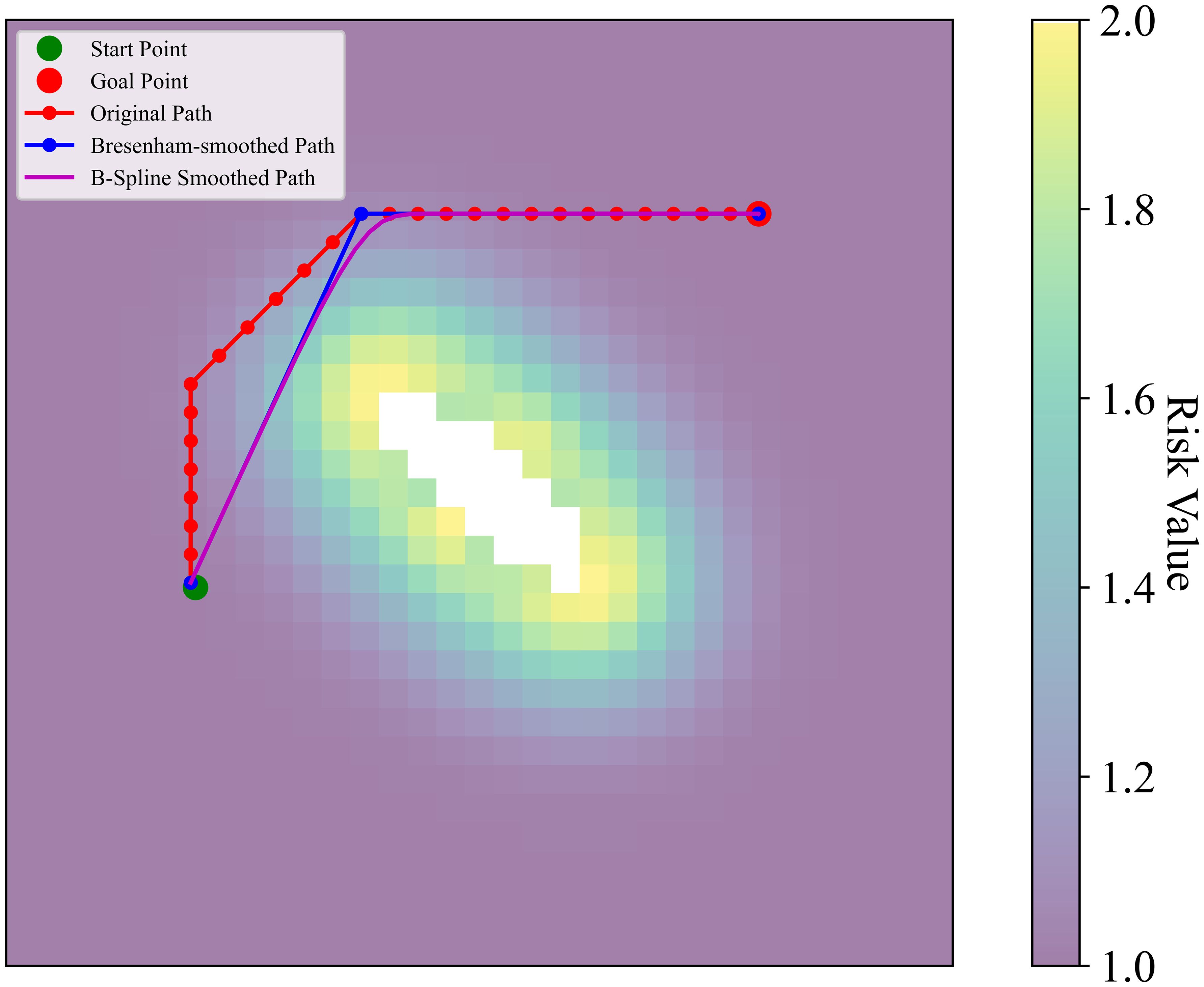
After the initial smoothing by the Bresenham algorithm, although redundant nodes and sharp turns have been partially reduced, significant angular changes may persist. These changes can lead to large turning angles, increasing energy consumption and operational difficulty for USVs during actual operation. To further optimise the smoothness and continuity of the path, a path smoothing method based on cubic B-splines (Muñoz, 2008) was introduced in the second stage of the DPSS. The mathematical definition of the B-spline curve is shown in Equation 12:
In Equation 12, represents the point on the curve at parameter u, is the ith control point, and is the B-spline basis function, with k=3 indicating a cubic B-spline.
The recursive definition of the cubic B-spline basis function is as follows:
For the zeroth-degree B-spline basis function, as shown in Equation 13:
For higher-degree B-spline basis functions, as shown in Equation 14:
To generate smooth B-spline curves, uniformly distributed knot vectors were adopted. If there are n+1 control points, the knot vectors are typically defined as:
These uniformly distributed knot vectors ensure a smooth transition between control points in the B-spline curve.
In accordance with the standards set forth in the U.S. Navy’s “Navy USV Master Plan”, USVs with lengths ranging from 3 to 11 metres are widely employed in various mission scenarios. In this paper, a typical 10-metre USV with a turning radius of approximately 30 metres was selected. The 30-meter insertion interval not only meets the requirements for path smoothing but also aligns with the maneuvering characteristics of the USV, ensuring that the generated path is both operationally stable and feasible. Consequently, control points were inserted every 30 metres. A schematic of the second smoothing is shown in Figure 8. The pseudocode for the second path smoothing is shown in Algorithm 2.
Algorithm 2. B-Spline-based path smoothing pseudocode.
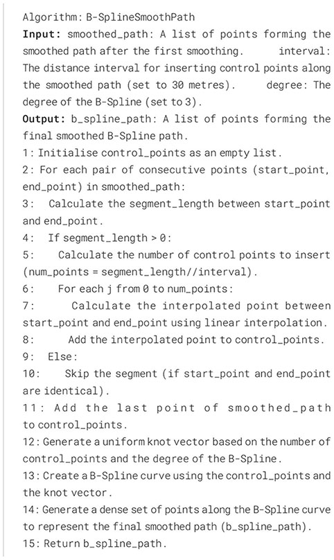
The cubic B-spline method significantly improved path smoothness, reduced the number of sharp turns, enhanced the navigational stability of the USV, and optimised the path’s continuity and length. As a result, the economic efficiency and safety of the generated path in complex environments were effectively improved.
3 Simulation experiments
3.1 Experimental environment setup
All simulations were conducted on a computer with Microsoft Windows 11 as the operating system, an Intel i5 3.10 GHz twelve-core CPU, and 16 GB of RAM. To validate the rationality and efficiency of the RAPO algorithm proposed in this paper, simulations were carried out on a 2D static grid map with PyCharm as the development environment.
3.2 Anchorage area model construction
3.2.1 Ship positioning and Voronoi polygon partitioning
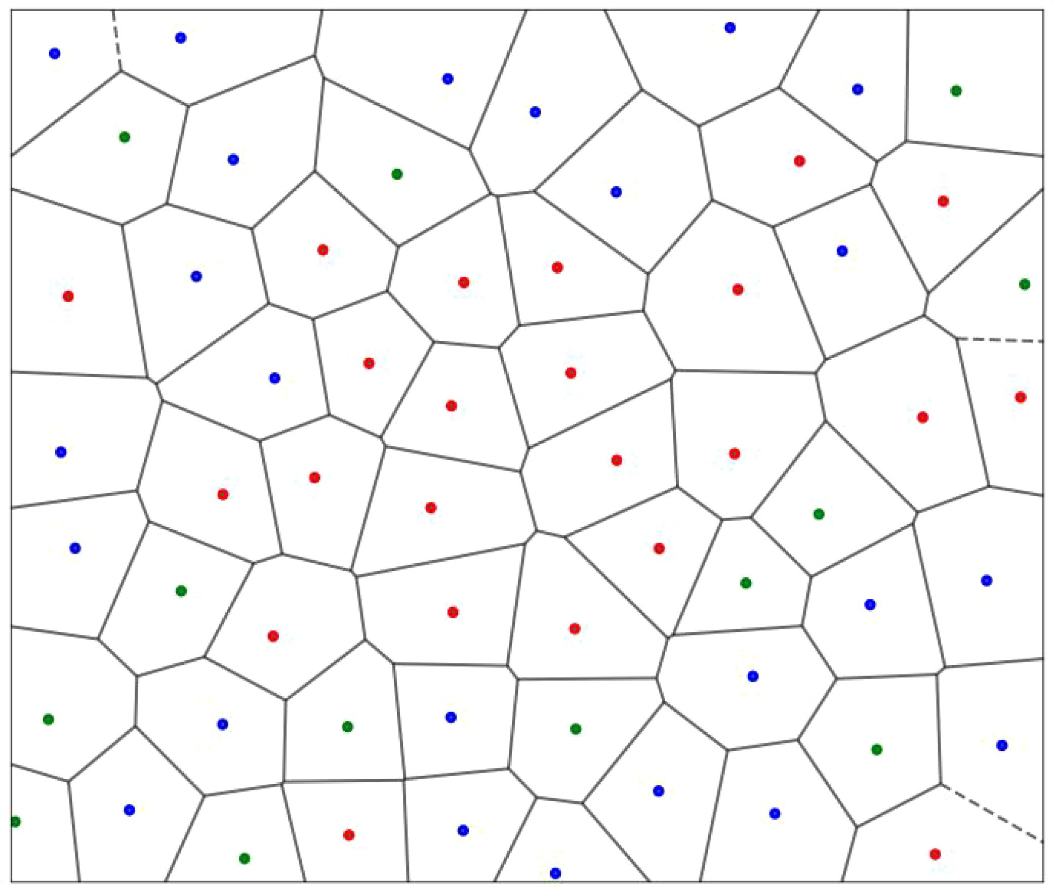
In this paper, anchorages and anchored ships in Beibu Gulf waters were referred to. The simulated anchorage size was set to 5.5 km × 4.8 km. Sixty anchored ships, each with lengths ranging from 90 to 150 m, were included. The distance between ships was set to 500 to 750 metres. The heading of each ship was uniformly distributed within the range of 135° to 165°. The coordinates of the anchored ships were set to determine their positions. Thirteen ships with lengths of 90 to 110 m are represented by green dots. Twenty-four ships with lengths of 110 to 130 m are represented by blue dots. Twenty-three ships with lengths of 130 to 150 m are represented by red dots. The anchored ships were used as points Pi to partition the anchorage area via the Voronoi polygon. This process prepares for the introduction of risk from the anchored ships. With Voronoi polygon partitioning, the distribution of the simulated ships in the defined anchorage area is shown in Figure 9.
3.2.2 Grid-based processing and risk evaluation
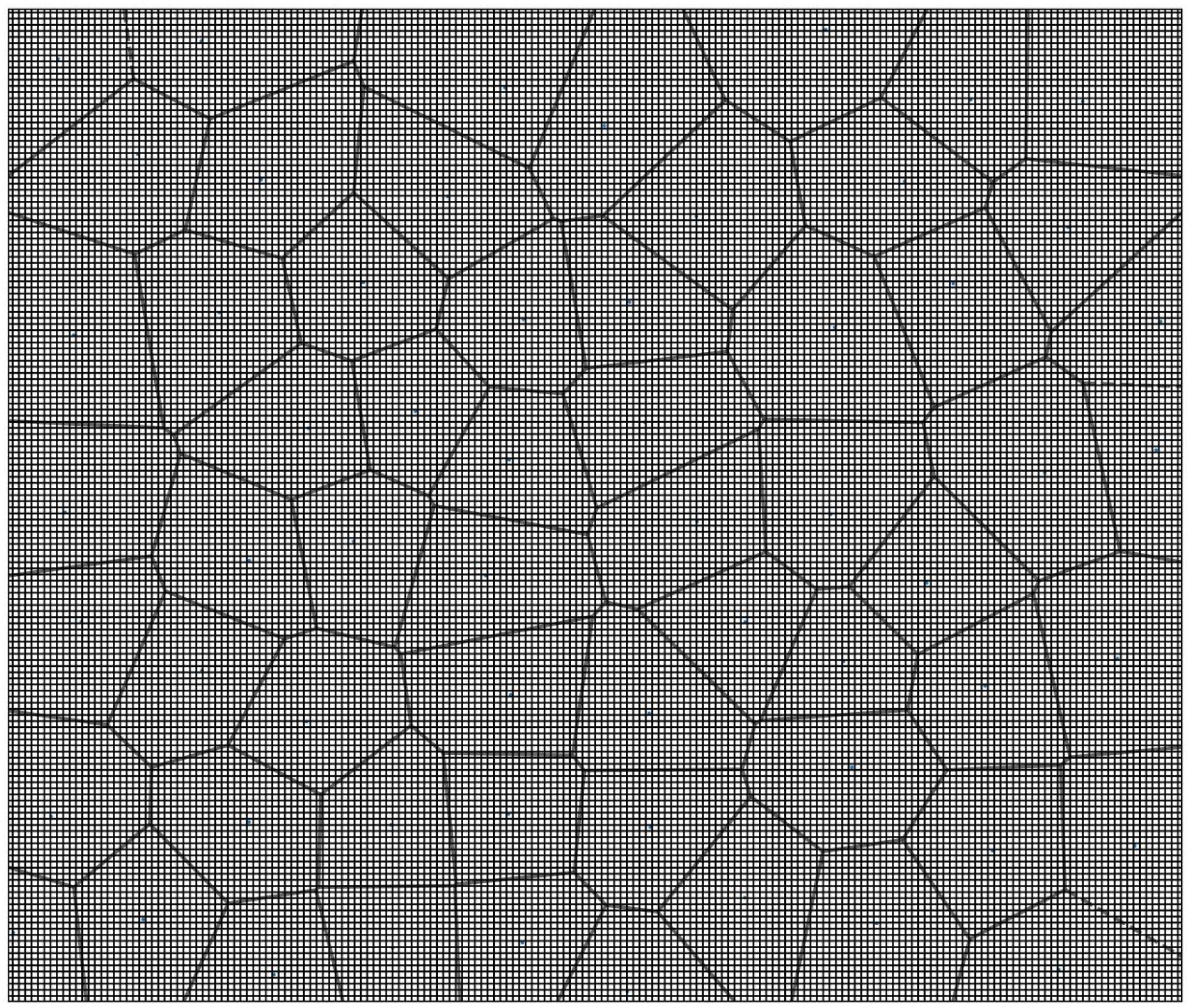
When processing environmental maps, grid-based maps are the most commonly used form of representation and processing, as they effectively convey spatial information and support the application of various algorithms. The grid size was set to 30 m × 30 m, considering that the normal length of a USV is approximately 10 m. The resulting grid map used in the risk assessment is shown in Figure 10.
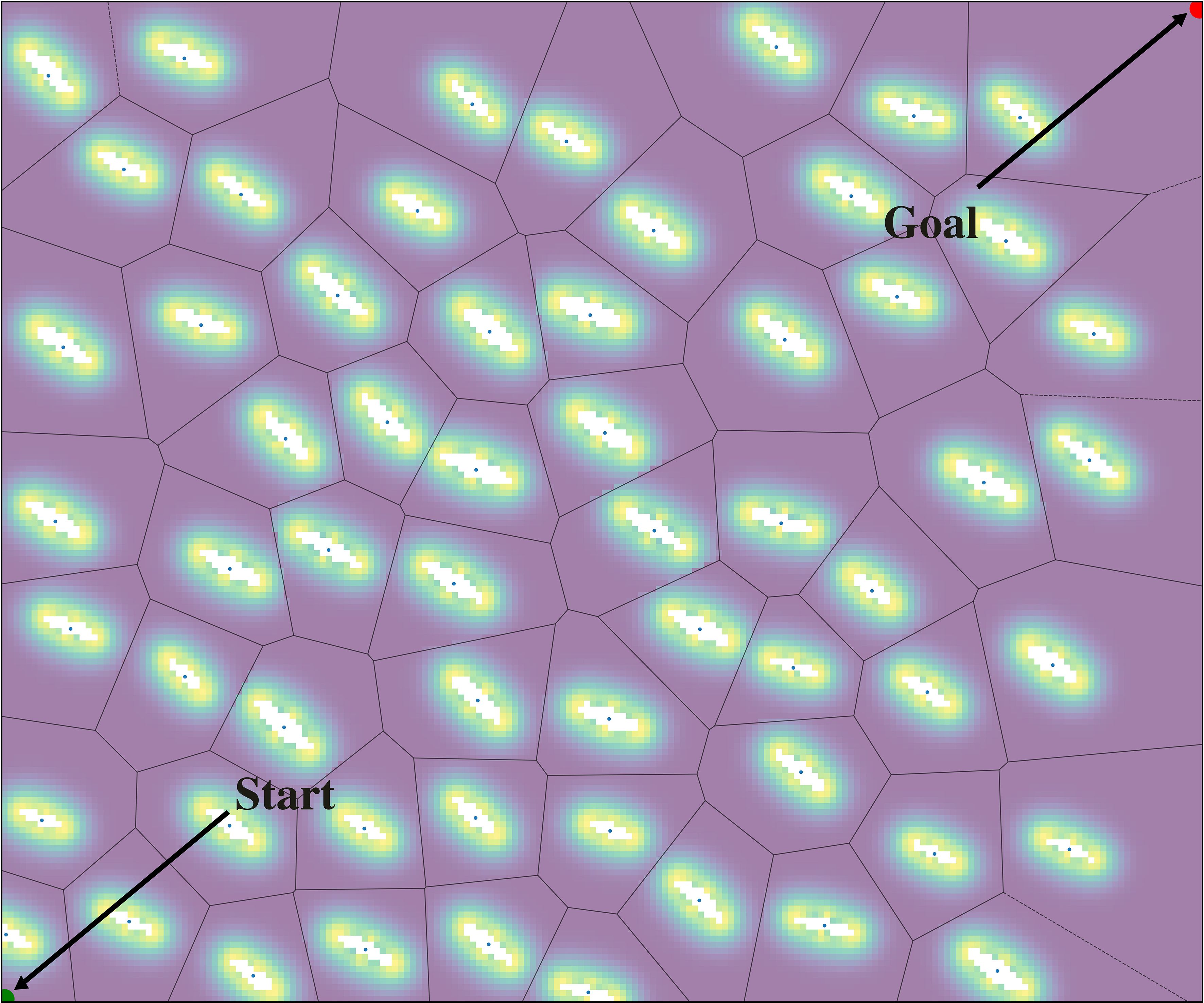
Before the simulation experiments, risk values were assigned to each grid on the basis of the Gaussian influence function. Each anchored ship formed a risk area. The anchored ships were used as seed points for the Voronoi polygons. Each polygon was a risk assessment unit. It was assumed that each anchored ship affected only the navigable waters within its corresponding Voronoi polygon. The distance between anchored ships ranges from 500 to 750 m, and the shortest distance from an anchored ship to the boundary of its Voronoi polygon is approximately 250 m. Considering that the main influence range of the Gaussian distribution is concentrated within [−3σ,+3σ], corresponding to an actual risk range of 250 m, 3σ =250 is set, yielding σ ≈ 80. So, the parameter σ in the Gaussian influence function was set to 80.
After the map was converted to grids, each grid was assigned a risk value. The risk value for unnavigable zones was set to infinity. Grids in this area are displayed in white. The risk values for risk zones ranged from 1 to 2, with colours representing the risk value from purple (low risk) to yellow (high risk), transitioning through cyan and green. A risk distribution map of anchored ships is shown in Figure 11, where “Start” is the starting point and “Goal” is the ending point.
3.3 Path planning and smoothing
The RAPO algorithm was used to plan safe and efficient paths for USVs in anchorage areas. First, a modified Gaussian influence function was used to conduct risk assessments to minimize potential risks. Then, the algorithm optimises the path through two stages of DPSS path smoothing. In the first phase, a Bresenham-based path smoothing method is employed to eliminate unnecessary turns and redundant nodes in the initial path. In the second phase, a cubic B-spline-based path smoothing method is used to further smooth the path obtained from the first phase, inserting a control point every 30 meters on the path obtained from the first-phase smoothing, and then applying a cubic B-spline curve to smooth the path. After the DPSS, the number of turns is significantly reduced, and the smoothness of the path is improved.
3.4 Simulation results
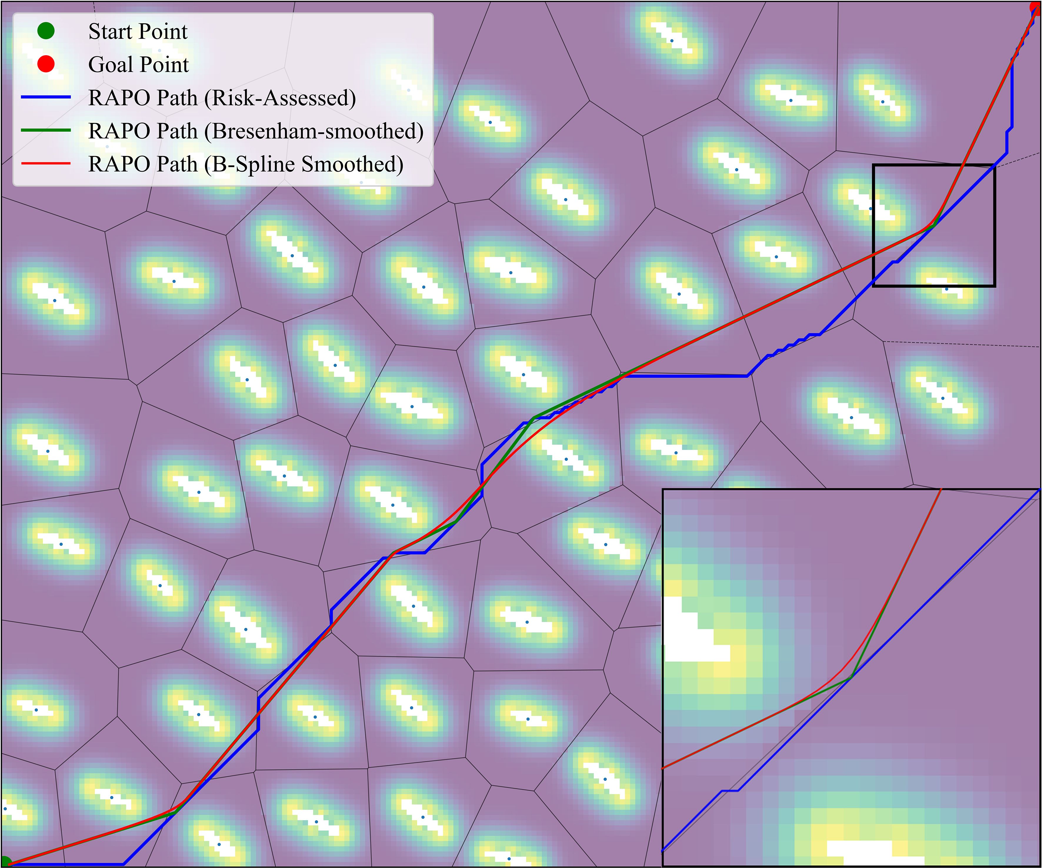
The RAPO algorithm integrates risk assessment and the DPSS, to verify that the RAPO algorithm can be applied to path planning in anchorage areas, simulation experiments were conducted. The path planning results of the RAPO algorithm at a path risk value of 1.5 are shown in Figure 12, where the blue solid line represents the initial path from the risk-improved A* algorithm within RAPO, the black solid line indicates the path after the first-phase smoothing based on Bresenham’s algorithm, and the red solid line shows the final path after the second-phase smoothing using a cubic B-spline.
The path planning results indicate that the RAPO algorithm, which includes DPSS, significantly improves both path length and the number of turns across different path risk tolerances. Table 1 presents the path lengths, number of turns, and maximum turning angles for the RAPO algorithm under path risk tolerances of 1.2, 1.5, and 1.8. Compared with the original paths generated through risk assessment within the RAPO algorithm, the lengths of the smoothed paths were reduced by 7.13%, 7.60%, and 7.70%, respectively. The number of turns decreased by 81.13%, 90.57%, and 94.34%, respectively, while the maximum turning angle was reduced by 17.78%, 13.33%, and 11.11%, respectively. When comparing the smoothed paths at different risk tolerances, the path length with a risk tolerance of 1.5 was reduced by 4.9%, and the number of turns decreased by 57.14% compared with the smoothed path with a risk tolerance of 1.2. The path length at a risk tolerance of 1.8 is reduced by 0.51% compared to that at a risk tolerance of 1.5, and the number of turns decreases by 50%. The path length at a risk tolerance of 1.8 is reduced by 0.61% compared to that at a risk tolerance of 1.2, and the number of turns decreases by 70%. As the risk tolerance increases, the resulting path length continuously shortens, and the number of turns decreases, thereby reducing the operational difficulty and energy consumption of the USV, thus ensuring the economy of the path.
4 Discussions
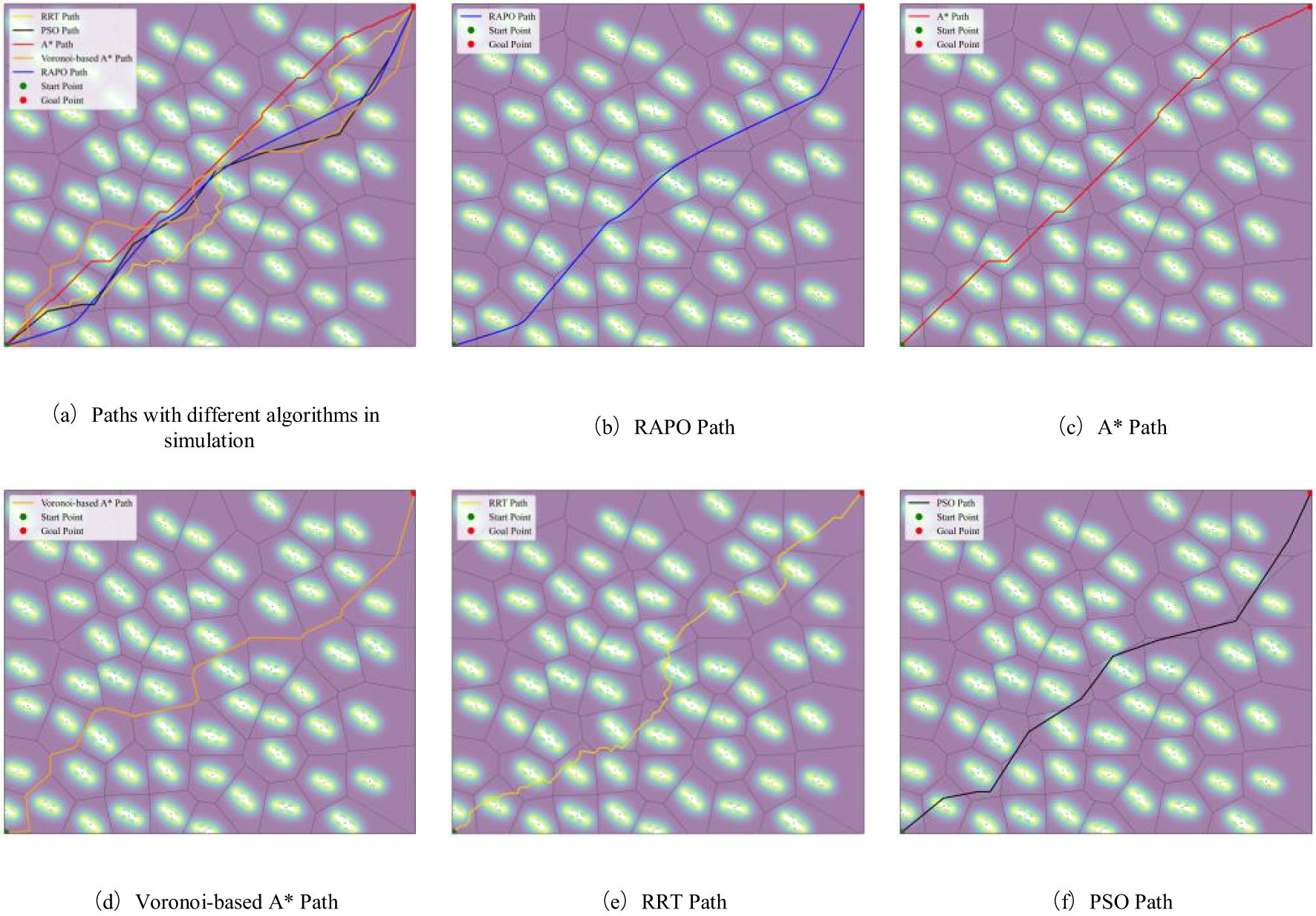
The RAPO algorithm proposed in this paper first assesses the risk of anchored ships and then plans a route, while also smoothing the route to ensure a safe and economical path for USVs in anchorage areas. The results from simulation experiments demonstrate that the RAPO algorithm outperforms the A* algorithm (Hart et al., 1968), the Voronoi-based A* algorithm (Fedorenko and Gurenko, 2016), RRT algorithm (LaValle, 1998) and PSO algorithm (Kennedy and Eberhart, 1995) in terms of path length, the number of turns as well as a path smoothness.
Figure 13 illustrates the paths obtained by the five algorithms. The blue solid line represents the path generated by the RAPO algorithm, the red solid line represents the path produced by the traditional A* algorithm, the orange solid line shows the path from the Voronoi-based A* algorithm, the golden yellow solid line represents the path obtained by the RRT algorithm, and the black solid line represents the path from the PSO algorithm.
When the risk tolerance is 1.5, path planning was conducted using five different algorithms, and the simulation results are shown in Table 2. In terms of path length, the RAPO algorithm resulted in a path length of 7.984 km, which is significantly shorter than the paths obtained by the other four algorithms. It can be seen that while considering risk factors to ensure path safety, its path length is also the shortest, and the overall path length was further optimized after applying the DPSS. Regarding the number of turns, the path obtained by the RAPO algorithm has only 5 turns, which is significantly fewer than the 39 turns of the traditional A* algorithm, the 20 turns of the Voronoi-based A* algorithm, the 68 turns of the RRT algorithm, and the 7 turns of the PSO algorithm. In terms of the maximum turning angle, the path generated by the RAPO algorithm has a maximum turn of only 40°, which is significantly lower than the 45° of the traditional A* algorithm, the 90° of the Voronoi-based A* algorithm, the 128° of the RRT algorithm, and the 57° of the PSO algorithm. It can be seen that the path smoothing phase in the RAPO algorithm effectively reduces unnecessary turns, enhances path smoothness, and decreases the operational difficulty and energy consumption of USVs. Additionally, the maximum risk value of the path obtained by the RAPO algorithm is 1.484, which, although higher than that of the path obtained by the Voronoi-based A* algorithm, is still within the set range. Therefore, the RAPO algorithm can plan a safe path for USVs in anchorage areas.
The traditional A* algorithm focuses solely on finding the shortest path, without considering path safety, resulting in poor overall path safety. Additionally, the traditional A* algorithm generates paths with numerous redundant turns, which increases operational complexity and energy consumption. Although the Voronoi-based A* algorithm considers path safety, it does not optimize path length, resulting in longer paths. Furthermore, the paths are constrained by the boundaries of Voronoi polygons, leading to more sharp turns, which further increases operational difficulty and energy consumption. The RRT algorithm lacks path smoothness in path planning, generating longer paths with excessive sharp turns and limited overall optimization capability. Although the PSO algorithm demonstrates certain global optimization capabilities, its generated paths perform poorly in risk avoidance, making it difficult to ensure path safety.
The RAPO algorithm mainly combines risk assessment with the DPSS. The addition of risk assessment to path planning allows the path to successfully bypass high-risk areas. The DPSS process eliminates a large quantity of unneeded turns and improves the flow of the path. The RAPO algorithm is capable of designing routes for USVs in challenging environments, ensuring both the safety and economy of the path, and also making USVs operations less difficult and less energy intensive.
5 Conclusions
This paper proposes the RAPO algorithm to enhance the safety and efficiency of USVs in anchorage areas. The algorithm integrates a grid-based risk function derived from the ship domain model, a Gaussian influence function, and the DPSS. By defining prohibited zones using the ship domain and conducting risk assessments on waters outside these zones with the Gaussian influence function, the algorithm effectively avoids high-risk areas, improving the safety of path planning. Furthermore, the DPSS reduces the number of turns, resulting in a smoother and more efficient planned path.
Still, the algorithm has some inherent limitations. Initially, the algorithm’s computational burden is quite high, which leads to an increase in time needed and the smoothing results are contingent upon the parameter settings. Then, the algorithm is currently mostly focused on static environments, which may influence its use in real complex marine settings.
In future research, the role of ocean currents in the navigation environment will be examined to better understand USVs navigation in anchorage areas. In addition, the exploration of path planning for USVs in dynamic environments with both static and dynamic obstacles will be undertaken to further improve the practicality of the RAPO algorithm, allowing it to perform well in static environments and to provide safe and effective path planning in complex dynamic settings.
Data availability statement
The raw data supporting the conclusions of this article will be made available by the authors, without undue reservation.
Author contributions
HW: Formal analysis, Methodology, Validation, Writing – original draft, Writing – review & editing. SM: Conceptualization, Methodology, Software, Validation, Writing – original draft, Writing – review & editing. XM: Writing – original draft. JZ: Writing – original draft. RL: Writing – original draft.
Funding
The author(s) declare financial support was received for the research, authorship, and/or publication of this article. This research was funded by the National Natural Science Foundation of China (51479157, 52171346), China Scholarship Council Program (202208440272), Hubei Key Laboratory of Inland Shipping Technology (NHHY2020002), the Special Projects of Key Fields of Universities in Guangdong Province (2023ZDZX3003) and Teaching Quality and Teaching Reform Project of Guangdong Undergraduate Colleges and Universities (010201132401).
Acknowledgments
Special thanks go to the funding support provided for this research.
Conflict of interest
The authors declare that the research was conducted in the absence of any commercial or financial relationships that could be construed as a potential conflict of interest.
Generative AI statement
The authors declare that no Gen AI was used in the creation of this manuscript.
Publisher’s note
All claims expressed in this article are solely those of the authors and do not necessarily represent those of their affiliated organizations, or those of the publisher, the editors and the reviewers. Any product that may be evaluated in this article, or claim that may be made by its manufacturer, is not guaranteed or endorsed by the publisher.
References
Bae I., Hong J. (2023). Survey on the developments of unmanned marine vehicles: intelligence and cooperation. Sensors 23, 4643. doi: 10.3390/s23104643
Cheng K. P., Mohan R. E., Khanh Nhan N. H., Le A. V. (2020). Multi-objective genetic algorithm-based autonomous path planning for hinged-tetro reconfigurable tiling robot. IEEE Access 8, 121267–121284. doi: 10.1109/ACCESS.2020.3006579
Chi W., Ding Z., Wang J., Chen G., Sun L. (2022). A generalized voronoi diagram-based efficient heuristic path planning method for RRTs in mobile robots. IEEE Trans. Ind. Electron. 69, 4926–4937. doi: 10.1109/TIE.2021.3078390
Cover T., Hart P. (1967). Nearest neighbor pattern classification. IEEE Trans. Inf. Theory 13, 21–27. doi: 10.1109/TIT.1967.1053964
Dijkstra E. W. (1959). A note on two problems in connexion with graphs. Numer. Math. 1, 269–271. doi: 10.1007/BF01386390
Dolgov D., Thrun S., Montemerlo M., Diebel J. (2010). Path planning for autonomous vehicles in unknown semi-structured environments. Int. J. Robotics Res. 29, 485–501. doi: 10.1177/0278364909359210
Fedorenko R., Gurenko B. (2016). Local and global motion planning for unmanned surface vehicle. MATEC Web Conferences 42, 1005. doi: 10.1051/matecconf/20164201005
Goerlandt F., Kujala P. (2014). On the reliability and validity of ship–ship collision risk analysis in light of different perspectives on risk. Saf. Sci. 62, 348–365. doi: 10.1016/j.ssci.2013.09.010
Gu Q., Zhen R., Liu J., Li C. (2023). An improved RRT algorithm based on prior AIS information and DP compression for ship path planning. Ocean Eng. 279, 114595. doi: 10.1016/j.oceaneng.2023.114595
Hart P. E., Nilsson N. J., Raphael B. (1968). A formal basis for the heuristic determination of minimum cost paths. IEEE Trans. Syst. Sci. Cybernetics 4, 100–107. doi: 10.1109/TSSC.1968.300136
He Z., Chu X., Liu C., Wu W. (2023). A novel model predictive artificial potential field based ship motion planning method considering COLREGs for complex encounter scenarios. ISA Trans. 134, 58–73. doi: 10.1016/j.isatra.2022.09.007
Heng H., Ghazali M. H. M., Rahiman W. (2024). Exploring the application of ant colony optimization in path planning for Unmanned Surface Vehicles. Ocean Eng. 311, 118738. doi: 10.1016/j.oceaneng.2024.118738
Im N., Luong T. N. (2019). Potential risk ship domain as a danger criterion for real-time ship collision risk evaluation. Ocean Eng. 194, 106610. doi: 10.1016/j.oceaneng.2019.106610
Jara Ten Kathen M., Peralta F., Johnson P., Jurado Flores I., Gutiérrez Reina D. (2024). AquaFeL-PSO: An informative path planning for water resources monitoring using autonomous surface vehicles based on multi-modal PSO and federated learning. Ocean Eng. 311, 118787. doi: 10.1016/j.oceaneng.2024.118787
Julius Fusic S., Ramkumar P., Hariharan K. (2018). “Path planning of robot using modified dijkstra Algorithm,” in 2018 National Power Engineering Conference (NPEC) (IEEE, Madurai), 1–5. doi: 10.1109/NPEC.2018.8476787
Kennedy J., Eberhart R. (1995). Particle swarm optimization. In Proceedings of ICNN’95 - International Conference on Neural Networks (Vol. 4, pp. 1942–1948). IEEE. doi: 10.1109/ICNN.1995.488968
Kundakçı B., Nas S., Gucma L. (2023). Prediction of ship domain on coastal waters by using AIS data. Ocean Eng. 273, 113921. doi: 10.1016/j.oceaneng.2023.113921
LaValle S. (1998).Rapidly-exploring random trees : a new tool for path planning. In: Research Report 9811. Available online at: https://cir.nii.ac.jp/crid/1573950399665672960 (Accessed July 23, 2024).
Li K., Hu Q., Liu J. (2021). Path planning of mobile robot based on improved multiobjective genetic algorithm. Wireless Commun. Mobile Computing 2021, 8836615. doi: 10.1155/2021/8836615
Lima J., Costa P., Costa P., Eckert L., Piardi L., Moreira A. P., et al. (2019). A* search algorithm optimization path planning in mobile robots scenarios. AIP Conf. Proc. 2116, 220005. doi: 10.1063/1.5114223
Liu Y., Bucknall R. (2015). Path planning algorithm for unmanned surface vehicle formations in a practical maritime environment. Ocean Engineering. 97, 126–144. doi: 10.1016/j.oceaneng.2015.01.008
Liu Y., Ma Y. (2023). A field theory-based novel algorithm for navigational hazard index. J. Mar. Sci. Eng. 11, 178. doi: 10.3390/jmse11010178
Muñoz J. J. (2008). Modelling unilateral frictionless contact using the null-space method and cubic B-Spline interpolation. Comput. Methods Appl. Mechanics Eng. 197, 979–993. doi: 10.1016/j.cma.2007.09.022
Niu H., Ji Z., Savvaris A., Tsourdos A. (2020). Energy efficient path planning for Unmanned Surface Vehicle in spatially-temporally variant environment. Ocean Eng. 196, 106766. doi: 10.1016/j.oceaneng.2019.106766
Niu Y., Zhang J., Wang Y., Yang H., Mu Y. (2022). “A Review of Path Planning Algorithms for USV,” in Proceedings of 2021 International Conference on Autonomous Unmanned Systems (ICAUS 2021). Eds. Wu M., Niu Y., Gu M., Cheng J. (Springer, Singapore), 263–273. doi: 10.1007/978-981-16-9492-9_27
Pan Z., Zhang C., Xia Y., Xiong H., Shao X. (2022). An improved artificial potential field method for path planning and formation control of the multi-UAV systems. IEEE Trans. Circuits Syst. II: Express Briefs 69, 1129–1133. doi: 10.1109/TCSII.2021.3112787
Peng B., Zhang L., Xiong R. (2024). Smooth path planning with subharmonic artificial potential field. doi: 10.48550/arXiv.2402.11601
Pietrzykowski Z., Uriasz J. (2009). The ship domain – A criterion of navigational safety assessment in an open sea area. J. Navigation 62, 93–108. doi: 10.1017/S0373463308005018
Qing G., Zheng Z., Yue X. (2017). “Path-planning of automated guided vehicle based on improved Dijkstra algorithm,” in 2017 29th Chinese Control And Decision Conference (CCDC) (IEEE, Chongqing, China), 7138–7143. doi: 10.1109/CCDC.2017.7978471
Qu H., Xing K., Alexander T. (2013). An improved genetic algorithm with co-evolutionary strategy for global path planning of multiple mobile robots. Neurocomputing 120, 509–517. doi: 10.1016/j.neucom.2013.04.020
Sang H., You Y., Sun X., Zhou Y., Liu F. (2021). The hybrid path planning algorithm based on improved A* and artificial potential field for unmanned surface vehicle formations. Ocean Eng. 223, 108709. doi: 10.1016/j.oceaneng.2021.108709
Shu Y., Zhu Y., Xu F., Gan L., Lee P. T.-W., Yin J., et al. (2023). Path planning for ships assisted by the icebreaker in ice-covered waters in the Northern Sea Route based on optimal control. Ocean Eng. 267, 113182. doi: 10.1016/j.oceaneng.2022.113182
Singh Y., Sharma S., Sutton R., Hatton D., Khan A. (2018). A constrained A* approach towards optimal path planning for an unmanned surface vehicle in a maritime environment containing dynamic obstacles and ocean currents. Ocean Eng. 169, 187–201. doi: 10.1016/j.oceaneng.2018.09.016
Song R., Liu Y., Bucknall R. (2019). Smoothed A* algorithm for practical unmanned surface vehicle path planning. Appl. Ocean Res. 83, 9–20. doi: 10.1016/j.apor.2018.12.001
Specht C., Świtalski E., Specht M. (2017). Application of an autonomous/unmanned survey vessel (ASV/USV) in bathymetric measurements. Polish Maritime Res. 24, 36–44. doi: 10.1515/pomr-2017-0088
Wang J., Zhou K., Xing W., Li H., Yang Z. (2023). Applications, evolutions, and challenges of drones in maritime transport. JMSE 11, 2056. doi: 10.3390/jmse11112056
Wang S., Li J., He Y., Gen N. (2024). “Path Planning of Mobile Robot Based on Bresen-Ham Line Algorithm Improved A* Algorithm,” in Advances in Mechanical Design. Eds. Tan J., Liu Y., Huang H.-Z., Yu J., Wang Z. (Springer Nature, Singapore), 2055–2066. doi: 10.1007/978-981-97-0922-9_130
Wu Z., Dai J., Jiang B., Karimi H. R. (2023). Robot path planning based on artificial potential field with deterministic annealing. ISA Trans. 138, 74–87. doi: 10.1016/j.isatra.2023.02.018
Xin J., Kim J., Chu S., Li N. (2024). OkayPlan: Obstacle Kinematics Augmented Dynamic real-time path Planning via particle swarm optimization. Ocean Eng. 303, 117841. doi: 10.1016/j.oceaneng.2024.117841
Yin J., Wang N. (2021). Predictive trajectory tracking control of autonomous underwater vehicles based on variable fuzzy predictor. Int. J. Fuzzy Syst. 23, 1809–1822. doi: 10.1007/s40815-020-00898-7
Yin J., Wang H., Wang N., Wang X. (2023). An adaptive real-time modular tidal level prediction mechanism based on EMD and Lipschitz quotients method. Ocean Eng. 289, 116297. doi: 10.1016/j.oceaneng.2023.116297
Zhang X., Zhu T., Du L., Hu Y., Liu H. (2022). Local path planning of autonomous vehicle based on an improved heuristic bi-RRT algorithm in dynamic obstacle avoidance environment. Sensors 22, 7968. doi: 10.3390/s22207968
Keywords: unmanned surface vehicles, anchorage areas, risk-aware path optimization, ship domain, Gaussian influence function, dual-phase smoothing strategy
Citation: Wang H, Mao S, Mou X, Zhang J and Li R (2025) Path planning for unmanned surface vehicles in anchorage areas based on the risk-aware path optimization algorithm. Front. Mar. Sci. 11:1503482. doi: 10.3389/fmars.2024.1503482
Received: 29 September 2024; Accepted: 23 December 2024;
Published: 22 January 2025.
Edited by:
Phoebe Koundouri, Athens University of Economics and Business, GreeceCopyright © 2025 Wang, Mao, Mou, Zhang and Li. This is an open-access article distributed under the terms of the Creative Commons Attribution License (CC BY). The use, distribution or reproduction in other forums is permitted, provided the original author(s) and the copyright owner(s) are credited and that the original publication in this journal is cited, in accordance with accepted academic practice. No use, distribution or reproduction is permitted which does not comply with these terms.
*Correspondence: Xiaoguang Mou, bW91eGdAZ2RvdS5lZHUuY24=
 Hongbo Wang1,2,3
 Shuaiwei Mao
 Jinfeng Zhang