 Dehua Hou
- 1School of Chemical Engineering, University of Birmingham, Birmingham, United Kingdom
- 2Energy Storage Materials and Technology, Global Energy Interconnection Research Institute Europe GmbH, Berlin, Germany
Prior to moving newly developed catalyst-coated membranes (CCMs) into large applications for proton exchange membrane water electrolyzers (PEMWEs), a scaling-up test is essential. However, this usually experiences a large performance drop due to the design challenges faced in the testing cell and assembly with a large active area. This work investigates a series of parameters in assembling the testing cell when scaling up the CCM from 5 cm2 to 50 cm2, including assembling force, gasket thickness, and their combination with different porous transport layers (PTLs). At an optimal assembling construction, a CCM with an active area of 5 cm2 achieves a current density of 2.4 A/cm2 at 1.8 V when tested in a 50 cm2 testing cell. In comparison, the same CCM achieves 2.2 A/cm2 when tested in a 5 cm2 testing cell. However, when scaling up to a CCM with an active area of 50 cm2, the current density drops to 1.73 A/cm2. The influence mechanisms are then explored with the assembly procedures for further improvement of the testing performance of PEM water electrolyzers.
1 Introduction
In the quest for carbon neutrality, electrolyzers are pivotal in transforming renewable energy sources into green hydrogen (Lv et al., 2023; Mu et al., 2024). Among various electrolysis techniques, the proton exchange membrane water electrolyzer (PEMWE) is particularly promising due to its high current densities, wide partial load range, and excellent compatibility with fluctuating renewable energy sources (Bazarah et al., 2022; Grigoriev et al., 2020; Liu et al., 2023; Zhang et al., 2022). These attributes make PEMWE suitable for integration with renewable energy, ensuring rapid responses to changes in energy supply. Recent advances have significantly improved PEMWE performance, particularly in catalysts (Hegge et al., 2020; Siracusano et al., 2017; Gao et al., 2020; Wu et al., 2022), membranes (Kim et al., 2021; Cieluch et al., 2024), porous transport layers (Stiber et al., 2022; Liu et al., 2022; Liu et al., 2021), and CCM fabrication methods (Park et al., 2020; Holzapfel et al., 2020; Bessarabov et al., 2016; Zainoodin et al., 2018). These developments have not only increased the efficiency and operational feasibility of PEMWEs but also brought them closer to widespread commercial application.
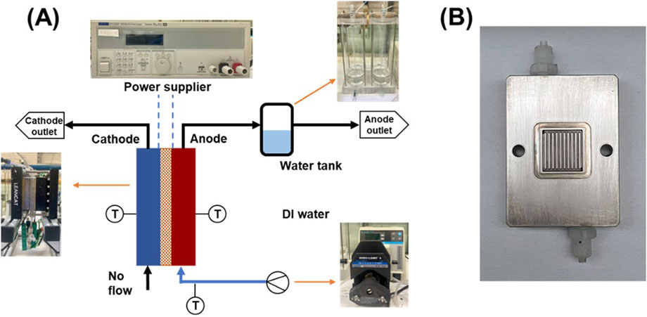
Figure 1. (A) Schematic and experimental setup of the 5 cm2 PEM water electrolyzer testing cell, and (B) The flow channels of the 5 cm2 testing cell.
Currently, most open performance data for PEMWE are obtained from the laboratory-scale evaluation, using testing cells with an active area typically ranging from 1 to 5 cm2. However, in practical stacks, the CCMs used have a minimum active area of 25 cm2, or better to be 50 cm2 or even larger (Ouimet et al., 2022). The significant difference in scale between laboratory tests and practical applications presents a major challenge in translating lab-scale results to industry-scale electrolyzers. It is known that the differences in CCM materials, their fabrication methods, catalyst distribution, and active surface areas complicate direct comparisons (Bender et al., 2019; Lickert et al., 2023), making it difficult to maintain consistency, even when using similar materials (Xu et al., 2025).
To bridge the gap, besides the CCM itself, it is also crucial to understand the influence of the CCM assembling conditions in the single cell testing, developing an optimal assembling approach that can ensure laboratory findings are applicable to industrial-scale PEMWE systems (Shi et al., 2023). Studies show that electrode fabrication techniques and assembly pressures significantly impact performance metrics like resistance and mass transfer. Achieving this requires addressing key issues such as reproducibility, comparability, and system design. Variations in measurement setups, cell configurations, and testing procedures can all influence the comparability of results (Kuhnert et al., 2023). A key factor in assembling conditions is the clamping force applied to the cell. Under strong clamping forces, porous transport layers (PTLs) are subjected to non-uniform forces due to the channel-rib configuration of the flow field. These compressive stresses can lead to PTL deformation, while the coarse surface structure of PTLs can cause indentations (micro-cracks) in the catalyst layer, resulting in higher in-plane resistances (Schuler et al., 2019) and damage to the fragile membrane, potentially leading to pinholes (Mandal and Secanell, 2022; Khajeh-Hosseini-Dalasm et al., 2014). Therefore, achieving an optimal clamping force is critical to minimizing mechanical deformation while maintaining electrochemical performance.
The first approach to mitigating these effects is modifying the channel-rib configuration to achieve a more uniform stress distribution. For instance, Liu et al. adopted a mesh flow channel to optimize the stress distribution, which was demonstrated in a 50 cm2 electrolyzer at 2 A/cm2, showing a voltage reduction of 40 mV (Liu et al., 2024). The second method is to carefully control the assembly stress. Titanium-based PTLs, being rigid materials, are less effective at redistributing compression forces compared to softer materials like carbon paper. To date, most studies investigating the influence of clamping pressure on PEMWE performance have focused primarily on the cathode-side GDL rather than the complete PTL configuration. For instance, Borgardt et al. concluded that optimal performance can be achieved when the cell operates at an average clamping pressure of 2.0–3.0 MPa on the active area by using carbon-based GDLs at the cathode side (Borgardt et al., 2019). Similarly, Cruz Ortiz et al. demonstrated that compressing carbon paper by 40% provides a balance between minimizing component deformation and maintaining low mass transport resistance with the same configuration (Cruz et al., 2024).
However, studies on clamping pressure effects for rigid titanium-based PTLs remain limited. Unlike carbon-based GDLs, titanium-based PTLs exhibit higher rigidity and lower compressibility, which leads to distinct stress distribution patterns. Further research is needed to address this gap, focusing on understanding the interplay between clamping pressure, mechanical deformation, and electrochemical performance.
In this study we compare CCMs with an active area of 5 cm2, assembling in the 5 cm2 and 50 cm2 testing cells under complete titanium PTLs, with different assembling forces, gaskets, and configurations. A CCM with an active area of 50 cm2 is then evaluated to provide insights for scaling up application. The findings highlight the impact of design factors such as assembly configuration, scaling effects, and interfacial contact on performance. By identifying these critical factors, this work lays the groundwork for optimizing large-scale PEM water electrolyzers.
2 Experimental
2.1 Catalyst-coated membranes (CCMs) fabrication
The catalyst-coated membranes (CCMs) were fabricated using a refined protocol to ensure consistency and optimal performance. Catalyst inks were prepared with iridium (Johnson Matthey) and Pt/C (TEC10E50E, Tanaka) at a concentration of 24 mg/mL and 7 mg/mL, respectively. The inks were formulated with an ionomer (D98-25BS, Solvay) at 25 wt.% (to the catalyst) for the anode side and 69 wt.% for the cathode side. These inks were dissolved in a 4:1 solution of isopropyl alcohol (Sigma-Aldrich) and deionized water (18 MΩ cm). The homemade CCMs were fabricated using the Aquivion® PFSA membrane, E98-15S, with a thickness of 150 µm.
To achieve uniform dispersion, the catalyst inks were ultrasonicated in an ultrasonic bath (GT sonic-D6) for 30 min under ice bath. Following dispersion, the inks were sprayed directly onto the membrane surface using an ultrasonic spray device (Nadetech) under a controlled nitrogen pressure of 0.1 MPa. After spraying, the CCM was dried in an oven at 60°C for 4 h to ensure complete solvent evaporation.
Hot pressing was conducted to enhance the mechanical stability of the CCM; polytetrafluoroethylene (PTFE) films were placed on both sides of the CCM. The assembly was preheated for 90 s and hot-pressed at a pressure of 1 MPa for another 90 s, with the temperature maintained at 185°C. After hot pressing, the PTFE films were peeled off, and the CCM was ready for use without any further treatment.
2.2 PEMWE testing cell-5 cm2
Initial testing was conducted using a custom-built single cell (LeanCat) with an active area of 5 cm2, as shown in Figure 1. This cell uses a parallel flow field, and each channel has a width and depth of 1 mm. Deionized water was supplied to the anode side via a peristaltic pump at a flow rate of 10 mL/min. All cell components were assembled and secured using four screws tightened with a torque force of 3.5 N·m, except during the specific experiments investigating the effect of the assembly pressure. Temperature was controlled at 80°C throughout the testing process using a temperature controller that monitored the anode, cathode, and inlet water temperatures. Before testing the CCM, a conditioning protocol was implemented to activate the electrolysis cell. The protocol involved applying a current density of 0.2 A/cm2 for 1 h, followed by an increase to 1.0 A/cm2 for an additional hour. Subsequently, the cell was operated under constant voltage conditions, first at 2.0 V for 30 min and then at 1.7 V for 2 h.
2.3 PEMWE testing cell-50 cm2
As shown in Figure 2, the large-scale testing was conducted using a Horiba-Fuelcon C50-EC water electrolyzer testing system. A 50 cm2 testing cell was used from Contango Company. This cell uses a parallel flow field with a channel width and depth of 2 mm. The cell temperature was controlled by adjusting the water temperature at 80°C in the anode circuit; All the operating and conditioning procedures were identical to those used for the 5 cm2 testing cell.
Polarization curves were recorded using constant voltage mode by monitoring the imposed cell voltage against the current density. The power supply was adjusted with a series of voltages within the potential range from 1.3 V to 2.0 V to record the variation in current. Each step was maintained for 1 min to ensure the accuracy of the recorded data. Electrochemical impedance spectroscopy (EIS) analysis was performed with a potentiostat (IviumStat.XRi) at 1.5 V under different conditions, varying the frequency from 100 kHz to 0.1 Hz with an amplitude of 10 mV.
3 Results and discussion
3.1 Assembling force
To analyze the influence of the assembling force, different torque values ranging from 2 to 4 N·m were applied, with all other operating conditions maintained constant according to the standard protocols. To facilitate the comparison, a commercial CCM (Fumea EF-10) was utilized for this testing. The CCM has an anode coated with 2 mgIr/cm2 of iridium catalysts and the cathode with 0.5 mgPt/cm2 of Pt/C.
To maximize performance and achieve consistent contact among the cell components, the assembling force was applied in a controlled, stepwise method. Starting with a lower torque force, and then gradually increasing until the required force was reached. This progressive tightening method helped to evenly distribute the pressure across the entire area of the CCM and PTL, thereby reducing the risk of localized stress or deformation, which could otherwise impair cell performance or even lead to structural damage.
As shown in the polarization curves in Figure 3, the current density at 1.8 V increases notably from 1.21 A/cm2 at an assembling torque of 2 N·m to 1.35 A/cm2 at 3 N·m. While the current density remains nearly unchanged between 3 and 3.5 N·m at 1.8 V, the highest performance is observed at 3.5 N·m at 2 V, reaching 2.41 A/cm2. Beyond this point, a slight decrease in current density occurs, dropping to 1.3 A/cm2 and 2.31 A/cm2 at 4 N·m for 1.8 V and 2 V, respectively, suggesting that excessive assembling torque force can negatively affect the cell performance. This trend suggests an optimal torque level where the increased force maximizes overall performance by enhancing physical contact. Previous studies have shown that the force applied to the CCM assembly significantly impacts electrolyzer performance by affecting the interfacial contact (Khajeh-Hosseini-Dalasm et al., 2014; Liu et al., 2024). On the other hand, insufficient assembling force could result in gas leakage and poor contact between different components, while excessive force increases the risk of damaging the CCM. These findings are aligned with existing literature that highlights the role of optimal clamping pressure in reducing interfacial resistance and enhancing electrical connectivity (Borgardt et al., 2019; Bazarah et al., 2022; Mason et al., 2013). Consequently, a torque of 3.5 N·m was selected for the subsequent tests with the 5 cm2 testing cell, balancing performance and component safety.
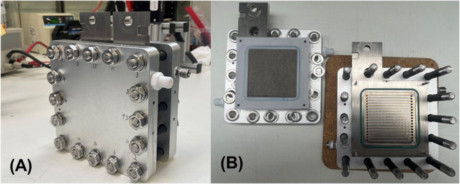
Figure 2. (A) Photograph of the assembled 50 cm2 testing cell, and (B) flow field plates showing the flow channels of the testing cell.
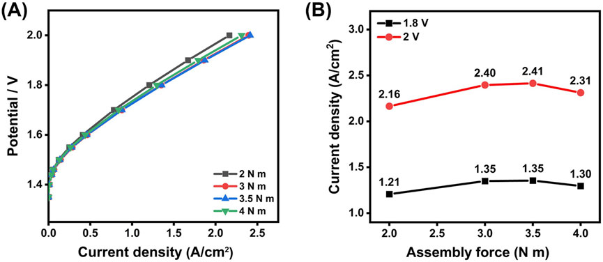
Figure 3. (A) Polarization curves for the CCM under different assembling force, and (B) comparison of the current density at 1.8 V and 2.0 V for the testing cell assembled at different torque forces.
3.2 Gasket effect
In addition to assembling force, the gasket also serves as a vital function as a sealing material, helping to prevent leakage of water and generated gases. Achieving the correct level of gasket compression is essential for optimizing contact between components, which contributes to stable cell performance (Moreno Soriano et al., 2021; Jo et al., 2020). In this study, PTFE gaskets of different thicknesses (300 μm, 250 μm, and 150 µm) were tested with platinum-coated PTLs (Bekaert, 56% porosity) applied on both the anode and cathode sides to assess their impact. This experiment is based on prior assembling force tests, with polarization curves for each gasket thickness displayed in Figure 4.
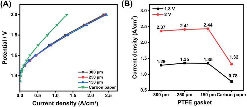
Figure 4. (A) Polarization curves obtained using PTFE gaskets of different thicknesses (300 μm, 250 μm, 150 µm), and replacing PTL with carbon paper at the cathode (B) Current density comparison at 1.8 V and 2.0 V for testing cells assembled with different PTFE gaskets, and replacing PTL with carbon paper at the cathode.
The findings indicate that gasket thickness shows only a limited impact on the overall performance of the cell. The 250 µm gasket demonstrates the best performance. Specifically, a thinner gasket (less than 150 µm) caused excessive pressure on the PTL surface, resulting in deformation and indentations, and also failed to provide an adequate seal, leading to water leakage; while with a much thicker gasket (greater than 300 µm), an extremely high assembling force is required otherwise it will result in a poor contact between CCM, PTL, and the flow field plate. A previous study suggests that an assembly pressure between 2 and 3 MPa is optimal for compressing the PTL in PEMWEs (Borgardt et al., 2019). In this experiment, a pressure of approximately 2.4 MPa is achieved by tightening four M6 screws to 3.5 N·m, and the 250 µm PTFE gasket provides effective compression and sealing under this condition.
Considering that the titanium-based PTL is a rigid material, it is less capable of redistributing compression forces compared to softer materials like carbon paper. To further investigate the impact of material properties on performance, the carbon paper (25 BA, 190 μm, Sigracet) was used to replace the cathodic PTL, and a 100 µm PTFE gasket was used to achieve a compression ratio of about 47%. The anode-side assembly configuration remained unchanged, using the previously identified optimal setup. The results for the carbon paper exhibit significantly different behavior from that of the titanium-based PTL. A substantial decrease in performance is observed, with the current density at 1.8 V dropping by approximately 44% to 0.78 A/cm2, compared to the optimal assembly. This result demonstrates that the titanium-based PTL generally exhibits superior performance compared to carbon-based GDLs. This performance advantage is attributed to the higher electrical conductivity of the titanium-based PTLs, which have a measured through-plane resistance of 10 mΩ, compared to 20 mΩ for the carbon paper GDLs, measured over an area of 5 cm2.
3.3 Testing cell with an active area of 50 cm2
Using the optimized configurations identified in the small-scale experiments, a custom 50 cm2 CCM was assembled into a large PEM water electrolysis testing cell. Three assembly methods were explored and evaluated to improve the contact behavior between various components to achieve a better power performance, based on the previous pilot test. Cross-sectional schematics of these configurations are illustrated in Figure 5.
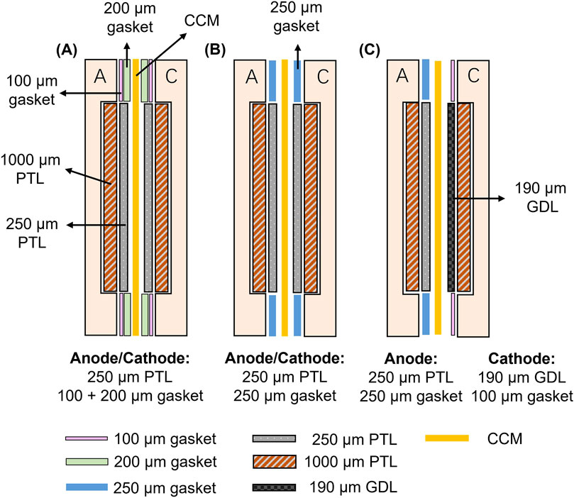
Figure 5. Cross-sectional views of different assembling methods for the 50 cm2 PEM water electrolysis testing cell (A) Assembly Method 1: Thicker PTFE gasket (300 µm) with a 250 µm PTL (B) A PTFE gasket and PTL of equal thickness (0.25 mm), which is the optimal configuration in the 5 cm2 cell, and (C) Assembly Method 3: Cathode-side titanium PTL replaced with a carbon-based GDL.
In the schematics above, “A” and “C” represent the anodic and cathodic flow field plate, respectively. The primary differences among the three assembly methods lie in the arrangement of the PTL and the thickness of the gasket. To achieve a similar compressing force as for the 5 cm2 testing cell, all methods here employed an assembly torque of 10 N·m for the 18 screws. Below is a detailed discussion of each method and its potential impact on CCM performance.
• Assembly Method 1: This approach used a thicker total 300 µm PTFE gasket to minimize excessive compression of the PTL. However, large electrolyzers typically require higher assembling forces to achieve uniform contact across the entire area, which is essential for optimal thermal, electrical, and mass transport distribution. This configuration may cause inadequate contact between components.
• Assembly Method 2: This configuration employed a PTFE gasket and PTL of equal thickness (0.25 mm), replicating the optimal setup identified in small-scale tests. By ensuring uniform pressure distribution and effective mechanical sealing, this method may balance contact resistance and component stability, contributing to improved performance.
• Assembly Method 3: This method, recommended by the manufacturer, replaced the titanium PTL with a carbon-based GDL, although this method has been confirmed not to work with the 5 cm2 testing cell. The carbon GDLs are more compressible compared to titanium PTLs. The good compressibility of the carbon paper could help to distribute pressure more evenly, ensuring better contact between the PTL and catalyst layers.
Based on the above analysis, it is evident that factors such as material compressibility, assembling force, and electrical contact distribution significantly affect overall electrolyzer performance. Additionally, the issue of membrane swelling during operation must also be considered. As the membrane absorbs water, its thickness and shape can change, potentially leading to uneven contact distribution across the cell. This uneven contact can negatively impact performance by increasing resistance or reducing stability. Therefore, in practical applications, particularly for large electrolyzers or stacks, sealing the CCM to prevent membrane swelling is crucial to maintaining consistent contact and achieving optimal performance (Moreno Soriano et al., 2021; Hjuler et al., 2016; Zhao et al., 2023). To evaluate the effect of different assembly methods on electrochemical performance, a self-prepared CCM with a 50 cm2 active area is used. The resulting polarization curves are displayed in Figure 6, providing a direct comparison of the three assembly methods under identical conditions.

Figure 6. Polarization curves under different assembling methods for a self-prepared 50 cm2 CCM.
The results show that the second assembly method delivers superior performance, consistent with observations from the 5 cm2 testing cell where the PTL and PTFE gasket share the same thickness. In this configuration, the current density reaches 1.54 A/cm2 at 1.8 V, highlighting that a moderate level of compression optimizes electrochemical performance. In comparison, the first assembly method generates the lowest performance, ascribed to poor contact between components due to the use of the thicker PTFE gasket. At 1.8 V, this configuration records a current density of only 1.17 A/cm2, underscoring the negative impact of inadequate contact. Meanwhile, the third method, which employed a carbon-based GDL on the cathode side, achieves a current density of 1.32 A/cm2 at 1.8 V. This finding reinforces the conclusion that the titanium-based PTL consistently outperforms the carbon-based GDL due to their higher conductivity, making them more suitable for high-performance applications. Thus, the second assembly method is selected as the assembly method for the 50 cm2 testing cell in the following experiment.
In addition to the assembly method, the influence of the assembling force on CCM performance is also evaluated. Various assembling torques of 4, 6, 8, and 10 N·m are applied during the tightening process. The resulting polarization curves are presented in Figure 7 below.
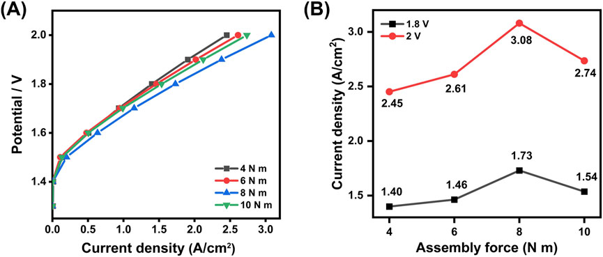
Figure 7. (A) Polarization curves under different torques for the 50 cm2 CCM (B) Comparison of the current density at 1.8 V and 2.0 V for the 50 cm2 testing cell assembled at different torque forces.
The figures above demonstrate that increasing the torque from 4 N·m to 8 N·m enhances the recorded performance of the CCM, with the current density increasing from 1.4 A/cm2 to 1.73 A/cm2 at 1.8 V. However, a further increase in torque to 10 N·m results in a decline in performance, with the current density dropping to 1.54 A/cm2. According to the manufacturer’s technical guidelines, the recommended torque range is between 10 N·m and 15 N·m with carbon-based GDL. In this study, attempts to further increase the torque led to the CCM adhering to the PTL, causing damage to the CCM. Moreover, the relatively thin design of the end plates and flow field plates poses risks of deformation under long-term high-torque conditions. Taking both performance and structural integrity into account, a torque of 8 N·m was selected to be the optimal setting for assembling the electrolyzer. Considering the 50 cm2 active area of the CCM and the 18 screws used, this assembly force and the changing trend are very similar to that in the 5 cm2 testing cell.
3.4 Bridging the small and the large electrolysis testing cell
To investigate the relationship between the small electrolysis testing cell, i.e., 5 cm2, and the large-scale electrolysis testing cell, i.e., 50 cm2, three CCMs were prepared and tested under consistent experimental conditions. The first CCM with an active area of 5 cm2 was tested in both 5 cm2 and 50 cm2 testing cells, enabling a direct comparison of performance across different scales. The second CCM, with an active area of 50 cm2, was tested in the 50 cm2 testing cell. To examine the impact of scaling effects on performance, a small piece with an active area of 5 cm2 was cut from the CCM with an active area of 50 cm2 and retested in the 5 cm2 testing cell. The polarization curves obtained for the different tests are compared in Figure 8A. To further understand the differences between small and large electrolysis testing cell setups, EIS measurements were also conducted for the CCM with an active area of 5 cm2 tested in both configurations, as shown in Figure 8B.
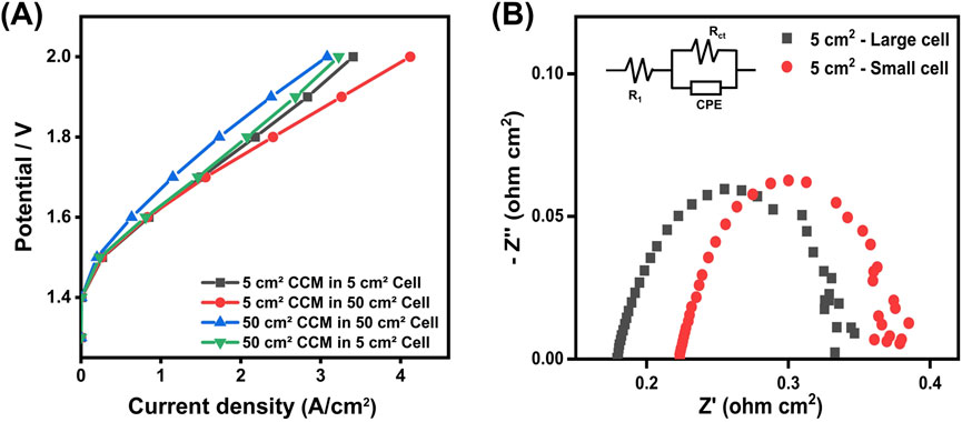
Figure 8. (A) Polarization curves for the CCMs with an active area of 5 cm2 and 50 cm2 tested in both 5 cm2 and 50 cm2 testing cells (B) Nyquist plots for the 5 cm2 CCM tested in the small and large electrolysis cells (at 1.5 V).
When comparing the testing results in the small 5 cm2 testing cell, it shows that both CCMs with the active area of 5 cm2 demonstrate very similar performance. This similarity between the directly fabricated 5 cm2 CCM and the 5 cm2 piece cut from the large 50 cm2 CCM highlights the reliability of the fabrication process.
However, the recorded performance varies a lot for the CCM tested in the two different testing cell setups. The current densities are 2.2 A/cm2 and 2.4 A/cm2 recorded for the CCM with the active area of 5 cm2 in the small and large testing cells at 1.8 V, respectively. This deviation becomes more significant in the high current density range. The Nyquist plots reveal distinct charge transfer resistance (Rct) and ohmic resistance (RΩ) characteristics between the small and large testing cells (Table 1). Because the same CCM was used, the charge transfer resistance remains consistent across two setups, which means that intrinsic material properties are unaffected by the configuration. However, the ohmic resistance differs significantly, which might be caused by the cell design such as flow field structure, assembly compression, and electrical contact resistance.
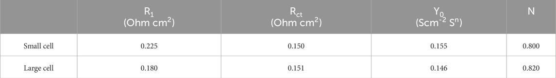
Table 1. Nyquist EIS plot parameters at 1.5 V deducted from Figure 8B.
The most notable finding is the scaling effect observed when comparing the performance recorded in the large testing cell for the CCM with both active areas, i.e., 5 cm2 and 50 cm2. Despite the same fabrication and testing procedures employed, the large CCM shows a significant decline in performance. For example, at 1.8 V, the current density drops to only 1.73 A/cm2, compared to 2.4 A/cm2 and 2.2 A/cm2 for the CCM with the active of 5 cm2 tested in the large and the small testing cells, respectively.
This scaling effect causes a decline in performance and arises from several factors. First, mass transport limitations and thermal management challenges become more pronounced when using the CCM with the active area of 50 cm2 compared to that of 5 cm2, contributing to reduced performance. Second, a larger active area increases susceptibility to uneven pressure distribution and non-uniform flow paths, leading to an increase in localized ohmic resistance. Third, membrane swelling exacerbates this phenomenon. In real applications, fluctuations in temperature and water flow rate can cause the membrane to expand or contract, leading to in-plane compression or tensile stress. This can result in improper contact between the catalyst layer and the PTL, and in severe cases, mechanical damage to the membrane (Yang et al., 2022; Ye and Zhan, 2013; Liang et al., 2017).
To further analyze the influence of key parameters on performance across different setups and scaling levels, Figure 9 summarizes the relative improvements achieved through optimization of the assembling force, assembly method, and the challenges posed by scale-up. At 1.8 V, optimizing the assembling force resulted in a 9.8% improvement, while changing the assembling method led to a significant increase of 40.6%. At 2.0 V, these optimizations provided respective improvements of 11.6% and 47.1%, respectively, highlighting the crucial role of proper assembly design in minimizing interface resistance and improving electrical connectivity. However, transitioning from a small-scale CCM to a larger one introduced performance setbacks, with a decrease of 16.8% at 1.8 V and 4.5%, at 2.0 V. These reductions highlight the persistent challenges associated with scaling up technology. The systematic examination of these effects within this study pinpoints the optimization of the assembly method as a key factor for boosting performance, while the inherent difficulties of scaling up continue to pose significant barriers for industrial application. To bridge the results from laboratory experiments to large applications, it is essential to address these challenges associated with scaling up. Reliable sealing, optimized electrolyzer design as well as cell configurations, are critical to ensuring consistent performance and preventing scaling-induced losses in performance.
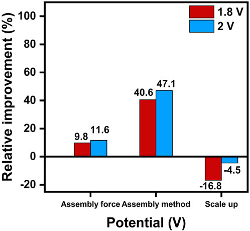
Figure 9. Relative improvement (%) in performance at 1.8 V and 2.0 V for different parameters, based on data from the 50 cm2 testing cell.
4 Conclusion
This study highlights the critical role of small water electrolysis testing cell optimization in guiding large-scale system design. By systematically adjusting key parameters, such as the assembling force, gasket thickness, and PTL type, the optimal configurations were identified to maximize performance while maintaining CCM mechanical stability. These findings provide a standardized assembly protocol that enhances reproducibility and consistency across different configurations and scales. The key findings include.
• Assembling force and gasket thickness: In the small 5 cm2 testing cell, optimal performance was achieved using a 3.5 N·m assembly torque with PTFE gaskets and PTLs of equal thickness. Both lower and higher torques resulted in performance degradation. This balance ensured robust interfacial contact without inducing structural strain on the CCM.
• Scale-up adaptation: When applied to the large 50 cm2 testing cell setup, the same PTFE gasket and PTL thickness provided consistent performance, demonstrating the scalability of the small-scale configuration. However, the specific assembling torque should be adjusted based on the overall design of the testing cell.
The results demonstrate that optimizing the small testing cell setup can be successfully applied to the large one under specific conditions, offering valuable insights for scaling. However, the complexities of scaling effects, particularly interfacial resistance and assembling force, remain key challenges. Electrochemical impedance spectroscopy measurements further revealed significant differences in ohmic resistance between the small and large testing cells, underscoring the importance of interfacial contact and system design in mitigating these losses.
Future work should focus on uncovering the mechanisms behind performance loss during scale-up. Advanced techniques such as EIS can provide deeper insights into these factors, aiding the development of more reliable and efficient large-scale PEMWEs.
Data availability statement
The original contributions presented in the study are included in the article/supplementary material, further inquiries can be directed to the corresponding authors.
Author contributions
DH: Investigation, Methodology, Writing–original draft. GQ: Conceptualization, Supervision, Writing–review and editing. LL: Investigation, Methodology, Writing–review and editing. XZ: Conceptualization, Project administration, Writing–review and editing. YY: Conceptualization, Methodology, Project administration, Writing–review and editing. SD: Conceptualization, Funding acquisition, Resources, Supervision, Writing–review and editing.
Funding
The author(s) declare that financial support was received for the research and/or publication of this article. This study is funded by the research and development project of State Grid Corporation of China (Project No: 5500-202258360A-2-0-HW). The funder was not involved in the study design, collection, analysis, interpretation of data, the writing of this article, or the decision to submit it for publication.
Conflict of interest
Authors GQ and XZ were employed by Global Energy Interconnection Research Institute Europe GmbH.
The remaining authors declare that the research was conducted in the absence of any commercial or financial relationships that could be construed as a potential conflict of interest.
The author(s) declared that they were an editorial board member of Frontiers, at the time of submission. This had no impact on the peer review process and the final decision.
Publisher’s note
All claims expressed in this article are solely those of the authors and do not necessarily represent those of their affiliated organizations, or those of the publisher, the editors and the reviewers. Any product that may be evaluated in this article, or claim that may be made by its manufacturer, is not guaranteed or endorsed by the publisher.
References
Bazarah, A., Majlan, E. H., Husaini, T., Zainoodin, A. M., Alshami, I., Goh, J., et al. (2022). Factors influencing the performance and durability of polymer electrolyte membrane water electrolyzer: a review. Int. J. Hydrogen Energy 47 (85), 35976–35989. doi:10.1016/j.ijhydene.2022.08.180
Bender, G., Carmo, M., Smolinka, T., Gago, A., Danilovic, N., Mueller, M., et al. (2019). Initial approaches in benchmarking and round robin testing for proton exchange membrane water electrolyzers. Int. J. Hydrogen Energy 44 (18), 9174–9187. doi:10.1016/j.ijhydene.2019.02.074
Bessarabov, D., Kruger, A., Luopa, S. M., Park, J., Molnar, A. A., and Lewinski, K. A. (2016). Gas crossover mitigation in PEM water electrolysis: hydrogen cross-over benchmark study of 3M’s Ir-nstf based electrolysis catalyst-coated membranes. ECS Trans. 75 (14), 1165–1173. doi:10.1149/07514.1165ecst
Borgardt, E., Giesenberg, L., Reska, M., Müller, M., Wippermann, K., Langemann, M., et al. (2019). Impact of clamping pressure and stress relaxation on the performance of different polymer electrolyte membrane water electrolysis cell designs. Int. J. Hydrogen Energy 44 (42), 23556–23567. doi:10.1016/j.ijhydene.2019.07.075
Cieluch, M., Düerkop, D., Kazamer, N., Wirkert, F., Podleschny, P., Rost, U., et al. (2024). Manufacturing and investigation of MEAs for PEMWE based on glass fibre reinforced PFSA/ssPS composite membranes and catalyst-coated substrates prepared via catalyst electrodeposition. Int. J. Hydrogen Energy 52, 521–533. doi:10.1016/j.ijhydene.2023.07.310
Cruz, O. E., van Treel, N., Koch, S., Vierrath, S., and Bühler, M. (2024). The effect of compression on PEM Electrolyzer membrane electrode Assemblies. J. Power Sources 614, 235018. doi:10.1016/j.jpowsour.2024.235018
Gao, J., Huang, X., Cai, W., Wang, Q., Jia, C., and Liu, B. (2020). Rational design of an iridium-tungsten composite with an iridium-rich surface for acidic water oxidation. ACS Appl. Mater Interfaces 12 (23), 25991–26001. doi:10.1021/acsami.0c05906
Grigoriev, S. A., Fateev, V. N., Bessarabov, D. G., and Millet, P. (2020). Current status, research trends, and challenges in water electrolysis science and technology. Int. J. Hydrogen Energy 45 (49), 26036–26058. doi:10.1016/j.ijhydene.2020.03.109
Hegge, F., Lombeck, F., Cruz Ortiz, E., Bohn, L., Von Holst, M., Kroschel, M., et al. (2020). Efficient and stable low iridium loaded anodes for PEM water electrolysis made possible by nanofiber interlayers. ACS Appl. Energy Mater 3 (9), 8276–8284. doi:10.1021/acsaem.0c00735
Hjuler, H. A., Aili, D., and Jensen, J. O. (2016). High temperature polymer electrolyte membrane fuel cells: approaches, status, and perspectives. High Temp. Polym. Electrolyte Membr. Fuel Cells Approaches, Status, Perspect., 1–545. doi:10.1007/978-3-319-17082-4_3
Holzapfel, P., Bühler, M., Van Pham, C., Hegge, F., Böhm, T., McLaughlin, D., et al. (2020). Directly coated membrane electrode assemblies for proton exchange membrane water electrolysis. Electrochem Commun. 110, 106640. doi:10.1016/j.elecom.2019.106640
Jo, M., Cho, H. S., and Na, Y. (2020). Comparative analysis of circular and square end plates for a highly pressurized proton exchange membrane water electrolysis stack. Appl. Sci. 10 (18), 6315. doi:10.3390/app10186315
Khajeh-Hosseini-Dalasm, N., Sasabe, T., Tokumasu, T., and Pasaogullari, U. (2014). Effects of polytetrafluoroethylene treatment and compression on gas diffusion layer microstructure using high-resolution X-ray computed tomography. J. Power Sources 266, 213–221. doi:10.1016/j.jpowsour.2014.05.004
Kim, T., Sihn, Y., Yoon, I. H., Yoon, S. J., Lee, K., Yang, J. H., et al. (2021). Monolayer hexagonal boron nitride nanosheets as proton-conductive gas barriers for polymer electrolyte membrane water electrolysis. ACS Appl. Nano Mater 4 (9), 9104–9112. doi:10.1021/acsanm.1c01691
Kuhnert, E., Hacker, V., and Bodner, M. (2023). A review of accelerated stress tests for enhancing MEA durability in PEM water electrolysis cells. Int. J. Energy Res. 2023 (1), 1–23. doi:10.1155/2023/3183108
Liang, P., Qiu, D., Peng, L., Yi, P., Lai, X., and Ni, J. (2017). Structure failure of the sealing in the assembly process for proton exchange membrane fuel cells. Int. J. Hydrogen Energy 42 (15), 10217–10227. doi:10.1016/j.ijhydene.2017.01.026
Lickert, T., Fischer, S., Young, J. L., Klose, S., Franzetti, I., Hahn, D., et al. (2023). Advances in benchmarking and round robin testing for PEM water electrolysis: reference protocol and hardware. Appl. Energy 352, 121898. doi:10.1016/j.apenergy.2023.121898
Liu, C., Shviro, M., Gago, A. S., Zaccarine, S. F., Bender, G., Gazdzicki, P., et al. (2021). Exploring the interface of skin-layered titanium fibers for electrochemical water splitting. Adv. Energy Mater 11 (8), 2002926. doi:10.1002/aenm.202002926
Liu, J., Liu, H., Yang, Y., Tao, Y., Zhao, L., Li, S., et al. (2024). Efficient and stable proton exchange membrane water electrolysis enabled by stress optimization. ACS Cent. Sci. 10, 852–859. doi:10.1021/acscentsci.4c00037
Liu, R. T., Xu, Z. L., Li, F. M., Chen, F. Y., Yu, J. Y., Yan, Y., et al. (2023). Recent advances in proton exchange membrane water electrolysis. Chem. Soc. Rev. 52 (16), 5652–5683. doi:10.1039/d2cs00681b
Liu, Y., Huang, S., Wang, D., Zhang, H., Shan, D., Peng, S., et al. (2022). Modifying Ti-based gas diffusion layer passivation for polymer electrolyte membrane water electrolysis via electrochemical nitridation. ACS Appl. Mater Interfaces 14 (13), 15728–15735. doi:10.1021/acsami.1c22639
Lv, X. W., Tian, W. W., and Yuan, Z. Y. (2023). Recent advances in high-efficiency electrocatalytic water splitting systems. Electrochem. Energy Rev. 6 (1), 23. doi:10.1007/s41918-022-00159-1
Mandal, M., and Secanell, M. (2022). Improved polymer electrolyte membrane water electrolyzer performance by using carbon black as a pore former in the anode catalyst layer. J. Power Sources 541, 231629. doi:10.1016/j.jpowsour.2022.231629
Mason, T. J., Millichamp, J., Shearing, P. R., and Brett, D. J. L. (2013). A study of the effect of compression on the performance of polymer electrolyte fuel cells using electrochemical impedance spectroscopy and dimensional change analysis. Int. J. Hydrogen Energy 38 (18), 7414–7422. doi:10.1016/j.ijhydene.2013.04.021
Moreno Soriano, R., Rojas, N., Nieto, E., de Guadalupe González-Huerta, R., and Sandoval-Pineda, J. M. (2021). Influence of the gasket materials on the clamping pressure distribution in a PEM water electrolyzer: bolt torques and operation mode in pre-conditioning. Int. J. Hydrogen Energy 46 (51), 25944–25953. doi:10.1016/j.ijhydene.2021.03.076
Mu, X., Yuan, Y., Yu, M., Hu, Y., Zeng, W., Peng, W., et al. (2024). Robust water/seawater-electrolysis hydrogen production at industrial-scale current densities by modulating built-in-outer electric field of catalytic substance. Nano Energy 131, 110216. doi:10.1016/j.nanoen.2024.110216
Ouimet, R. J., Glenn, J. R., De Porcellinis, D., Motz, A. R., Carmo, M., and Ayers, K. E. (2022). The role of electrocatalysts in the development of gigawatt-scale PEM electrolyzers. ACS Catal. 12 (10), 6159–6171. doi:10.1021/acscatal.2c00570
Park, J., Kang, Z., Bender, G., Ulsh, M., and Mauger, S. A. (2020). Roll-to-roll production of catalyst coated membranes for low-temperature electrolyzers. J. Power Sources 479, 228819. doi:10.1016/j.jpowsour.2020.228819
Schuler, T., De Bruycker, R., Schmidt, T. J., al, , Roy, A., Roenning, F. H., et al. (2017). Critical review—identifying critical gaps for polymer electrolyte water electrolysis development. J. Electrochem Soc. 164 (4), F387–F399. doi:10.1149/2.1241908jes
Selamet, O. F., and Ergoktas, M. S. (2015). Effects of bolt torque and contact resistance on the performance of the polymer electrolyte membrane electrolyzers. J. Power Sources 281, 103–113. doi:10.1016/j.jpowsour.2015.01.162
Shi, L., Chen, J., Zhao, S., Du, L., and Ye, S. (2023). Proton-exchange membrane water electrolysis: from fundamental study to industrial application. Chem. Catal. 3 (9), 100734. doi:10.1016/j.checat.2023.100734
Siracusano, S., Baglio, V., Van Dijk, N., Merlo, L., and Aricò, A. S. (2017). Enhanced performance and durability of low catalyst loading PEM water electrolyser based on a short-side chain perfluorosulfonic ionomer. Appl. Energy 192, 477–489. doi:10.1016/j.apenergy.2016.09.011
Stiber, S., Sata, N., Morawietz, T., Ansar, S. A., Jahnke, T., Lee, J. K., et al. (2022). A high-performance, durable and low-cost proton exchange membrane electrolyser with stainless steel components. Energy Environ. Sci. 15 (1), 109–122. doi:10.1039/d1ee02112e
Wu, Z. Y., Chen, F. Y., Li, B., Yu, S. W., Finfrock, Y. Z., Meira, D. M., et al. (2022). Non-iridium-based electrocatalyst for durable acidic oxygen evolution reaction in proton exchange membrane water electrolysis. Nat. Mater. 22 (1), 100–108. doi:10.1038/s41563-022-01380-5
Xu, J., Yang, Y., Jin, H., Zheng, Y., and Qiao, S. Z. (2025). Bridging gaps between lab- and fab-oriented anode design for proton exchange membrane water electrolyzers. Chem. 11, 102305. doi:10.1016/j.chempr.2024.09.004
Yang, D., Tan, Y., Li, B., Ming, P., Xiao, Q., and Zhang, C. (2022). A review of the transition region of membrane electrode assembly of proton exchange membrane fuel cells: design, degradation, and mitigation. Membr. (Basel) 12 (3), 306. doi:10.3390/membranes12030306
Ye, D. H., and Zhan, Z. G. (2013). A review on the sealing structures of membrane electrode assembly of proton exchange membrane fuel cells. J. Power Sources 231, 285–292. doi:10.1016/j.jpowsour.2013.01.009
Zainoodin, A. M., Tsujiguchi, T., Masdar, M. S., Kamarudin, S. K., Osaka, Y., and Kodama, A. (2018). Performance of a direct formic acid fuel cell fabricated by ultrasonic spraying. Int. J. Hydrogen Energy 43 (12), 6413–6420. doi:10.1016/j.ijhydene.2018.02.024
Zhang, K., Liang, X., Wang, L., Sun, K., Wang, Y., Xie, Z., et al. (2022). Status and perspectives of key materials for PEM electrolyzer. Nano Res. Energy 1 (3), e9120032. doi:10.26599/nre.2022.9120032
Keywords: water electrolysis, electrolyzer, proton exchange membrane (PEM), catalyst coated membrane (CCM), porous transport layer (PTL), assembling force, contact resistance
Citation: Hou D, Qiao G, Liu L, Zhang X, Yan Y and Du S (2025) Challenges in scaling up testing of catalyst coated membranes for proton exchange membrane water electrolyzers. Front. Energy Res. 13:1557069. doi: 10.3389/fenrg.2025.1557069
Received: 08 January 2025; Accepted: 26 February 2025;
Published: 14 March 2025.
Edited by:
Shanwen Tao, University of Warwick, United KingdomCopyright © 2025 Hou, Qiao, Liu, Zhang, Yan and Du. This is an open-access article distributed under the terms of the Creative Commons Attribution License (CC BY). The use, distribution or reproduction in other forums is permitted, provided the original author(s) and the copyright owner(s) are credited and that the original publication in this journal is cited, in accordance with accepted academic practice. No use, distribution or reproduction is permitted which does not comply with these terms.
*Correspondence: Yichang Yan, y.yan.1@bham.ac.uk; Shangfeng Du, s.du@bham.ac.uk