 Weiwei Yao1,2
 Jie Zhao
 Jinqiu Dou
- 1Laboratory of Hydro-Wind-Solar Multi-Energy Control Coordination, Wuhan, China
- 2Science and Technology Research Institute, China Three Gorges Corporation, Beijing, China
- 3Hubei Engineering and Technology Research Center for AC/DC Intelligent Distribution Network, School of Electrical Engineering and Automation, Wuhan University, Wuhan University, Wuhan, China
The transient overvoltage caused by faults in ultra-high-voltage direct current (UHVDC) transmission lines and alternating current (AC) systems can adversely affect system safety and stability. This study theoretically analyzes the transient overvoltage generation mechanism caused by DC single-pole ground faults and typical fault conditions in two different cases by combining the DC line and AC system of the transmitting side. Considering the different generation mechanisms of the two transient overvoltages, the main factors affecting transient overvoltages were determined to be the DC line ground fault location, DC filter main capacitance, AC system short-circuit ratio, and DC transmission power. Finally, through a simulation of UHVDC transmission engineering, the relationship between various influencing factors and overvoltage was obtained, which can provide guidance in transmission engineering UHVDC design.
1 Introduction
The ultra-high-voltage direct current (UHVDC) power transmission system provides the benefits of power transmission over long distances and large capacity, which can solve the problem of resources and energy being distributed reversely in China through large-scale energy allocation optimization (Li et al., 2015; Shen et al., 2021; Wang et al., 2014; Guo et al., 2024). UHVDC transmission systems have complex wiring and comprise many devices; therefore, overvoltage can occur in various ways (Zheng et al., 2012). Overvoltage refers to the phenomenon where the voltage in electrical equipment or power systems exceeds its normal operating voltage. Overvoltage mechanisms in DC transmission systems can be classified into two categories: external and internal (HVDC transmission system design, 2015). The overvoltage produced by the thunder intruded by a lightning tower or line is the external overvoltage, and the overvoltage produced by the short-circuit fault on the AC side or transformer, filter throwback, reclosing, and other human operations is the internal overvoltage, which can be classified into frequency and operational overvoltages. Overvoltage adversely affects the safe and stable operation of the UHVDC transmission system and causes the fan to go off-grid, thereby affecting the supply reliability of the AC system. Consequently, studying the overvoltage generation mechanism and its influencing factors is essential to confining the overvoltage within the permissible scale.
Domestically, research has been conducted on the overvoltage of UHVDC transmission lines. The electromagnetic induction characteristics of the fault pole to the health of UHVDC transmission lines (Wang and Siye, 2015) and the distribution law of overvoltage formation mechanism along the DC line fault (Wu et al., 2009) have been analyzed. In Liu et al. (2017), the design scheme of the DC filter for ± UHVDC transmission system was systematically introduced, and the factors influencing the DC-side operating voltage peak, including the main capacitance value, shunt resonance frequency, filter resistance value, and filter resistance wiring were studied. However, this article neglects the impact of factors such as the converter station terminal impedance, transmission line length, and line parameters on the overvoltage of the DC line. In Yang et al. (2020), the mechanism of the DC-side overvoltage generation in the UHVDC system in wind farms under single pole ground fault was studied. However, the article does not clearly identify the main factors contributing to the occurrence of overvoltage. The above research results on DC line single-pole ground fault overvoltage calculation are based on stage parameters from an actual engineering feasibility study, ignoring some important parameters such as the DC filter type and others impacting overvoltage.
For typical fault conditions such as phase change failure and DC blocking that cause transient overvoltage, in Tu et al. (2017) the transient reactive power characteristics at the beginning and end of the DC transmission system were investigated during DC phase change failure. However, the article only studied the power conversion during the fault period and did not explore its influencing factors in depth. In Li et al. (2014), the transient overvoltage producing mechanism in the sending grid that resulted in phase change failure was studied, and the connection between transient overvoltage and the number of AC filters was analyzed. However, the article gives insufficient consideration to other factors that may affect overvoltage. In Krishayya et al. (1997), the relationship between short-circuit ratio and transient overvoltage was analyzed, providing reference values for transient overvoltage according to different system strengths. In Wang et al. (2016), the influencing factors of transient overvoltage during DC blocking by the AC system equivalence method were analyzed, and the transient overvoltage calculation method of the converter bus was studied for a blocked DC line. The existing literature on the working condition transient characteristics of typical faults in DC systems mainly focuses on the transient change of electrical quantities, such as power and voltage, and research on the calculation, influencing factors, and modeling of transient overvoltage at the transmitting side is lacking (Cao et al., 2019).
In this study, for the internal overvoltage of a DC transmission system, the different generation mechanisms of both transient overvoltages were considered in combination with the DC line and transmitting AC system. As the analysis of overvoltage influencing factors is not sufficiently comprehensive in existing research (Bai et al., 2023), this study analyzes the relationship between each influencing factor and transient overvoltage, thereby proposing a feasible plan to limit the coincident overvoltage amplitude, which has certain guiding significance for the parameter design of DC transmission project-related equipment.
2 Mechanism of DC transmission overvoltage generation under fault conditions
Under normal conditions, the equipment in the system operates at the rated voltage, but faults can still occur. A fault on one pole of the DC transmission line will cause an operational overvoltage on the other pole. Pressurizing the line under no-load conditions can lead to an open-circuit overvoltage, which may damage the electrical equipment (Lu et al., 2023).
2.1 DC line overvoltage generation mechanism
The normal operating state of the DC system is bipolar, such that in case of a positive pole ground fault, a transient overvoltage is induced by the transmission line electromagnetic coupling phenomenon in the health pole. A fault in the middle point of the line causes a secondary superposition of voltage jumps on the health line, triggering the most serious overvoltage. The following section analyzes the mechanism of DC-line overvoltage generation based on the characteristics and processes of traveling wave transmission.
A simplified schematic of the bipolar operation of the DC transmission system is shown in Figure 1 (Zhang et al., 2019). The main components are the AC system equivalent power supply, converter bus, converter station, flat-wave reactor, DC filter, and DC line.

Figure 1. Simplified schematic diagram of DC transmission system.
When a DC system ground fault occurs at one pole, the voltage on the fault pole drops to zero, which is equivalent to a traveling voltage wave of amplitude U0 propagating along the fault pole line and generating a current wave propagating to both ends of the converter station, as shown in Figure 2 (Xing et al., 2019).
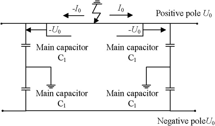
Figure 2. Fault pole voltage and current traveling wave transmission process.
When the voltage wave reaches both sides of the converter station, the DC filter main capacitor generates a larger sudden pulse current, together with a sudden pulse of current at the fault point. This is because the electromagnetic coupling between the poles induces a reverse pulse current at the health pole, and the health pole capacitance to ground continues to charge, thus increasing the voltage, which corresponds to the primary and secondary voltage jumps superimposed on the normal operating voltage, generating a serious overvoltage phenomenon at the health pole.
Let the forward voltage wave be
Depending on the nature of the impedance at the converter station, the reflected wave can be expressed as Formulas 2–4:
In the formulas,
2.2 Phase change failure causes transient overvoltage at the sending end of the grid
When the inverter side of the DC system fails to suppress the rapidly rising DC current, the rectifier increases the trigger angle. The reactive power consumed by the rectifier also increases, and the voltage of the sending grid temporarily decreases (Peng Zhen et al., 2020). As the trigger angle of the rectifier increases, the DC current decreases to zero (Ouyang et al., 2024); the reactive power used by the converter decreases; and the reactive power compensation provided by the filter returns to the transmission grid in large quantities, causing a transient overvoltage in the transmission grid. Figure 3 shows the voltage phase diagram of the AC line. The DC current continues to drop; the AC current phase changes; the active power drops; and the excess reactive power from the rectifier station is transferred to the sending grid, resulting in a lower-voltage transverse component and a higher-voltage longitudinal component. Thus, a transient overvoltage is generated on the converter bus. In the figure,
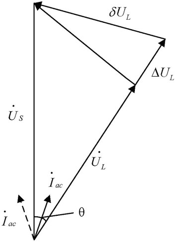
Figure 3. AC line voltage phase diagram Transient overvoltage caused by DC blocking.
When single-stage or bipolar blocking occurs in a DC system, as in the case of phase-change failure, the active power delivered by the DC decreases, resulting in a corresponding decrease in the reactive power consumed by the converter station (Fu et al., 2019; Zhang et al., 2021). The delayed action of the reactive power compensation device causes a large surplus reactive power to surge into the sending or receiving end of the grid, causing a transient voltage rise in the converter bus, with a standard value expressed as Formula 5:
where
3 Factors affecting transient overvoltage under fault conditions
The overvoltage caused by grounding or short-circuit faults on the DC and AC sides of a UHVDC transmission system and typical operating conditions caused by the faults are affected by various factors, including the location of the ground fault, main capacitance of the DC filter (Peng Long et al., 2020), short-circuit ratio of the AC system, equivalent potential, and DC transmission power. The effects of these factors on the transient overvoltage are analyzed below.
3.1 Factors affecting overvoltage of single-pole ground fault in DC lines
3.1.1 Ground fault location
The severity of the overvoltage caused by a ground fault depends on the location of the fault pole. DC-line ground fault generation can be divided into two stages:
1) Line fault is instantaneously generated when fault pole amplitude suddenly changes in the pulse-voltage traveling wave, but with opposite polarity, propagated to both sides of the converter station; the fault occurs when the voltage is zero.
2) When the voltage wave reaches the beginning and end of the converter station, the main capacitor of the DC filter returns to the discharge state and excites the pulse current.
Assuming that the fault occurs in the middle of the line, the impulse current wave in the health pole back propagates to induce the same reverse pulse current and charge the main capacitor; both ends of the pole line causing overvoltage are superimposed in the middle of the line, where the amplitude of the overvoltage is the highest.
3.1.2 DC filter main capacitor
The generation of a healthy full overvoltage results from the charging of the DC filter ground capacitor (Liu et al., 2020); therefore, the main capacitance parameters of the DC filter also has an impact on the overvoltage caused by the DC line ground fault, which is subsequently analyzed and discussed in conjunction with the voltage jump generation mechanism.
3.2 Factors influencing the transient overvoltage caused by typical operating conditions
Phase change failure and DC blocking have similar overvoltage generation mechanisms, and the factors affecting the transient overvoltage are the same. The DC transmission system on the transmitting side is illustrated in Figure 4;

Figure 4. AC/DC system equivalent circuit at the sending end.
where,
where the equivalent reactance is shown in Equation 7:
The AC system short-circuit capacity is shown in Equation 8:
After a phase-change failure on the inverter side or a DC blocking fault on the transmitting side, the DC transmission power decreases; the reactive power consumed by the converter decreases; and the excess reactive power provided by the reactive power compensation device is returned to the AC system. This causes the converter bus voltage to increase, and a transient overvoltage
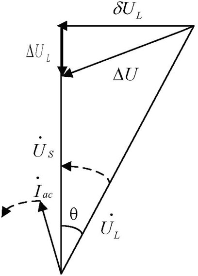
Figure 5. Phase diagram of AC line voltage during DC blocking.
Concurrently, the reactive power compensation capacity also increases with an increase in voltage. The relationship between the two is
As the transverse component of the system voltage has a small effect on the overvoltage amplitude, it is ignored, thereby solving for Formula 10.
In this expression, the transient overvoltage
4 Simulation and analysis
4.1 The simulation model
In this study, power systems computer-aided design/electromagnetic transients including DC (PSCAD/EMTDC) simulation software was used to build a simulation model in the context of the ±800 kV UHVDC transmission project (Yuan et al., 2024). Figure 6 shows the schematic diagram of the principal structure of the ±800 kV UHVDC transmission system with the rated operating parameters shown in Table 1 (Luo et al., 2019).
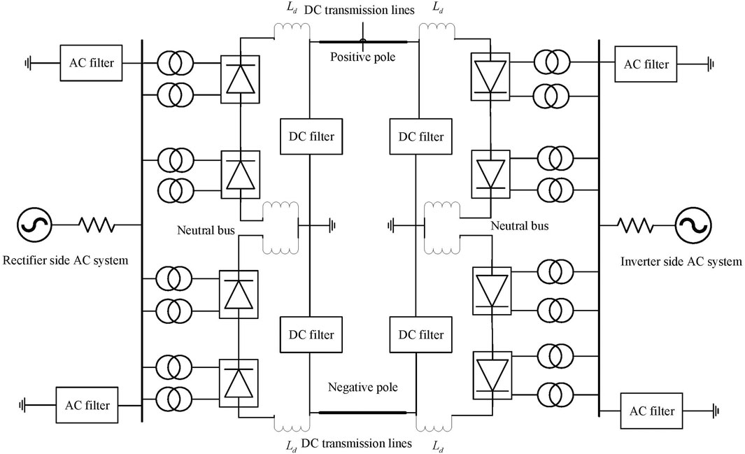
Figure 6. Schematic diagram of the structure of Zhaqin UHVDC transmission.

Table 1. Rated operating parameters.
The built simulation model was tested for bipolar full-voltage operation, and the voltage and current conditions on the rectifier and inverter sides were simulated. Table 2 lists the steady-state operating parameters for the bipolar full-voltage operation mode.
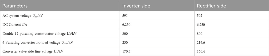
Table 2. Steady-state operating parameters for bipolar full-pressure operation mode.
Figure 7 shows that the voltages and currents on both the rectifier and inverter sides are 1 p.u. in the bipolar full-voltage operation mode, indicating that the proposed model conforms to actual operations and provides a basis for the subsequent simulation study.
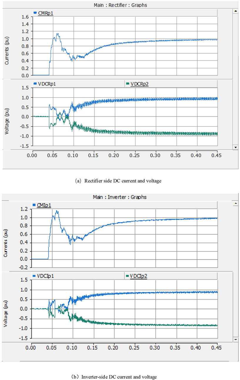
Figure 7. DC pole line current and voltage for bipolar full voltage operation.
4.2 DC line overvoltage influence factor analysis
4.2.1 Impact of ground fault location
To explore the impact of the ground fault location on the overvoltage amplitude of the fault pole line, a single pole ground fault was set at 0, 25%, 50%, 75% and 100% along the line from the rectifier to the inverter side of a pole line, and the fault time lasted 0.1 s. The different ground fault locations on the sound pole line along the overvoltage is shown in Figure 8.
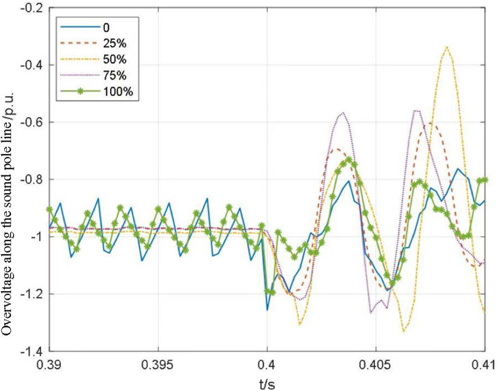
Figure 8. Different ground fault location sound pole line along the overvoltage.
According to the simulation results, when a single-pole ground fault occurs, the health pole generates two voltage jumps at the instant of the fault and 5 ms after fault occurrence. When the location of the single-pole ground fault is at 50% of the line from the rectifier to the inverter side, i.e., at the midpoint of the line, the overvoltage reaches its maximum magnitude of 1.3 p.u. at the corresponding location of the health pole. Furthermore, the location of the fault point is in the middle of the line, and the overvoltage amplitude is smaller, indicating that the location of the ground fault affects the overvoltage at the health pole.
4.2.2 Effect of DC filter main capacitor
The DC filter used in the ±800 kV UHVDC project was a thrice-tuned passive filter, and the circuit diagram is shown in Figure 9.
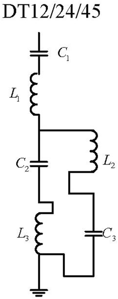
Figure 9. Three-tuned passive filter.
Referring to the parameters of DC filters in actual engineering, the main capacitor C1 is usually 1–4 μF; C2 and C3 are usually 1–5 μF. Simulation analysis was performed for the overvoltage caused by the ground fault occurring on the single line when C2 = 1 μF and C3 = 1 μF.
Based on Figures 10, 11 and the Tables 3, 4, when C2 or C3 is 1 μF, the overvoltage gradually decreases with an increase in C1. The changes in C2 and C3 do not significantly affect the overvoltage, indicating that the main capacitor C1 of the DC filter is the main factor of the single pole ground fault influencing the overvoltage of the DC line.
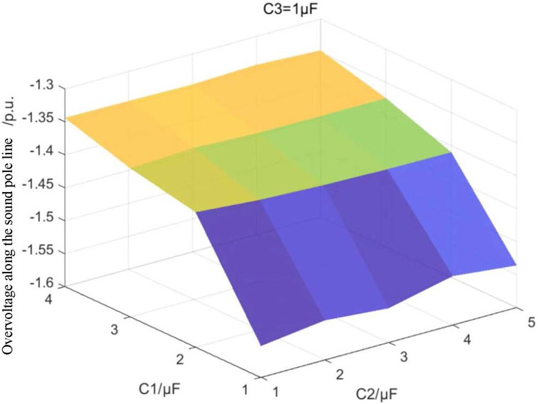
Figure 10. Effect of DC filter capacitance on overvoltage (Overvoltage at C3 = 1 μF).
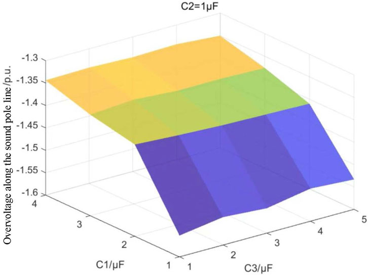
Figure 11. Effect of DC filter capacitance on overvoltage (Overvoltage at C2 = 1 μF).

Table 3. Effect of C1/C2 on overvoltage (C3 = 1 μF).
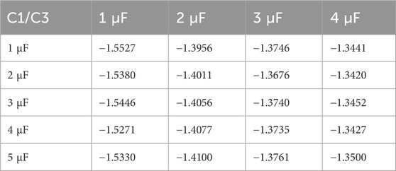
Table 4. Effect of C1/C3 on overvoltage (C2 = 1 μF).
Next, the main capacitor parameters are further explored in relation to the fault and health pole pulse currents, overvoltage, and main capacitance.
As shown in Figures 12, 13, the discharge current of the DC filter and the overvoltage at the sound pole increase with an increase in the main capacitor C1, further verifying that the overvoltage on the sound pole line is caused by the discharge current generated by the sound pole ground capacitor that is charged by the main capacitor of the DC filter through the electromagnetic coupling that occurs in both pole lines.
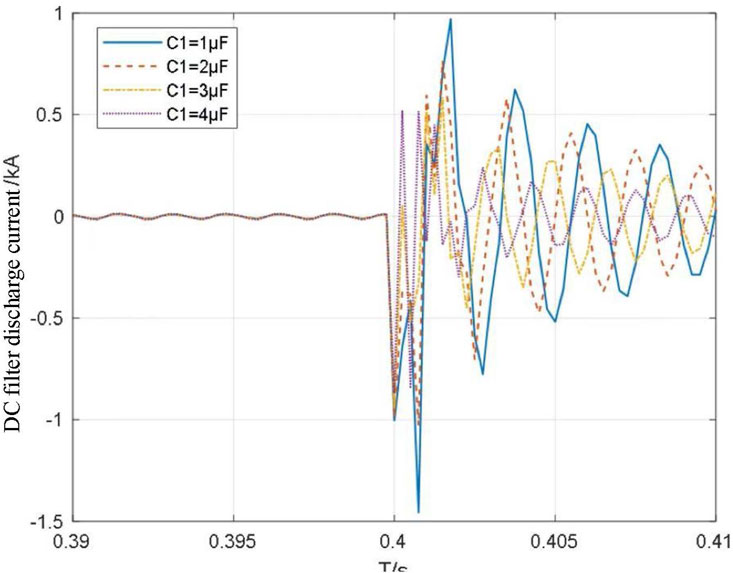
Figure 12. DC filter discharge current versus main capacitance.

Figure 13. Health pole overvoltage versus main capacitance.
4.3 Transient overvoltage influence factor analysis for typical operating conditions
4.3.1 Effect of short-circuit ratio
The initial short circuit ratio of the feeder grid was 2.5. The system short-circuit ratio was changed by adjusting the internal impedance of the AC power supply to alter the magnitude of the equivalent reactance
In Figure 14, the transient overvoltage caused by phase change failure in a system with a short-circuit ratio of 2.5 reaches 1.19 p.u., which increases by 0.11 p.u. compared with the overvoltage of 1.08 p.u. at a short circuit ratio of 7.5. The larger the short circuit ratio, the stronger is the AC system strength, and the smaller is the amplitude of the transient overvoltage and change, which also increase nonlinearly. Therefore, measures to improve the strength of an AC system are beneficial for the stable operation of the system.

Figure 14. Effect of system short-circuit ratio on transient overvoltage.
4.3.2 Effect of DC transmission power
Letting the AC system at the transmitting end be 2.5, the DC transmission power was changed to observe the change in transient overvoltage.
According to Figure 15, the outcome reflects that the change in the DC transmission power has a relatively small effect on the highest value of the transient voltage, and the transient overvoltage caused by the phase-change failure occurs at a power of 1.0 p.u. and reaches approximately 1.25 p.u. The higher the power, the higher is the transient overvoltage. Therefore, high-capacity DC transmission should be avoided in a weak system, or the system strength should be increased during high-capacity transmission.

Figure 15. Effect of DC transmission power on transient overvoltage.
5 Conclusion
In this study, to explore the transient overvoltage problems caused by DC single pole ground fault and typical fault conditions, a theoretical analysis was conducted on the mechanism of overvoltage generation in two different cases. The influencing factors of transient overvoltage were deduced, and the PSCAD/EMTDC electromagnetic transient simulation software was used to model and perform calculations for the ±800 kV UHVDC transmission project. By simulating and analyzing the relationship between each influencing factor and overvoltage, the following conclusions were reached:
1) By analyzing the mechanism of DC line overvoltage generation, it was concluded that the health pole line overvoltage is caused by the pulse current wave generated under the action of electromagnetic coupling to the ground capacitor charging. If a fault occurs in the line, the midpoint overvoltage is superimposed, and the size of the current is related to the main capacitance of the DC filter.
2) In typical fault conditions, such as phase change failure and DC blocking, a reduction in the active DC power delivery leads to a large amount of surplus reactive power flooding into the grid at the transmitting or receiving end, causing a transient overvoltage at the transmission converter bus, which is mainly related to the AC system short-circuit ratio and transmitted DC power, as derived from the overvoltage formula.
3) Simulations were conducted to analyze the relationship between the ground fault, main capacitor parameters, and health pole transient overvoltage of the DC lines. The further the fault point was from the middle of the line, the lower was the amplitude of the overvoltage, reaching the maximum at the midpoint. By comparing the main capacitor C1 with the change in C2 and C3, C1 was determined to be the main influencing factor of overvoltage, and the overvoltage varied positively with an increase in the main capacitor C1.
4) A simulation-based analysis of the relationship between the AC system short circuit ratio, DC transmission power, and transient overvoltage at the transmission end of the grid, revealed that the larger the short-circuit ratio, the lower was the amplitude of the overvoltage, whereas the larger the DC transmission power, the higher was the overvoltage, and the short-circuit ratio was greater than the DC transmission power on the overvoltage. Therefore, large-capacity DC transmission should be avoided under a weak system to improve system strength.
Data availability statement
The raw data supporting the conclusions of this article will be made available by the authors, without undue reservation.
Author contributions
WY: Conceptualization, Writing–original draft. JZ: Formal Analysis, Writing–review and editing. JD: Validation, Writing–review and editing. YD: Supervision, Writing–original draft. YuL: Project administration, Writing–original draft. YiL: Methodology, Writing–original draft. JC: Funding acquisition, Writing–original draft.
Funding
The author(s) declare that financial support was received for the research, authorship, and/or publication of this article. This work was supported by the Key Research and Development Program of Hubei Province, project “Key Technology Research on Watershed Hydro-Wind-Solar Multi-Energy Complementary Integration” (Project No.: 2022AAA007), and by a project from China Yangtze Power Co., Ltd., project “Impact and Simulation Research on Wind-Solar Integration on Power Systems and Plant Operation” (Contract No.: Z242302010).
Conflict of interest
Authors WY, YD, YL, and JC were employed by China Three Gorges Corporation. The authors declare that this study received funding from China Yangtze Power Co., Ltd. The funder had the following involvement in the study: design, data collection, analysis, decision to publish and preparation of the manuscript.
The remaining authors declare that the research was conducted in the absence of any commercial or financial relationships that could be construed as a potential conflict of interest.
Publisher’s note
All claims expressed in this article are solely those of the authors and do not necessarily represent those of their affiliated organizations, or those of the publisher, the editors and the reviewers. Any product that may be evaluated in this article, or claim that may be made by its manufacturer, is not guaranteed or endorsed by the publisher.
References
Aragüés-Peñalba, M., Egea-Àlvarez, A., Gomis-Bellmunt, O., and Sumper, A. (2012). Optimum voltage control for loss minimization in HVDC multi-terminal transmission systems for large offshore wind farms. Electr. Power Syst. Res. 89, 54–63. doi:10.1016/j.epsr.2012.02.006
Bai, S., Jiang, X., Chang, H., Wang, C., Tian, Z., Tian, G., et al. (2023). Review of transient overvoltage in UHVDC transmission sending-end system 2023 5th international conference on power and energy Technology: 5th international conference on power and energy Technology (ICPET 2023), 27-30 july 2023. Tianjin, China, 378–387.
Cao, Z., Li, X., Yao, R., Fan, X., Shi, X., and Wang, X. (2019). “Calculation method of transient overvoltage of sending-side grid caused by commutation failure,” in 2019 IEEE 3rd international electrical and energy conference: CIEEC 2019, Beijing, China, September 7–9, 2019. IEEE, 1952–1956.
Fu, M., He, Y., and Yin, Z. (2019). Performance analysis of reactive power compensation device at weak sending end in HVDC system. Proc. CSU-EPSA 31 6, 129–136. doi:10.19635/j.cnki.csu-epsa.000053
Guo, X., Li, X., Wang, Q., and Li, P. (2024). Status and thoughts on the development of ultra high voltage direct current (UHVDC) transmission technology. New Type Power Syst. 2.03, 237–250. doi:10.20121/j.2097-2784.ntps.240034
Krishayya, P. C. S., Adapa, R., and Holm, M. (1997). IEEE guide for planning DC links terminating at AC locations having low short-circuit capacities. part I: AC/DC system interaction phenomena. France: CIGRE.
Li, X., Liu, Y., Li, T., and Chen, S. (2014). “Study on the impact of commutation failure on AC voltage of rectifier-side in UHVDC,” in IEEE international conference on power system Technology (Chengdu, China).
Li, S., Wang, X., Wang, Z., and Hu, Y. (2015). Control system design for UHVDC hierarchical connection to AC grid. Proc. CSEE 35 (10), 2409–2416. doi:10.13334/j.0258-8013.pcsee.2015.10.006
Liu, H., Wen, J., Yu, S., Li, J., and Wang, t. (2020). “Research on design of DC filter systems of multiterminal DC transmission systems,” in 2020 4th international conference on HVDC (HVDC). Xi'an, China, 46–51.
Liu, Z., Yu, J., Guo, X., Fu, Y., Ji, Y., and Liu, J. (2017). Research of 1100kV UHVDC project simplified DC filter. Proc. CSEE 37 (21), 6347–6352. doi:10.13334/j.0258-8013.pcsee.170643
Liu, J., Jiang, R., Li, Q., Zhang, L., and Wang, R. (2018). “Study on transient overvoltage of wind farm caused by fault of HVDC system and its suppression measures,” in 2018 2nd IEEE conference on energy internet and energy system integration (EI2). Beijing, China, 1–6.
Lu, Z., Jin, H., Zhang, H., Wang, H., Li, X., and Ma, Z. (2023). “Simulation study of transient overvoltage at HVDC transmission terminal,” in 2023 3rd new energy and energy storage system control summit forum: 3rd new energy and energy storage system control summit forum (NEESSC). Mianyang, China, 452–455.
Luo, H., Le, J., and Mao, T. (2019). Analysis of operational characteristics of Zalut-Qingzhou ±800 kV UHVDC transmission project. Electr. Power Autom. Equip. 39.1, 53–59.
Ouyang, J., ChenYujie, P. X., and Diao, Y. (2024). An improved suppression method of AC transient overvoltage for line commuted converter based high voltage direct current considering AC-DC system coupling. Electronics 13 (10), 1844. doi:10.3390/electronics13101844
Peng, L., Tang, Y., Zhao, B., Li, Y., Cheng, F., and Liu, Y. (2020b). “Transition process and influencing factors of AC transient overvoltage subject to HVDC disturbances,” in 2020 12th IEEE PES asia-pacific power and energy engineering conference (APPEEC). Nanjing, China, 1–5.
Peng, Z., Zhang, S., Sun, Y., Xu, J., Zhou, J., and Ren, L. (2020a). “Dynamic reactive power compensation in multi-infeed HVDC power grid considering transient stability,” in 2020 IEEE 4th conference on energy internet and energy system integration (EI2). Wuhan, China, 1059–1064.
Shen, Z., Xiong, H., Zhu, J., Shao, C., Xu, H., and Qiu, W. (2021). Modelling and analysis on evaluation factor sets affecting the safe and high-efficiency operation of UHVDC transmission project. Power Gener. Technol. 42 (01), 48–59.
Tu, J, Zhang, J., Zeng, B., Liu, M, Yi, J., and Bu, G. (2017). HVDC transient reactive power characteristics and impact of control system parameters during commutation failure and recovery. High. Volt. Eng. 43 (07), 2131–2139. doi:10.13336/j.1003-6520.hve.20170628005
Wang, X., Wei, X., Ning, L., and Wang, X. (2014). Integration techniques and transmission schemes for off-shore wind farms. Proc. CSEE 34 (31), 5459–5466.
Wang, F., Liu, T., Ding, Y., Zeng, Q., and Li, X. (2016). Calculation method and influencing factors of transient overvoltage caused by HVDC block. Power Syst. Technol. 40 (10), 3059–3065. doi:10.13335/j.1000-3673.pst.2016.10.019
Wang, D., Lv, P., Ruan, S., Lei, X., Wang, H., Ma, Q., et al. (2015). Effect of mutual inductance between bipolar transmission lines of UHVDC and proposal of countermeasure. Proc. CSEE 35 (17), 4353–4360. doi:10.13334/j.0258-8013.pcsee.2015.17.009
Wu, Y., Jiang, W., Zhu, Y., Li, X., and Wo, H. (2009). Research on inner overvoltage in UHVDC transmission line caused by flashover to ground fault. Power Systerm Technol. 33 (04), 6–10+27.
Xing, C., Liu, M., He, X., and Xi, X. (2019). “Research on flexible control technology of HVDC,” in 2019 IEEE 8th international conference on advanced power system automation and protection (APAP). Xi'an, China, 1186–1190.
Yang, N., Cui, W., Wang, Z., Li, W., Niu, S., Liu, C., et al. (2020). Research on transient characteristics of monopolar grounding fault for wind power integrated UHVDC. High. Volt. Appar. 56 (02), 142–149+157. doi:10.13296/j.1001-1609.hva.2020.02.021
Yuan, Y., Li, J., Lyu, P., Qian, Z., Jiang, Y., and Wang, J. (2024). Fault characterization for AC/DC distribution networks considering the control strategy of photovoltaic and energy storage battery. Batteries 10 (7), 259. doi:10.3390/batteries10070259
Zhang, H., Liu, Y., Yao, Y., Wang, Z., Zhang, B., and Du, Y. (2019). “Overvoltage simulation research of UHVDC transmission converter caused by upper converter midpoint bus grounding fault,” in 2019 IEEE 3rd conference on energy internet and energy system integration: EI2 2019, Changsha, China, November 8–10, 2019. Institute of Electrical and Electronics Engineers, 2218–2221.
Zhang, Y., Dong, C., and Liu, Q. (2021). “Low voltage ride through control strategy considering transient overvoltage in wind power HVDC transmission system,” in 2021 3rd asia energy and electrical engineering symposium (AEEES). Chengdu, China, 396–401.
Zheng, X., Tai, N., Yang, G., and Tu, G. (2012). Modeling and simulation of UHVDC system. Electr. Power Autom. Equip. 32 (7), 10–14.
Keywords: UHVDC, transient overvoltage, mechanism analysis, short-circuit ratio, fault conditions
Citation: Yao W, Zhao J, Dou J, Deng Y, Li Y, Liang Y and Chen J (2025) Generation mechanism and influencing factors of transient overvoltage on ultra high-voltage direct current transmission. Front. Energy Res. 13:1461365. doi: 10.3389/fenrg.2025.1461365
Received: 08 July 2024; Accepted: 23 January 2025;
Published: 18 February 2025.
Edited by:
Shabana Urooj, Princess Nourah Bint Abdulrahman University, Saudi ArabiaReviewed by:
Adel Rawea, Sana’a University, YemenAli Alshehri, King Abdulaziz City for Science and Technology, Saudi Arabia
Copyright © 2025 Yao, Zhao, Dou, Deng, Li, Liang and Chen. This is an open-access article distributed under the terms of the Creative Commons Attribution License (CC BY). The use, distribution or reproduction in other forums is permitted, provided the original author(s) and the copyright owner(s) are credited and that the original publication in this journal is cited, in accordance with accepted academic practice. No use, distribution or reproduction is permitted which does not comply with these terms.
*Correspondence: Jie Zhao, amllel93aHVAd2h1LmVkdS5jbg==