
95% of researchers rate our articles as excellent or good
Learn more about the work of our research integrity team to safeguard the quality of each article we publish.
Find out more
ORIGINAL RESEARCH article
Front. Energy Res. , 30 January 2025
Sec. Smart Grids
Volume 13 - 2025 | https://doi.org/10.3389/fenrg.2025.1430142
 Rashid Hussain Chandio1*
 Madad Ali Shah1
 Abdul Aziz Memon1
 Khawaja Haider Ali1
 Jahangeer Badar Soomro1
 Basem Alamri2Ahmed Althobaiti2
 Mohammed Alqarni3*
Designing Voltage Source Converter (VSC)-based DC grids presents a significant challenge in providing dependable and cost-effective protection against short-circuit faults. Given the increased vulnerability of high-voltage DC (HVDC) lines to the faults, there is a dire need for enhanced protection equipment capable of effectively handling fault currents. By limiting the rapid increase in fault current, fault current limiters (FCLs) reduce the requirement for complex DC circuit breakers (DCCBs) design in order to isolate faults. This paper presents a novel Hybrid FCL for the protection of large scale VSC-HVDC. It provides a comprehensive analysis of DCCBs and their impact on VSC-HVDC projects with and without FCLs. It further analyses an extensive discussion comparing DCCBs equipped with FCLs to those without FCLs. For simulation analysis, an equivalent circuit modeling approach of the Zhoushan HVDC Project is used to analyze current behavior of FCL-equipped breakers. The paper presents the circuit diagram and operational principles of the proposed FCL. Subsequently, it analyzes the FCL performance with its current limiting features and outlines the parameter design requirements necessary for its implementation. Simulation results utilizing PSCAD/EMTDC are provided to validate various aspects of this research. Further, the performance of the proposed FCL is compared with existing solutions proposed in the literature. From theoretical and simulation validations, it is concluded that DCCBs equipped with FCLs outperform conventional DCCBs without FCLs for higher-rated VSC-HVDC projects.
DC transmission is a critical component of modern power systems. It provides a reliable and efficient solution for grid connections, and long-distance power transfer (Kangwa et al., 2017). HVDC grids based on updated technology of VSC, that is modular multilevel converter (MMC), have more benefits than traditional line commutated converter (LCC) and conventional two-level VSC-based HVDC transmission network. These advantages include independent control of active and reactive power, low-harmonic distortion, ease of forming a multi-terminal DC (MTDC) system, etc., (Zhang et al., 2016). Due to its ability to resolve the issue of integrating large-scale renewable energy sources, the MMC-HVDC grid has gained attention as a center of study in recent years. A significant challenge in developing and expanding DC grids is the low impedance and absence of a zero crossing point in DC fault currents (Yan et al., 2024; Muniappan, 2021). To effectively manage fault currents caused by short circuits, various types of direct current circuit breakers (DCCBs) are considered the most effective solution (Barnes et al., 2020). DC circuit breakers (DCCBs) are categorized into three types: mechanical circuit breakers (MCBs), solid-state circuit breakers (SSCBs), and hybrid circuit breakers (HCBs). Hybrid circuit breakers have garnered increased attention because they combine the advantages of both SSCBs and MCBs. HCB performs quickly like SSCB and has the same low conduction losses as MCB (Huo et al., 2022). In 2012 ABB Grid and ALSTOM Grid developed an HCB that has useful characteristics for fault current isolation (Kolli and Rana, 2024; Nguyen et al., 2016).
However, they face limitations in terms of capacity when it comes to raising the current rating of DC grids. Two potential solutions to address this issue are adding FCLs in series with DCCBs or changing the DCCB’s design to allow for high-level fault currents (Mei et al., 2021). The only objective of FCLs in DC grids is to lower the requirements and improve the performance of DCCB. In essence, FCL has two basic functions: it keeps the fault current below a certain threshold and removes faults from the power system. During normal operation, an FCL maintains very low impedance. However, it introduces significant impedance under fault conditions, thereby limiting the increase in fault current within the system.
FCLs improve power grid reliability and stability by suppressing fault currents. When combined with DCCBs, they help protect HVDC lines from high fault currents. While FCLs cannot fully isolate faults, they are effective in limiting them. Modern FCLs remain inactive under normal conditions, making them ideal for high-power, fault-current handling systems. An ideal FCL features low impedance in normal operation, high impedance during faults, fast fault current limitation, automatic activation, and quick recovery. It should also be reliable, safe for operators, and compact for high-power and DC applications. There exist three categories of FCLs: (I) the superconducting FCL (SCFCL), (II) the non-superconducting FCL (NSFCL), and hybrid fault current limiters (Zhang et al., 2019; Singh et al., 2022). FCLs can operate as standalone circuits to reduce fault current. Additionally, FCL characteristics can be integrated into breaker designs to achieve fault-current limiting capabilities. In addition to these methods, certain controller-based approaches have also been employed for fault current suppression (Zhang et al., 2020). Among these methods, breaker-based methods are widely regarded as the most reliable option.
Authors in Ruiz et al. (2015) provided an updated review for resistive type SFCLs. They focus on the various methods for numerically modeling their local physical properties and the concepts that have already been tested in experiments. The work presents a comparison of the characteristics and properties of various resistive-type superconducting capacitors (SFCLs) made of various superconducting materials. Chen et al. (2019) proposes a strategy employing a combination of resistive-type SFCL (RSFCL) and DCCB to protect a multi-terminal DC grid from fault currents. Simulation results illustrate that the RSFCL notably reduces fault current and consequently DCCB requirements during fault scenarios. In Chen et al. (2021) the resistance of the SFCL is adjusted to lower the DCCB requirements and maintain stable and safe operation in the DC network. A concept for the design and analysis of a saturated iron core SFCL is presented in Dao et al. (2020). This study investigates various options for the SI-SFCL’s coil system and uses physical experiments to confirm its operating features. The findings from this investigation can help develop large-scale SI-SFCLs for high-voltage direct current (HVDC) power systems. Lee et al. (2018) conducts a comparative analysis among SI-based SFCL, RSFCL, and iron-core SFCL, focusing on their current-limiting and energy dissipation characteristics. The study reveals that the SI-SFCL demonstrates superior performance with notably lower energy dissipation and rapid recovery characteristics during faults. In Didier et al. (2015), a comparative assessment was conducted between inductive and resistive SFCLs, evaluating their effectiveness in current limitation and power system transient stability. The investigation demonstrates the superiority of the resistive SFCL across both domains, showing its enhanced performance in fault current limitation and power system transient stability. However, their use requires high-temperature superconducting materials and an expensive cooling system, thus making them unsuitable for DC grid deployment. A novel arrangement of current-limiting inductors (CLIs) is presented in Li et al. (2019) for use in DC grids. In both normal and fault states, these CLIs are ordered in series and parallel, respectively. This configuration effectively reduces the amplitude of the fault current. However, it simultaneously increases interruption speed and energy dissipation. The authors present a high-inductance DC reactor-based SSFCL intended for DC network applications in Heidary et al. (2019). Two coupled inductors with low and high impedance make up this arrangement. To provide a low inductance and reduce power loss, the high-inductance inductor is bypassed under normal operation. Whereas, during fault conditions, it is placed into the fault current path to offer a high inductance path. Notably, the study does not address the DCCB’s energy dissipation and interruption speed. Authors in Fu et al. (2020) and Khorasaninejad et al. (2022) introduce mutual inductance (MI) and resistive MI-current limiting circuits to alleviate the demands on DCCBs, as well as to decrease fault current magnitude and interruption speed. However, these circuits exhibit low interruption speed.
Researchers have undertaken numerous investigations into hybrid FCLs aimed at enhancing their fault current suppression capabilities. The hybrid FCL, which combines the advantages of two other topologies, appears to be a promising choice for HVDC transmission systems. Zhu et al. (2020) introduces a new design for a hybrid SFCL incorporating a biased magnetic field, featuring two-stage current limiting capabilities. Experimental findings demonstrate that the current limiting ratio achieves 89.66%, confirming the efficacy of the design and highlighting the potential application of this hybrid SFCL. Jiang et al. (2014) introduces a bridge-type HFCL utilizing MOSFETs and IGBTs to ensure rapid dynamic response. A model rated at 220 V/1 kA was built and tested. The HFCL design effectively limits fault currents in both transient and steady-state conditions. A new hybrid FCL based on a novel theory called the push-pull technique is introduced in Zhang et al. (2019). This FCL aims to enhance current limiting capabilities by mitigating the rate of rise and peak of fault currents. In Yuan et al. (2015), a novel hybrid saturated core type FCL that makes use of permanent magnets and DC coils is presented. The efficiency of the suggested FCL in clipping fault current is illustrated through simulation results. It is mentioned how the value of the limiting reactor affects the performance of FCL. A hybrid fault current limiter using liquid metal for large-scale power systems is developed in Wang et al. (2022). The authors assert that this FCL attains minimal operational losses by utilizing a fast mechanical switch, magnetic induction module, and multiple liquid metal units. Ahmad et al. (2020) introduces an incremental fault current-limiting circuit featuring multiple parallel branches designed to gradually reduce fault current during fault conditions. Each branch within this topology comprises a limiting inductor in series with a bidirectional switch. A new hybrid superconducting FCL incorporating controlled solid-state component is shown in Xingguang et al. (2020). The results of the simulation show that the suggested hybrid FCL successfully limits fault currents to less than a quarter of a half-cycle even when thyristors are used. Similarly, a new approach to current limitations is presented in Hamada et al. (2023), which uses a capacitor to absorb energy from the commutation circuit during the interruption process in conjunction with a superconducting fault current limiter to reduce short-circuit currents. The results of the experiments demonstrated that the system could isolate errors within a very short period, which was a significantly faster response than other systems that were described in the relevant research.
There are numerous digital circuit breakers available that operate at very high frequencies and provide precise fault current control (Yin et al., 2022). However, FCL-based breakers offer several advantages over these digital systems. These include superior fault current management, enhanced protection for equipment, and reduced stress on circuit breakers. Additionally, FCL-based breakers support selective coordination, contribute to greater system stability, and seamlessly integrate with existing infrastructure, making them a valuable choice in many electrical applications. They also offer the benefits of lower power loss during normal operation and reduced electromagnetic interference (EMI). Unlike digital systems that require continuous monitoring and control, FCLs operate passively under normal conditions and only activate under fault conditions. This can result in lower operational complexity and increased reliability.
This paper mainly provides the knowledge and importance of FCLs integrated within DCCBs to efficiently manage short-circuit faults in high-voltage direct current (HVDC) systems with increased ratings. This paper proposes a novel hybrid FCL with a hybrid DCCB to limit the DC fault current while ensuring high interruption speed. It offers a high-impedance path to limit the fault current under a fault condition and a low-impedance path in a steady-state condition. Furthermore, this approach incorporates two freewheeling paths aimed at dissipating the stored energy of limiting inductors through a discharging resistor. This feature limits the fault current and reduces the Metal Oxide Arrester (MOA) energy dissipation, and voltage drop across the DCCB. In short, this FCL provides high interruption speed and significantly reduces the peak of the fault current. It further limits the fault current in the current limiting stage effectively which improves the system stability. Energy absorbed by the breaker is lower with this FCL which reduces the stress on the components. The effectiveness of the proposed approach is evaluated within the PSCAD/EMTDC software environment under the DC short circuit fault condition. The obtained results are compared with those presented in Ahmad et al. (2022) and Li et al. (2019) to illustrate the effectiveness of the proposed approach. A comparative analysis reveals that the proposed method outperforms both Ahmad et al. (2022) and Li et al. (2019), and demonstrates its superior effectiveness.
The first hybrid DCCB was introduced by the ABB Company in 2012. In this setup, the ABB hybrid DCCB is connected in series with the HFCL. The diagram in Figure 1 illustrates the schematic representation of the ABB’s HDCB.
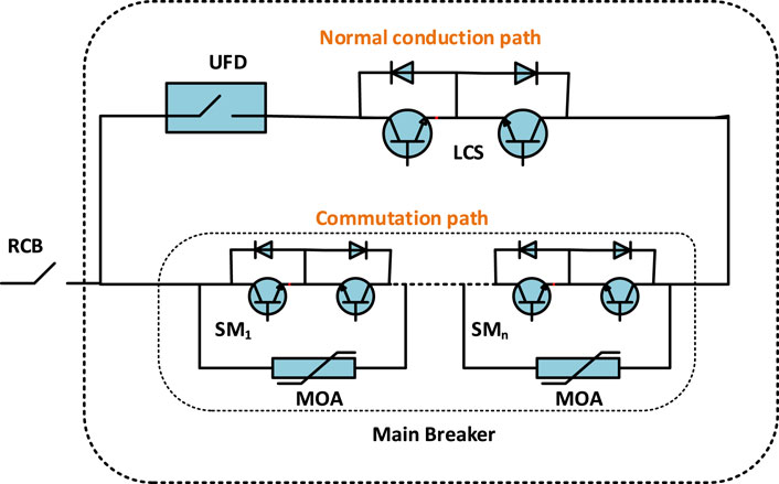
Figure 1. ABB hybrid DCCB (Callavik et al., 2013).
The conventional HCB setup typically includes three main components: a residual current breaker (RCB), a load current branch, and a main breaker (MB), as illustrated in Figure 1. The load current branch consists of a series arrangement comprising the ultra-fast disconnector (UFD) and load commutation switch (LCS). Within the MB, there are multiple Insulated Gate Bipolar Transistor (IGBT)-based Semiconductor Modules (SMs) connected in series, alongside metal oxide arresters (MOA). In high-voltage applications, it is common for the number of SMs associated in series to be quite high, possibly reaching hundreds. However, this can significantly increase industrial costs. The primary function of the RCB is to physically separate the faulty line once the process of current interruption is complete. When the hybrid CB receives a trip signal from the protection system, it activates the MB while deactivating the LCS. Consequently, fault current begins to flow into the MB (Liu et al., 2023). Once the fault current in the load current branch reaches zero, the UFD initiates the opening process. After it finishes its opening operation, the MB is deactivated, and the fault current is directed to the arresters for dissipation. The main role of the RCB is to physically separate the faulty line once the current interruption process concludes. Upon receiving a trip signal from the protection system, the HCB activates the main breaker (MB) while deactivating the LCS). As a result, fault current starts to flow into the MB. The UFD will initiates the opening process when the current in the load current branch reaches to zero. After completion of opening process of UFD the main breaker will be deactivated and hence the fault current redirected to the MOAs for dissipation.
The proposed FCL Topology is shown in Figure 2.
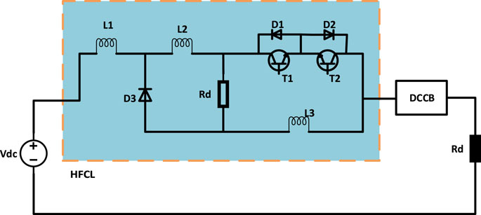
Figure 2. Topology of proposed FCL.
It comprises one LCS, a discharging resistor (R), a Diode D3, and three limiting inductors, L1, L2, and L3. The LCS includes components T1, T2, D1, and D2. The current-limiting characteristics with FCL are illustrated in Figure 3 by period P0-P4.
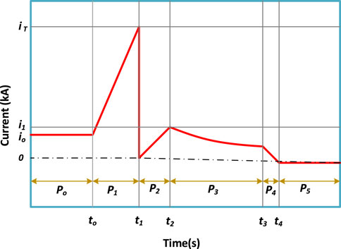
Figure 3. Current-limiting characteristics with FCL.
Figure 4 depicts the equivalent circuit of the proposed FCL, while the period interval P0 is illustrated in Figure 3. In this stage, the line current
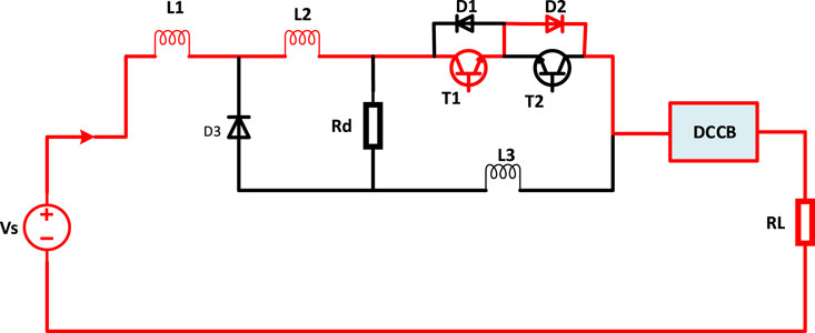
Figure 4. Equivalent circuit for steady-state/normal operation stage.
From the above equation, the
To calculate the power loss of an FCL under normal operating conditions, we need to consider the specific type of FCL and its design parameters. Generally, the power loss
where:
For some types of FCLs, this resistance might be very low or close to zero. So, in this research the power losses are considered negligible under normal operating condition.
The equivalent circuit in this period is depicted in Figure 5. It appears that during the period marked as
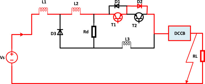
Figure 5. Equivalent circuit for fault raising stage.
According to the equivalent circuit and applying the KVL formula, the equations ca be:
or,
where,
Current in other lines is zero in this stage, therefore, from Equation 4 the current can be written as:
When the fault current within interval P1 reaches the threshold value ith at time t1, the FCL triggers the opening of the LCS. Consequently, the diode (
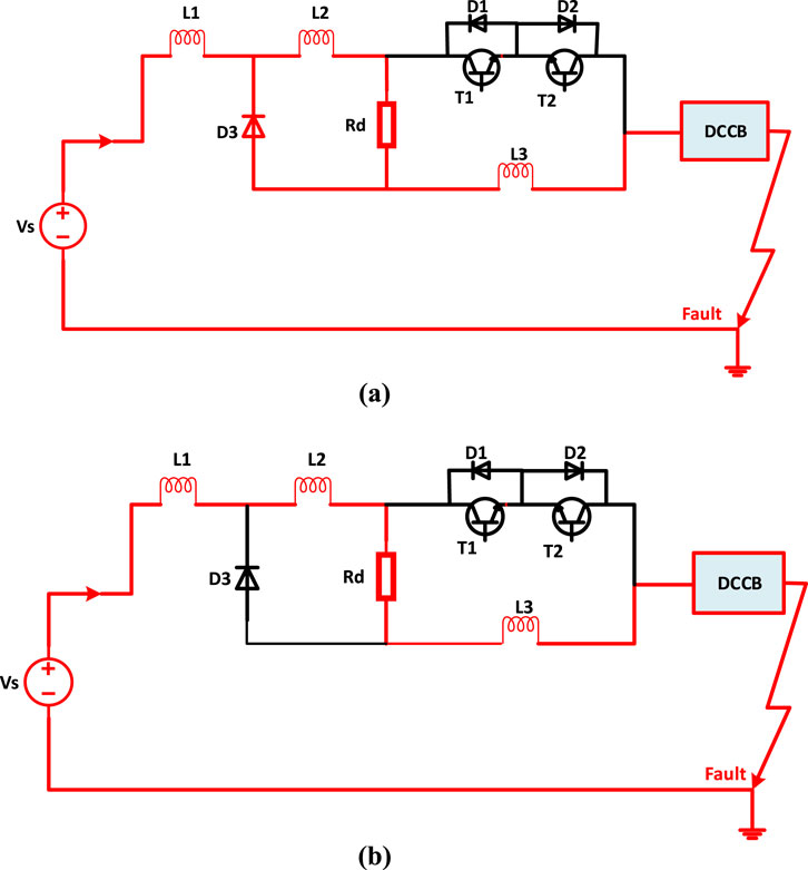
Figure 6. Equivalent circuits for fault current-limiting stage. (A) During interval P2. (B) During interval P3.
These occurrences correspond to intervals P2 and P3 in Figure 3. The KVL equations can be calculated as:
where, Rd = Discharging resistor and
The described period commences when the DCCB is opened to isolate the fault, denoted by
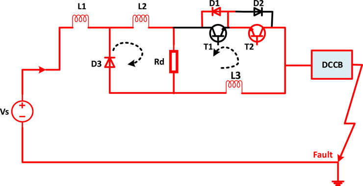
Figure 7. Equivalent circuit for fault recovery stage.
The currents flow through
The selection of the discharging resistor Rd and the limiting inductors (L1, L2, and L3) plays a crucial role in designing the FCL. Parameters such as the rate of increase and the magnitude of the fault current are utilized to determine the appropriate values for the FCL parameters. To meet the requirements of the DCCB, the following key factors are taken into account:
a) During the current limiting period, it’s essential to ensure that the maximum value of the DC fault current remains below the maximum interrupting current of the DCCB. Mathematically it can be written:
b) The response time (
c) The rate of increase in fault current must be lower than the rate of increase in DCCB current. FCLs are designed to limit the rise in fault current, allowing sufficient time for the DCCB to interrupt the DC fault current. This requirement is expressed as follows:
d) The inductance of the limiting inductors plays a crucial role in determining the rate at which the fault current rises. Specifically, the inductance of
According to Equation 10, Equation 11 can be written as:
Therefore, Lg can be written as:
e) To control the fault current during the limiting period, selecting Rd is critical. The value of Rd must be determined to satisfy the following equation i e., Equation 9.
To validate the efficiency of the proposed FCL, simulations are conducted using PSCAD/EMTDC simulations, and the results are subsequently explained. In this work, the equivalent circuit modeling approach of the Zhoushan MMC-based HVDC grid is taken into account for simulation analysis. The equivalent circuit parameters are presented in Table 1.
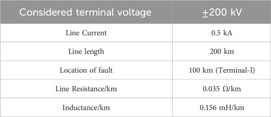
Table 1. Equivalent circuit parameters for Zhoushan HVDC grid.
For analysis, the block diagram depicted in Figure 8 illustrates the positioning of breakers with FCL between two terminals: Terminal T-1 and T-2. The short circuit fault is located on line at a specified distance from T-1.
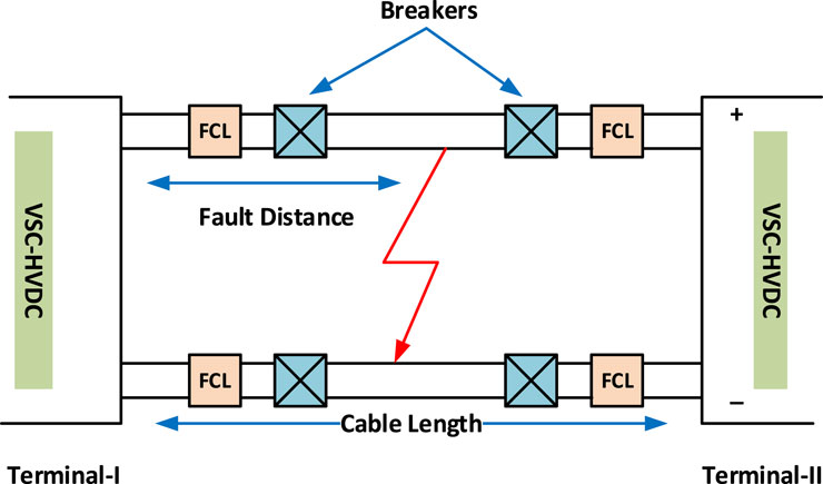
Figure 8. A block diagram demonstrating the simulation design.
The simulated results are categorized into two categories. The first category depicts the results of a traditional HCB lacking when the fault occurs in the DC grid. Meanwhile, the second category demonstrates the effects of an HCB with FCL under similar fault conditions, and both sets of results are compared. Three important results are presented to highlight the importance of DCCBs equipped with FCLs. These results involve the direct voltage, current, and power consumed by the MOA within the DC breaker.
Figures 9A–C depicts the results of current, voltage and power absorption respectively with conventional HCB under fault condition. The analysis of the current response in Figure 9A reveals several observable events. Initially, from 0 to 0.2 s, the system operates under steady-state conditions, with the current maintaining a standard value of 0.5 kA in the given case study. At 0.2 s, a short-circuit fault occurs, precisely 100 km away from the T-I. Following this, the current experiences a rapid rise from its rated value, at a rate of 3.5 kA per millisecond. Within 2 milliseconds, the current touches to approximately 16 kA. Following this transient phase, precisely at 0.202 s, the fault within the system is formally verified. In the absence of a FCL component in the conventional breaker, the current is increasing rapidly. By 0.204 s, the current peaks at approximately 16 kA, a notably substantial value. In contrast, if a FCL is implemented, the fault current undergoes a significant reduction, dropping to nearly 1 kA. As shown in the following Figure 10.

Figure 9. Results with conventional HCB without FCL under fault conditions (A) Current (B) Voltage (C) Power dissipation.
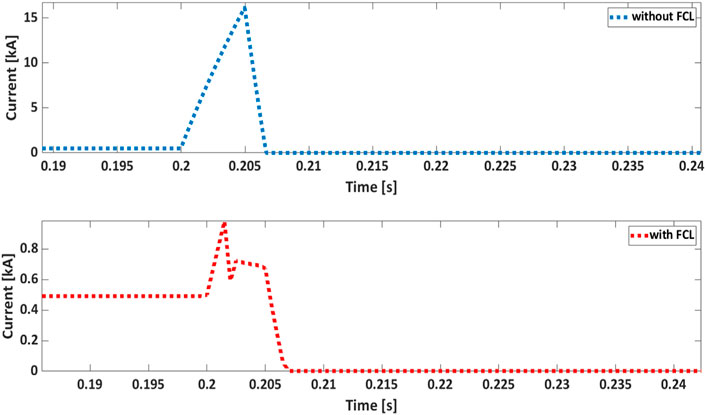
Figure 10. Line current with FCL and without FCL.
Following 0.204 s, the residual current is rerouted to the Metal Oxide Arrester (MOA) integrated across the breaker in this study to contain the fault current. Analysis of the data from Figure 10 reveals that at the end of limitation period (0.206 s) of fault current, the residual current in the HCB equipped with FCL is lower compared to that of the HCB lacking FCL. This observation indicates that arrester in the conventional HCB lacking FCL dissipates a greater amount of energy compared to breakers with FCL as shown in the power dissipation results.
Figure 11 illustrates the power dissipation of arrester in a breaker equipped with FCL.
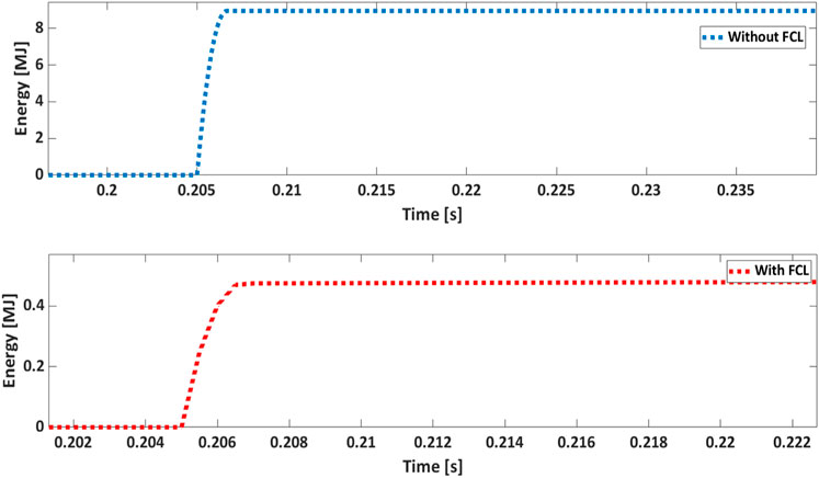
Figure 11. Power dissipated by MOA with FCL and without FCL.
In describing the behavior of voltage across the breaker elements (excluding FCL), it is noted that without the presence of a fault current limiting component, transient voltage spikes are only evident in the last stage, particularly when the current is directed to the MOA. Conversely, the behavior of voltage across the breaker components with FCL is outlined differently. In Figure 12 (without FCL), during the period 0–0.2 s, the breaker works within normal working parameters, resulting in no noticeable voltage drop across the breaker components during this phase. At 0.2 s, a system experiences a fault. However, during this period, the current flow path remains consistent with the previous stage, leading to no observable voltage drop until 0.204 s. After 0.204 s, a transient voltage spike is consistently observed across the breaker with FCL as shown in Figure 12 (with FCL). This spike is expected due to the switching action and the incorporation of Current Limiting Impedances (CLIs). When the current is directed to the MOA as indicated by the results; the voltage across it reaches the rated voltage of DC terminal, particularly evident in the case of FCL. Regarding FCL, it is important to highlight that certain current-limiting elements persist in the circuit during operational as well as non-operational phases. Consequently, a minor voltage drop is observed in last stage. To improve the transient voltage performance for breakers equipped with FCLs, it is suggested to increase the voltage ratings of the MOA.
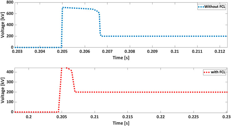
Figure 12. Response of voltage with FCL and without FCL.
Evaluating the effectiveness and competitiveness of the proposed breaker with the FCL component, it is compared with other existing solutions. This comparative analysis aims to assess the performance and viability of the HCB-FCL system with alternative methods. FCL proposed in Ahmad et al. (2022) and Li et al. (2019) are considered to compare with their performance in this scenario. The parameters of the simulated system are presented in Table 1, corresponding to this scenario. The results depicted in Figure 13 represent the DC current flowing through the system across three distinct scenarios. In Figure 14, the voltage response across the breaker is illustrated, while Figure 15 presents the power absorbed by the MOA across various solutions. Regarding Figure 13, here are the summarized details of the discussed results: At 0.2 s, a fault occurs within the system. Subsequently, for a duration of 2 milliseconds, the current is permitted to pass through the main branch of the breaker, as discussed in Ahmad et al. (2022) and Li et al. (2019) as well as through the proposed scheme. During this period, it is evident that both the rate of increase of the current and the maximum value of the current for both the Ahmad et al. (2022) and Li et al. (2019) and the proposed scheme are identical. The limiting inductors in FCL are identical, resulting in uniform characteristics within interval P1 across all scenarios. As depicted in Figure 13, fault current surges to 3, 2.5, and 1.2 kA for Li et al. (2019) and Ahmad et al. (2022) and proposed one respectively precisely at 2.002 s. At this moment, all analyzed FCLs introduce their impedance into the fault path by opening their LCSs during fault conditions. At 0.202 s, the fault current amplitudes decrease to 1.5, 0.6, and 0.5 kA for scenarios Li et al. (2019) and Ahmad et al. (2022) and the proposed one respectively. Following the opening of HCB, the fault current amplitude decreased to zero across all cases. It can be concluded from the results that the proposed solution has more current limiting capability than that of the Ahmad et al. (2022) and Li et al. (2019).
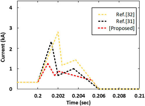
Figure 13. Results of Current with FCL (Ahmad et al., 2022; Li et al., 2019) and proposed one.
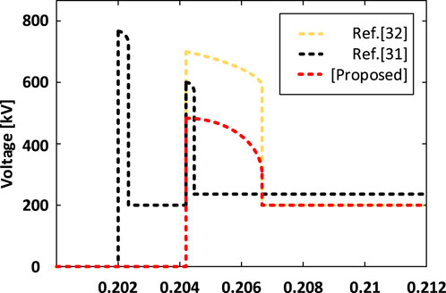
Figure 14. Response of the breaker voltage.
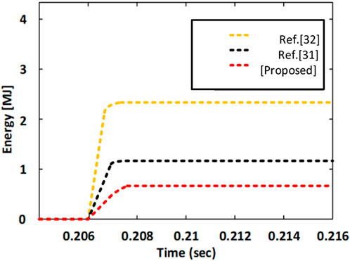
Figure 15. Power dissipated by MOA.
Figure 14 illustrates the response of the breaker voltage for various cases. Among them, three responses are highlighted in the results: one corresponds to the configuration described in Ahmad et al. (2022) another involves the use of FCL as detailed in Li et al. (2019) and the third shows the proposed configuration. The behavior of voltage across the breaker components differs among cases. In scenarios where none of the fault current limiting elements are utilized in the breaker, transient voltage spikes are primarily evident in the final phase when the current is commutated to the MOA. However, in cases involving configurations detailed in Ahmad et al. (2022) and Li et al. (2019) and the proposed setup, the voltage across the breaker components follows a distinct pattern. From 0 to 0.2 s, the breaker functions under normal operational conditions, hence no observable voltage drop occurs across the breaker components during this stage.
At 0.2 s, the system experiences a short-circuit fault, but the current flow path remains unchanged from the previous stage. Consequently, there is no voltage drop until 0.202 s. Following this, a spike of transient voltage is noted for Ahmad et al. (2022) which is expected due to switching actions and the use of Current Limiting Inductors (CLIs). Another spike of voltage is observed upon redirecting the residual current to the MOA. The results indicate that the voltage across MOA reaches the DC-rated terminal voltage when the current is redirected to the MOA, particularly in the case of Li et al. (2019) and the proposed one. Regarding Ahmad et al. (2022) it is important to observe that certain current limiting elements persist in the circuit during operational as well as non-operational stage. Consequently, a slight voltage drop is observed at the last stage. From Figure 14, it is evident that during this stage, the voltage across the proposed HCB is superior to the other two cases. The results presented in Figure 15 illustrate the power absorbed by the main arrester under various fault conditions, highlighting that the main arrester in the proposed HCB absorbs less energy compared to the others. Further, the Table 2 summarized the performance evaluation of the proposed FCL with others in literature
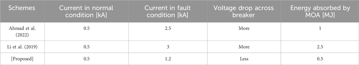
Table 2. Performance Evaluation of the proposed solution.
Based On the results presented in Figures 13–15, it was determined that the proposed FCL effectively improves the performance of HCB and surpasses the performances of the solutions outlined in Ahmad et al. (2022) and Li et al. (2019) in all aspects.
This research examines the significance of FCLs in DC Circuit Breakers, particularly in VSC-HVDC projects with higher ratings. The proposed FCL can carry line current during normal operation and effectively limits the rising rate of fault current by utilizing limiting inductors during the rising period. By incorporating limiting inductors and a resistor into the fault path, the system attenuates the fault current, bringing it down to zero by the end of the interval. This arrangement also helps decrease the fault current level throughout the limiting period. The system offers two freewheeling paths with a limiting resistor to dissipate the energy absorbed by the limiting inductors. Hence enhancing the energy absorption index and the interrupting speed of the breaker for the period of isolation. To assess the effectiveness of this solution, the DC grid with parameters from the Zhoushan Grid is used to test its performance. Furthermore, its effectiveness is assessed by comparing its performance with the solutions outlined in the literature. The comparative analysis demonstrates that the proposed solution exceeds the requirements for DCCBs in terms of both current limiting capacity and energy absorption index. The results clearly demonstrate that this solution offers significant advantages for handling fault current in large-scale VSC-HVDC systems. In the future, there is ample opportunity in the literature to explore more on fault current limiters for managing fault conditions in DC systems.
The original contributions presented in the study are included in the article/supplementary material, further inquiries can be directed to the corresponding authors.
RC: Writing–original draft, Writing–review and editing. MS: Supervision, Writing–review and editing. AbA: Methodology, Writing–review and editing. KA: Investigation, Writing–review and editing. JS: Software, Writing–review and editing. BA: Formal Analysis, Investigation, Writing–review and editing. AhA: Validation, Writing–review and editing. MA: Resources, Software, Writing–review and editing.
The author(s) declare that financial support was received for the research, authorship, and/or publication of this article. This research was funded by Taif University, Saudi Arabia, Project No. (TU-DSPP-2024-128).
The authors extend their appreciation to Taif University, Saudi Arabia, for supporting this work through project number (TU-DSPP-2024-128).
The authors declare that the research was conducted in the absence of any commercial or financial relationships that could be construed as a potential conflict of interest.
All claims expressed in this article are solely those of the authors and do not necessarily represent those of their affiliated organizations, or those of the publisher, the editors and the reviewers. Any product that may be evaluated in this article, or claim that may be made by its manufacturer, is not guaranteed or endorsed by the publisher.
Ahmad, M., Wang, Z., Shafique, M., and Nadeem, M. H. (2022). Significance of fault-current-limiters and parameters optimization in HVDC circuit breakers for increased capacity of VSC-HVDC transmission networks application. Energy Rep. 8, 878–892. doi:10.1016/j.egyr.2021.12.024
Ahmad, M., Wang, Z., and Zhang, Y. (2020). High-voltage DC circuit breaker with gradual fault-current limitation mechanism for VSC-HVDC applications. Int. Trans. Electr. Energy Syst. 30 (8), 1–16. doi:10.1002/2050-7038.12468
Barnes, M., Vilchis-Rodriguez, D. S., Pei, X., Shuttleworth, R., Cwikowski, O., and Smith, A. C. (2020). HVDC circuit breakers-A review. IEEE Access 8, 211829–211848. doi:10.1109/ACCESS.2020.3039921
Callavik, M., Blomberg, A., Häfner, J., and Jacobson, B. (2013). Break-through!: ABB’s hybrid HVDC breaker, an innovation breakthrough enabling reliable HVDC grids. ABB Rev. (2), 7–13.
Chen, L., Li, G., Chen, H., Qiao, X., Ding, M., Hu, R., et al. (2021). Combinatorial multi-objective optimization of resistive SFCL and DC circuit breaker in hybrid HVDC transmission system. IEEE Trans. Appl. Supercond. 31 (8), 1–6. doi:10.1109/TASC.2021.3094430
Chen, L., Zhang, X., Qin, Y., Chen, H., Shen, Q., Xu, Y., et al. (2019). Application and design of a resistive-type superconducting fault current limiter for efficient protection of a DC microgrid. IEEE Trans. Appl. Supercond. 29 (2), 1–7. doi:10.1109/TASC.2018.2882228
Dao, V. Q., Lee, J. I., Kim, C. S., Park, M., and Melaccio, U. (2020). Design and performance analysis of a saturated iron-core superconducting fault current limiter for dc power systems. Energies 13 (22), 6090. doi:10.3390/en13226090
Didier, G., Bonnard, C. H., Lubin, T., and Lévêque, J. (2015). Comparison between inductive and resistive SFCL in terms of current limitation and power system transient stability. Electr. Power Syst. Res. 125, 150–158. doi:10.1016/j.epsr.2015.04.002
Fu, Z., Sima, W., Yang, M., Sun, P., Yuan, T., Wang, X., et al. (2020). A mutual-inductance-type fault current limiter in MMC-HVDC systems. IEEE Trans. Power Deliv. 35 (5), 2403–2413. doi:10.1109/TPWRD.2020.2967837
Hamada, A. M., Essam, E., Abdalfatah, S., and Awad, H. (2023). Development of a DC hybrid fault-current limiting and interrupting device for microgrid applications with a new approach for current-limiting capability. Phys. C Supercond. its Appl. 613 (September), 1354352. doi:10.1016/j.physc.2023.1354352
Heidary, A., Radmanesh, H., Rouzbehi, K., and Pou, J. (2019). A DC-reactor-based solid-state fault current limiter for HVdc applications. IEEE Trans. Power Deliv. 34 (2), 720–728. doi:10.1109/TPWRD.2019.2894521
Huo, Q., Xiong, J., Zhang, N., Guo, X., Wu, L., and Wei, T. (2022). Review of DC circuit breaker application. Electr. Power Syst. Res. 209 (February), 107946. doi:10.1016/j.epsr.2022.107946
Jiang, L., Jin, J. X., and Chen, X. Y. (2014). Fully controlled hybrid bridge type superconducting fault current limiter. IEEE Trans. Appl. Supercond. 24 (5), 1–5. doi:10.1109/TASC.2014.2351264
Kangwa, N. M., Venugopal, C., and Davidson, I. E. (2017). A review of the performance of VSC-HVDC and MTDC systems. Proc. - 2017 IEEE PES-IAS PowerAfrica Conf. Harnessing Energy, Inf. Commun. Technol. Afford. Electrif. Afr. PowerAfrica 2017, 267–273. doi:10.1109/PowerAfrica.2017.7991235
Khorasaninejad, M., Radmehr, M., Firouzi, M., and Koochaki, A. (2022). Application of a resistive mutual-inductance fault current limiter in VSC-based HVDC system. Int. J. Electr. Power Energy Syst. 134 (June 2021), 107388. doi:10.1016/j.ijepes.2021.107388
Kolli, J., and Rana, A. S. (2024). Systematic review and meta-analysis of DC circuit breaker technologies for sustainable DC grids. J. Inst. Eng. Ser. B 105 (3), 701–712. doi:10.1007/s40031-024-01018-x
Lee, H. Y., Asif, M., Park, K. H., and Lee, B. W. (2018). Feasible application study of several types of superconducting fault current limiters in HVDC grids. IEEE Trans. Appl. Supercond. 28 (4), 1–5. doi:10.1109/TASC.2018.2799745
Li, S., Zhang, J., Xu, J., and Zhao, C. (2019). A new topology for current limiting HVDC circuit breaker. Int. J. Electr. Power Energy Syst. 104 (June 2018), 933–942. doi:10.1016/j.ijepes.2018.07.042
Liu, Y., Li, B., Yin, L., Zheng, J., Duan, Z., and Li, Z. (2023). Hybrid DC circuit breaker with current-limiting capability. J. Power Electron. 23 (4), 700–711. doi:10.1007/s43236-022-00566-z
Mei, M., Wang, P., Che, Y., Ishaq, M., and Xing, C. (2021). Hybrid DC circuit breaker with fault current suppression capability. J. Power Electron. 21 (10), 1542–1555. doi:10.1007/s43236-021-00292-y
Muniappan, M. (2021). A comprehensive review of DC fault protection methods in HVDC transmission systems. Prot. Control Mod. Power Syst. 9, 1–20. doi:10.1186/s41601-020-00173-9
Nguyen, A.-D., Nguyen, T.-T., and Kim, H.-M. (2016). A comparison of different hybrid direct current circuit breakers for application in HVDC system. Int. J. Control Autom. 9 (4), 381–394. doi:10.14257/ijca.2016.9.4.37
Ruiz, H. S., Zhang, X., and Coombs, T. A. (2015). Resistive-type superconducting fault current limiters: concepts, materials, and numerical modeling. IEEE Trans. Appl. Supercond. 25 (3), 1–5. doi:10.1109/TASC.2014.2387115
Singh, A. K., Singh, N., and Singh, A. N. (2022). Superconducting and non-superconducting fault current limiters: the developmental journey and upcoming prospects. Aust. J. Electr. Electron. Eng. 19 (4), 379–395. doi:10.1080/1448837X.2022.2075108
Wang, B., Niu, C., He, H., Wu, Y., Rong, M., Wang, L., et al. (2022). Development of a hybrid fault current limiter using liquid metal for large capacity MVdc power systems. IEEE Trans. Ind. Electron. 69 (5), 5050–5059. doi:10.1109/TIE.2021.3078401
Xingguang, H., Hua, L., Zhiquan, S., Zhigang, R., Shusheng, W., Cunwen, T., et al. (2020). Concept design of 100 kA hybrid DC breaker on China fusion engineering test reactor. Fusion Eng. Des. 158 (September 2019), 111740. doi:10.1016/j.fusengdes.2020.111740
Yan, D., Liu, Y., Du, Q., Li, X., and Guo, H. (2024). DC bus differential protection based on fault component current in flexible DC grid. J. Electr. Eng. Technol. 19 (5), 2929–2939. doi:10.1007/s42835-024-01799-7
Yin, J., Lang, X., Xu, H., and Duan, J. (2022). High-performance breaking and intelligent of miniature circuit breakers. Sensors 22 (16), 5990–6011. doi:10.3390/s22165990
Yuan, J., Lei, Y., Wei, L., Tian, C., Chen, B., and Du, Z. (2015). A novel bridge-type hybrid saturated-core fault current limiter based on permanent magnets. IEEE Trans. Magn. 51 (11), 1–4. doi:10.1109/TMAG.2015.2440427
Zhang, M., Shen, Y., Sun, H., and Guo, R. (2020). MMC-HVDC circulating current suppression method based on improved proportional resonance control. Energy Rep. 6, 863–871. doi:10.1016/j.egyr.2020.11.120
Zhang, X., Zhuo, C., Zhang, X., and Yang, X. (2019). A novel topology of hybrid DC fault current limiter base on novel fault current limitation theory for DC line short fault in HVDC system. APAP 2019 - 8th IEEE Int. Conf. Adv. Power Syst. Autom. Prot., 673–677. doi:10.1109/APAP47170.2019.9224841
Zhang, Y., Ravishankar, J., and Fletcher, J. (2016). Power flow and transmission loss analysis of modular multi-level converter based multiterminal high-voltage DC systems. IET Renew. Power Gener. 10 (6), 767–775. doi:10.1049/iet-rpg.2015.0449
Zhu, J., Zhang, H., Chen, P., Zhao, Y., Qin, H., Wei, D., et al. (2020). Experimental investigation of current limiting characteristics for a novel hybrid superconducting fault current limiter (SFCL) with biased magnetic field. J. Phys. Conf. Ser. 1559 (1), 012104. doi:10.1088/1742-6596/1559/1/012104
CLI Current Limiting Inductors
DCCB Direct Current Circuit Breaker
FCL Fault Current Limiter
HVDC High Volatge Direct Current
HCB Hybrid Circuit Breaker
HFCL Hybrid Fault Current Limiter
LCC Line-Commutated Converter
MMC Modular Multilevel converter
MOA Metal Oxide Arrester
NSCFCL Non- Superconducting Fault Current Limiter
SFCL Superconducting Fault Current Limiter
RSFCL Resistive Superconducting Fault Current Limiter
VSC Volatge Source Converter
SI Saturated-Iron
KVL Kirchoff’s Voltage Law
Keywords: VSC-HVDC, MMC-HVDC, protection, DCCBs, hybrid CB, FCL
Citation: Chandio RH, Shah MA, Memon AA, Ali KH, Soomro JB, Alamri B, Althobaiti A and Alqarni M (2025) Fault current handling in large-scale MMC-HVDC systems: an improved approach with DC circuit breaker and fault current limiter. Front. Energy Res. 13:1430142. doi: 10.3389/fenrg.2025.1430142
Received: 31 May 2024; Accepted: 15 January 2025;
Published: 30 January 2025.
Edited by:
Mohd Hasan Ali, University of Memphis, United StatesReviewed by:
Aravind C. K., Vellore Institute of Technology (VIT), IndiaCopyright © 2025 Chandio, Shah, Memon, Ali, Soomro, Alamri, Althobaiti and Alqarni. This is an open-access article distributed under the terms of the Creative Commons Attribution License (CC BY). The use, distribution or reproduction in other forums is permitted, provided the original author(s) and the copyright owner(s) are credited and that the original publication in this journal is cited, in accordance with accepted academic practice. No use, distribution or reproduction is permitted which does not comply with these terms.
*Correspondence: Mohammed Alqarni, bS5hbHFhcm5pQHVidC5lZHUuc2E=; Rashid Hussain Chandio, cmFzaGlkLnBoZGVlczIwQGliYS1zdWsuZWR1LnBr
Disclaimer: All claims expressed in this article are solely those of the authors and do not necessarily represent those of their affiliated organizations, or those of the publisher, the editors and the reviewers. Any product that may be evaluated in this article or claim that may be made by its manufacturer is not guaranteed or endorsed by the publisher.
Research integrity at Frontiers
Learn more about the work of our research integrity team to safeguard the quality of each article we publish.