- Electric Power Research Institute of Yunnan Power Grid Co., Ltd., Kunming, Yunnan, China
As renewable energy sources are increasingly being integrated into power systems, traditional frequency regulation methods have faced challenges, such as reduced system inertia and diminished regulatory capacity. We present a source–grid–load collaborative control strategy for the participation of electrolytic aluminum in the frequency regulation of the DC sending-end power grid. First, the frequency response characteristics of the ultrahigh-voltage DC (UHVDC) sending-end system are analyzed, and an electrolytic aluminum load model is established. Then, a hierarchical source–grid–load control strategy is proposed. The upper-layer control assigns the frequency support tasks to synchronous generators, electrolytic aluminum stations, and UHVDC systems based on the frequency dead zones. The lower-layer control aims to minimize the cost of controlling the electrolytic aluminum loads by distributing power adjustment commands to each electrolytic aluminum series within the power station. Simulations were conducted, and the results validate the effectiveness and economic benefits of the proposed strategy in reducing the control costs while maintaining system stability.
1 Introduction
Comprehensive measures have been implemented in China to address carbon peaking and carbon neutrality, with particular focus on the strategic initiative of “accelerating the construction of a new energy system.” The aim of this initiative is to simultaneously ensure secure and stable energy supply while promoting green and low-carbon development efforts (Wang et al., 2023; Yang et al., 2023a). Traditionally, frequency regulation in a power system relies on the balancing control mode, where the generating units track the active power demand of the loads. However, given the increasing proportion of new energy generation on the supply side, challenges such as declining system inertia, reduced regulation capacity, and heightened instability have emerged (Han et al., 2021; Han et al., 2023; Han and Chen, 2024). These challenges render the traditional regulation methods inadequate for new operational scenarios, thereby necessitating the introduction of new regulation resources to alleviate the pressure on the active power reserves (Wang et al., 2023).
The ultrahigh-voltage direct current (UHVDC) system offers significant advantages, such as strong controllability, fast response time, and high degree of control flexibility. It enhances the ability of the system to integrate renewable energy by maintaining frequency stability at the sending-end and maximizing the new energy output. A multi-time-scale coordinated control strategy has been proposed to actively support the frequency stability of the sending-end system by optimizing the use of frequency regulation resources while improving the system stability (Xin et al., 2023). Similarly, measures to enhance renewable energy accommodation in the sending-end grids of UHVDC systems that address both frequency and voltage concerns have been validated through a planning example of the Qinghai power grid in 2025 (Zhang et al., 2022). Additionally, a control strategy has been developed for the double-terminal converter stations of UHVDC systems based on virtual synchronous generator technology. Under load mutation conditions, this strategy reduces the amplitude, speed, and overshoot of the frequency fluctuations, thereby suppressing voltage fluctuations and ensuring frequency regulation without deviations (Guo et al., 2022). The frequency limit controller (FLC) in the UHVDC transmission system also offers unique advantages for maintaining frequency stability in an islanded system. The causes of ultralow-frequency oscillations in a multi-DC sending-end system after asynchronous networking as well as the mechanism of the DC FLC in suppressing these oscillations were analyzed to propose a suppression scheme that effectively mitigates the ultralow-frequency oscillations of the transmitter grid (Li et al., 2019). A multiobjective double-layer optimization method was also introduced for the design of the DC FLC parameters to improve its performance and reduce its impact on the frequency of the receiving-end grid (Wang et al., 2022). Furthermore, in response to the operational safety requirements of the multiterminal DC systems of the Wudongde DC project, stability control measures and FLC settings were proposed to resolve the system instabilities caused by AC line faults near the Wudongde power station, thus enhancing the adaptability of the high-frequency generator tripping scheme in the Yunnan power grid (You et al., 2018).
However, adjusting the control strategy at the sending end of a UHVDC transmission line will inevitably impact the receiving-end power grid. This effect is particularly pronounced in scenarios with high proportions of wind and photovoltaic power sources as the volatility of renewable energy significantly influences the power system. The demand for real-time active power balancing in such systems is increasing; hence, relying solely on DC lines to compensate for power shortages can lead to large fluctuations in the receiving-end grid and may even exacerbate the system disturbances. Therefore, it is crucial to explore new regulation resources to alleviate the pressure of frequency regulation.
To improve the system regulation capacity, distributed resource (DR) and flexible loads are often used in frequency modulation auxiliary services to improve the overall performance of the system (Mo et al., 2023; Yang et al., 2021). When traditional generation units lack sufficient frequency modulation capacity, flexible loads can reduce their operating power or temporarily shut down electrical equipment without significantly impacting user experience. This alleviates the pressure on the load side of the power system and enhances the grid frequency stability (Yang et al., 2023b; Wang et al., 2024a). For instance, Wang et al. (2024b) proposed a stable control method incorporating the control parameters of an analogous virtual synchronous generator along with flexible load regulation; by utilizing resources such as virtual damping, virtual inertia, and flexible loads, this approach ensures that the initial steady-state point is included within the largest estimated domain of attraction of the target steady-state point. This method effectively eliminates the risk of instability due to oscillations and significantly improves the frequency stability of system operation.
Among the various types of flexible loads, electrolytic aluminum as a high-energy-consuming industrial load offers significant potential for frequency regulation owing to its power intensity and large thermal inertia. As a large-scale industrial load with a constant and substantial power demand, it plays a crucial role in energy-intensive industries. Despite its continuous power consumption, the aluminum electrolysis process allows short-term power modulation without disrupting production, making it an ideal candidate for demand-side frequency regulation. In regions with high renewable energy penetration, integrating such controllable loads becomes increasingly important. In particular, in high-voltage DC (HVDC) systems at the sending end where renewable power fluctuations are common, electrolytic aluminum can rapidly adjust its power consumption to provide essential flexibility while stabilizing the frequency and mitigating renewable generation variability. Thus, incorporating electrolytic aluminum not only enhances the reliability of the HVDC system but also addresses the operational challenges of modern grids with high renewable energy integration.
Considering the response of the electrolytic aluminum load, a source–grid–load coordinated active power and frequency control strategy is proposed herein by taking an industrial power grid including electrolytic aluminum loads as the sending-end system to provide power support to the receiving-end system via a flexible direct current transmission system (Bao, 2021; Nie et al., 2024). Additionally, the participation of high-energy-consuming electrolytic aluminum loads in frequency regulation and auxiliary services has been studied, and their fast dynamic regulation capabilities have been verified (Bao et al., 2020). A coordinated frequency modulation strategy for wind farms and electrolytic aluminum has also been proposed, although it lacks consideration of the entire power system (Luo et al., 2023). Another work proposed a secondary frequency control strategy using a virtual power plant with aluminum smelter loads for optimized power support via a voltage source converter (VSC)-HVDC link by focusing on secondary regulation and demand response under renewable energy uncertainty (Bao, 2023). A hierarchical control strategy for aluminum smelters was introduced to provide cost-efficient primary frequency support by utilizing a novel DC control scheme (Bao et al., 2022). These studies focus on the frequency regulation requirements of the power grid. In contrast, our proposed strategy emphasizes primary frequency regulation with comprehensive source–grid–load coordination by integrating synchronous generators, HVDC systems, and electrolytic aluminum loads. Furthermore, our approach addresses the physical constraints and economic impacts during the regulation process to provide a more detailed control structure at the electrolytic cell level, which has been insufficiently investigated in previous studies.
In response to the aforementioned issues, we propose a source–grid–load coordinated control strategy for the participation of electrolytic aluminum in the UHVDC sending-end system. The proposed strategy entails construction of power–frequency response models for both the UHVDC transmission system and electrolytic aluminum load along with analysis of the frequency modulation potential of the source–grid–load at the sending end. Additionally, a hierarchical control architecture was developed for the participation of electrolytic aluminum loads in primary frequency modulation. The upper layer of the control scheme establishes a coordinated frequency modulation scheme for source–grid–load interactions based on fixed-value coordination, whereas the lower-layer control scheme focuses on the economic aspects of electrolytic aluminum to formulate a decentralized frequency response strategy. The effectiveness and economic viability of the proposed control strategy are finally validated through simulations.
2 Frequency response model of the UHVDC sending-end system with electrolytic aluminum load
2.1 Frequency response characteristics of the UHVDC sending-end system
The topological structure of the sending-end system for large-scale wind power transmission via line-commutated converter (LCC)-HVDC is shown in Figure 1. Here, the traditional units are represented by synchronous units, wind turbines are represented by doubly fed induction generators, and the traditional LCC-HVDC system is adopted for the HVDC transmission line.
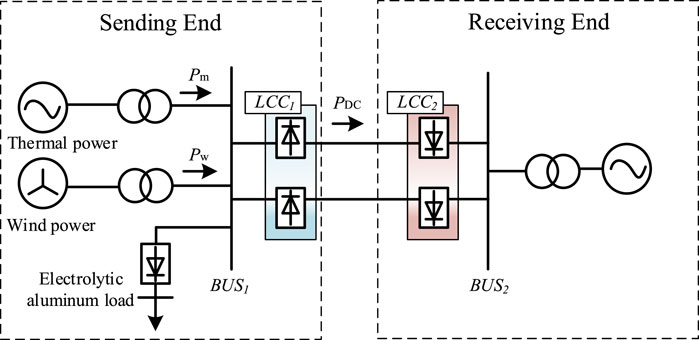
Figure 1. Structure of wind power unit with electrolytic aluminum load transmitted through the line-commutated converter high-voltage direct current (LCC-HVDC) system.
As shown in Figure 1, during stable operation, the active power of the sending-end system maintains equilibrium that can be expressed as Equation 1
Considering the primary frequency regulation of the system, the system frequency deviation
It is seen from Equation 2 that when there is a disturbance in the system, the system frequency deviation is closely related to the system inertia. However, for the system in which large-scale new energy bases are transmitted through UHVDC links, the inertia of the sending-end system is low, and a small power disturbance will cause a large fluctuation in the system frequency. When the frequency deviation caused by the system load disturbance is within the primary frequency regulation range of the synchronous units, the system operates stably. However, once the system load disturbance exceeds the limit of the primary frequency regulation adjustment of the synchronous units, it will be difficult for the synchronous units to suppress the frequency fluctuations caused by the unbalanced power; thus, the system frequency will decrease rapidly and seriously threaten the system security (Li et al., 2024). At this time, relying only on the synchronous units to achieve frequency regulation no longer meets the demand for frequency stability. Hence, it is necessary to further introduce the sending-end electrolytic aluminum load and UHVDC transmission system for coordinated frequency regulation.
2.2 Model of the electrolytic aluminum load
The grid connection diagram of the rectification equipment for electrolytic aluminum is shown in Figure 2. By utilizing the rapid adjustment characteristics of thyristors, electrolytic aluminum can quickly regulate the active power of the electrolytic aluminum series according to the frequency regulation requirements, achieving a reduction of 0%–40% of the rated load and an increase of 0%–10% of the rated load within approximately 80 ms (Xu et al., 2014; Du et al., 2023).
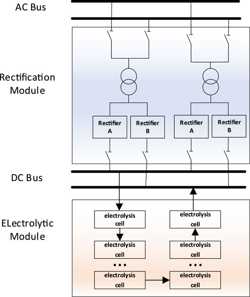
Figure 2. Schematic diagram showing the grid connection of rectification equipment for the electrolytic aluminum load.
The active power consumption of the
The structure of the rectifier controller in the electrolytic aluminum load is shown in Figure 3. To eliminate the influences of external disturbances on
3 Frequency control strategy for the UHVDC sending-end system with electrolytic aluminum load
3.1 Overall control structure
The frequency control structure of the UHVDC sending-end system with electrolytic aluminum load is divided into the upper and lower layers. The overall control structure is shown in Figure 4.
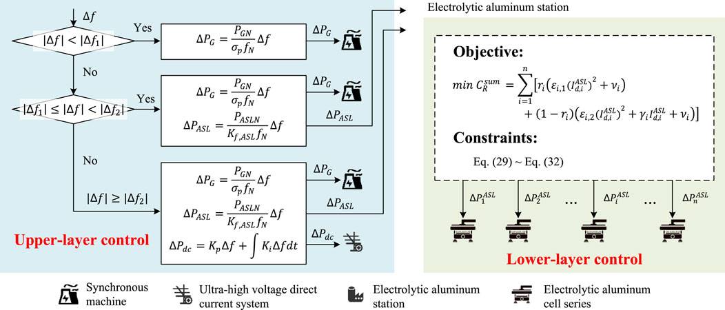
Figure 4. Overall control structure of the sending-end ultrahigh-voltage direct current (UHVDC) system.
3.1.1 Upper-layer control
The upper layer is mainly focused on coordinating the synchronous machine, electrolytic aluminum station, and UHVDC system. Specifically, it determines the frequency regulation power allocation for the synchronous machines, electrolytic aluminum loads, and UHVDC system based on the magnitude of the frequency deviation. When
3.1.2 Lower-layer control
The lower layer is mainly focused on coordinating the electrolytic aluminum cell series within the electrolytic aluminum station. Once the electrolytic aluminum station receives the command from the upper-layer control, the lower-layer control distributes the required regulation power to the individual electrolytic aluminum cell series by solving an optimization problem. This optimization considers the production state and control costs, including the production cost from output reduction and electrical energy cost during the heat preservation state when production is suspended. The lower-layer control must also meet the total regulated power constraint while ensuring that the combined regulation power of all cell series remains within their allowable limits. It also fine-tunes the self-saturable reactor to adjust the series current, maintaining it within the reactor’s voltage regulation capacity and minimum current limit.
3.2 Upper-layer source–grid–load coordinated control strategy
Frequent participation of the electrolytic aluminum load in system frequency regulation over a long period of time has a certain impact on the production efficiency of the high-energy-consuming load. Similarly, the power regulation of the UHVDC system also directly affects the power balance of the receiving-end power grid. Therefore, it is necessary to limit the ranges of participation of the electrolytic aluminum load and UHVDC system in frequency regulation to reduce the impacts of power disturbances on the loads and receiving-end power grid. Considering that different degrees of disturbance can lead to different amounts of unbalanced power, we divided the frequency support requirements into three scenarios based on the maximum reserve capacity and unbalanced power of the primary frequency regulation of the sending-end AC system.
Case 1. The power disturbance is small, and the absolute frequency deviation
Case 2. The absolute frequency deviation
Case 3. The absolute frequency deviation
It can be seen that the dead zone values
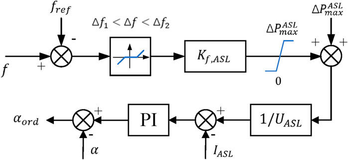
3.2.1 Structure and parameter settings of the electrolytic aluminum load participating in primary frequency control
When the absolute frequency deviation
Here, the frequency regulation of the dead zone value
When the absolute frequency deviation
Then, the relationship between the regulation amount of the electrolytic aluminum load and system frequency deviation can be expressed as
The power regulation undertaken by the electrolytic aluminum load is expressed as
By substituting Equations 8, 9 into Equation 10, the droop control coefficient of the electrolytic aluminum load can be obtained as Equation 11
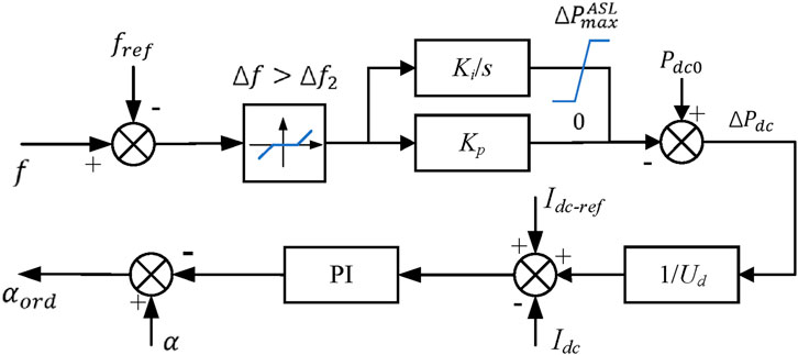
3.2.2 Parameter settings of the frequency regulation dead zone for the UHVDC system
When the absolute frequency deviation
The electrolytic aluminum station monitors the voltage, current, and power levels of the electrolytic series in real time. Based on the depth of voltage regulation of the self-saturated reactor equipped in the electrolytic series and current power level of the electrolytic series, the available active capacity of the
Combined with the reserve capacity of the primary frequency regulation of the synchronous generation unit, the dead zone parameter of the frequency regulation action of the UHVDC system is obtained as Equation 15
When the frequency deviation is greater than the dead zone value of frequency regulation
When the frequency change is greater than the dead zone value of frequency regulation
3.3 Decentralized frequency response strategy of the electrolysis cell
Once the electrolytic aluminum station receives the upper-layer control command
3.3.1 Modeling the control cost of the electrolytic aluminum load
The direct current series current value
Under production reduction, the series current
If the power consumed by the electrolytic aluminum load changes in response to frequency deviation, the production state will inevitably be affected. Compared to the normal production state of the electrolytic aluminum load, the economic loss caused by regulation due to the frequency response is the control cost and will be quantitatively analyzed.
Considering that a lengthy period of load reduction causes electrolyte cooling (8 h in summer and 4 h in winter), the duration of primary frequency regulation is relatively short. Therefore, the cost of damage to the electrolytic cell from maintaining electrolyte cooling for a long time can be ignored. Based on the different production states of the electrolytic aluminum load, the source of the control cost
Production cost
Electrical energy cost
Thus,
The relationship between the primary aluminum output and DC series current value can be expressed as Equation 18
To facilitate analysis of the piecewise function in Equation 17, the flag bit
By substituting Equation 19 in Equation 17, we obtain
By substituting Equations 20, 21 in Equation 17, the control load cost of the electrolytic aluminum series can be obtained as
The control cost of the entire electrolytic aluminum station is the sum of the control costs of the
3.3.2 Power distribution control strategy for the electrolytic aluminum series
Considering the form of
where
The expression of
The model also needs to satisfy the total regulated power constraint, which can be expressed as Equations 30, 31
Steady current control of the electrolytic series is achieved by fine-tuning the self-saturable reactor. Owing to the limited depth of voltage regulation of the self-saturable reactor, there are minimum values for both the voltage and series current of the electrolytic aluminum series. Therefore, the set series current should not exceed the voltage regulation capacity of the self-saturable reactor as shown in Equation 32:
The above model is a mixed-integer quadratic programming problem. In each dispatch control cycle, the power adjustment sequence for each electrolytic aluminum series is calculated through optimization and distributed to the lower-layer electrolytic series
4 Case study
4.1 Simulation design
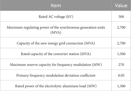
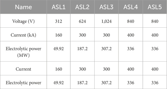
To verify the effectiveness of the abovementioned frequency regulation strategy, the UHVDC transmission system model with electrolytic aluminum load shown in Figure 1 was built and simulated in MATLAB/Simulink. The relevant simulation parameters are shown in Table 1. Among these, the load at the electrolytic aluminum station contains five electrolytic series ASL1–ASL5, all of which have the same type of self-saturable reactor with a voltage regulation depth of 70 V. The equipment parameters are shown in Table 2.
4.2 Source–grid–load coordinated frequency control experiment
In the simulations, two working conditions corresponding to frequency rise and frequency drop were set, and the dynamic response curves of the system frequency under participation or non-participation of the electrolytic aluminum load in the source–grid–load coordinated regulation were compared and analyzed to highlight the effectiveness and advantages of the proposed control strategy.
Condition 1: A wind farm failure occurs, resulting in a 450-MW power shortage in the system that causes the frequency of the sending-end power grid to drop.
Condition 2: A monopolar blocking fault occurs in the DC line, resulting in a 400-MW power surplus in the system that causes the frequency of the sending-end power grid to rise.
4.2.1 Simulation results under Condition 1
A 450-MW wind turbine generator was disconnected at
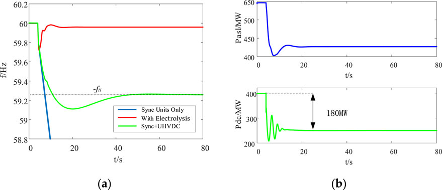
Figure 7. Simulation results under Condition 1 showing (A) a comparison of the effects of different frequency modulation methods and (B) the power consumed by the electrolytic aluminum station or delivered by the UHVDC grid.
As shown in Figure 7A, when only the synchronous units participate in frequency regulation without the electrolytic aluminum load or UHVDC system, the primary frequency regulation capacity of the synchronous generator units is maximum but still insufficient to compensate the unbalanced power of the system, eventually leading to rapid decline of the system frequency and to system collapse. As shown in Figure 7A, when the synchronous units and UHVDC system participate in frequency regulation, the final frequency will be stabilized near the frequency dead zone value of the UHVDC system. As seen in Figure 7B, during the adjustment process, there was a large power fluctuation in the receiving-end power grid; after reaching the steady state, the UHVDC system had a power transmission reduction of 180 MW that accounted for nearly 20% of the transmission capacity of the DC system and greatly reduced its utilization rate. In addition, although this scheme can suppress the frequency drop of the system, the frequency difference at steady state is large and there is much room for improvement.
As seen in Figure 7A, when the electrolytic aluminum load participates in grid frequency support through the source–grid–load fixed-value coordination strategy proposed in this paper, the power shortage reaches the action threshold of the electrolytic aluminum load that then participates immediately in the system frequency regulation control strategy. As seen in Figure 7B, under the proposed control strategy, the electrolytic aluminum station responds quickly to the frequency change and reduces the power of the entire station to that required by the dispatch control center within 2 s. Compared with the frequency regulation achieved with the control schemes of the participating units and UHVDC system, the proposed method increases the lowest point of frequency drop by 0.7 Hz. At the same time, compared with the UHVDC frequency regulation scheme, the frequency adjustment time of this strategy is significantly shorter, which has substantial advantages.
4.2.2 Simulation results under Condition 2
At
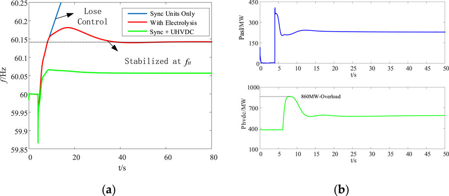
Figure 8. Simulation results under Condition 2 showing (A) a comparison of the effects of different frequency modulation methods and (B) power consumed by the electrolytic aluminum station or delivered by the UHVDC grid.
As shown in Figure 8B, when the electrolytic aluminum load participates in frequency regulation, the system power shortage reaches the action threshold of the electrolytic aluminum load that then immediately participates in system frequency modulation control and achieves rapid suppression of the frequency fluctuations within 20 s. At this time, the UHVDC line will have not reached the frequency action threshold yet and the transmission power remains unchanged, ensuring safe operation of the DC line. In addition, as shown in Figure 8A, the adjustment time, overshoot, and steady-state frequency difference of the proposed strategy have significant advantages compared to the frequency modulation scheme of the DC grid alone.
To further explore the influence of the participation degree of the electrolytic aluminum station in frequency modulation on the dynamic performance indicators of the system and operating process of the DC line, the processes causing frequency variations under different participation degrees of the electrolytic aluminum load in frequency modulation (100%, 90%, and 80%) were compared; these results are shown in Figure 9. As the participation degree of the electrolytic aluminum load in frequency modulation decreases, the system response speed gradually decreases, maximum point of frequency drop gradually decreases, and steady-state frequency difference gradually increases.
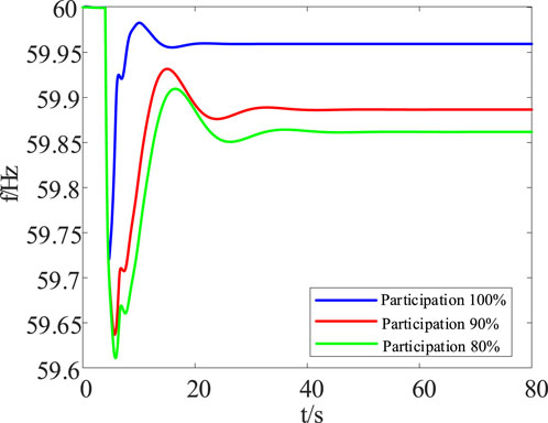
Figure 9. Comparison of the effects of the frequency adjustment process under different participation degrees of the electrolytic aluminum load.
By comparing the frequency variation curves of the DC grid participating in frequency modulation in Figures 8A, 9, it is understood that higher degrees of participation of the electrolytic aluminum load in frequency modulation result in lower adjustment power from the DC grid; moreover, both the dynamic and steady-state system performances are improved, fully demonstrating the superiority of the proposed method. With increase in the coordination degree of the electrolytic aluminum load, the system frequency can be quickly adjusted to the steady-state frequency with a small overshoot, thereby avoiding changes in the transmission power during the operation of the UHVDC line and effectively avoiding overload in the UHVDC grid while greatly improving the safety and reliability of the system.
4.3 Control cost analysis of the electrolytic aluminum station
To verify the effectiveness of the proposed optimal control strategy in reducing the control cost of the electrolytic aluminum load, a contrastive method of proportional dispatch is designed. This scheme dispatches the required frequency regulation power proportionally among all operating generators based on their available regulation power, which can be expressed as Equation 33
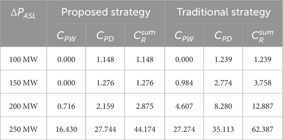
The profit of each ton of primary aluminum is set at 71.4 $/MWh here, and the electricity fee is 57.1 $/MWh. By setting
According to the results in Table 3, the proposed method shows superior performance in reducing the control cost of the electrolytic aluminum load. When
5 Conclusion
This paper presents a source–grid–load coordinated control strategy for the participation of electrolytic aluminum in frequency regulation at the DC sending-end grid. The proposed method effectively enhances system stability and reduces control costs. Simulation results confirm that this method significantly improves both the dynamic and steady-state performances of the power system. By leveraging the rapid response capabilities of electrolytic aluminum loads and the UHVDC system, the proposed strategy ensures efficient frequency regulation, minimizes power fluctuations, and prevents overload conditions. Additionally, the proposed method consistently demonstrates lower control costs compared to traditional proportional dispatch methods, particularly at higher regulation power levels. Thus, the proposed strategy offers substantial economic and operational benefits, underscoring its viability for practical applications in power system frequency regulation.
Data availability statement
The original contributions presented in the study are included in the article/supplementary material; further inquiries can be directed to the corresponding author.
Author contributions
CX: conceptualization, methodology, and writing–original draft. XX: conceptualization, formal analysis, and writing–original draft. XH: formal analysis, investigation, validation, and writing–review and editing. CD: formal analysis, supervision, and writing–review and editing. MZ: resources, visualization, and writing–review and editing.
Funding
The authors declare that no financial support was received for the research, authorship, and/or publication of this article.
Conflict of interest
Authors CX, XX, XH, CD, and MZ were employed by the Electric Power Research Institute of Yunnan Power Grid Co., Ltd.
Publisher’s note
All claims expressed in this article are solely those of the authors and do not necessarily represent those of their affiliated organizations, or those of the publisher, the editors, and the reviewers. Any product that may be evaluated in this article, or claim that may be made by its manufacturer, is not guaranteed or endorsed by the publisher.
References
Bao, P. (2021). Coordinated active power/frequency control from supply, network, and demand sides considering participation of aluminum smelter load. Shandong University. doi:10.27272/d.cnki.gshdu.2021.003789
Bao, P., Zhang, W., Cheng, D., and Liu, M. (2020). Hierarchical control of aluminum smelter loads for primary frequency support considering control cost. Int. J. Electr. Power Energy Syst. 122, 106202. doi:10.1016/j.ijepes.2020.106202
Bao, P., Zhang, W., and Zhang, Y. (2022). Secondary frequency control considering optimized power support from virtual power plant containing aluminum smelter loads through VSC-HVDC link. J. Mod. Power Syst. Clean Energy 11, 355–367. doi:10.35833/mpce.2021.000072
Du, S., Han, S., Xu, L., Huang, Y., Wang, K., Zhang, Z., et al. (2023). Load frequency stabilization control and parameter optimization method in isolated electrolytic aluminum industrial microgrid. IEEE Power Energy Soc. General Meet. 11, 616–621. doi:10.1109/PSGEC58411.2023.10255878
Guo, X., Zhang, J., Kang, P., Yang, G., Sun, Y., Yuan, T., et al. (2022). Virtual synchronization control strategy for UHVDC with secondary frequency modulation based on PI control. Electr. Power 55, 66–72. doi:10.11930/j.issn.1004-9649.202105025
Han, J., and Chen, Z. (2024). An inertial control method for large-scale wind farm based on hierarchical distributed hybrid deep-reinforcement learning. J. Clean. Prod. 450, 142034. doi:10.1016/j.jclepro.2024.142034
Han, J., Lyu, W., Song, H., Qu, Y., Wu, Z., Zhang, X., et al. (2023). Optimization of communication network for distributed control of wind farm equipped with energy storages. IEEE Trans. Sustain. Energy 14, 1933–1949. doi:10.1109/TSTE.2023.3264656
Han, J., Miao, S., Chen, Z., Liu, Z., Li, Y., Yang, W., et al. (2021). Multi-view clustering and discrete consensus based tri-level coordinated control of wind farm and adiabatic compressed air energy storage for providing frequency regulation service. Appl. Energy 304, 117910. doi:10.1016/j.apenergy.2021.117910
Li, C., Zhang, D., Han, J., Tian, C., Xie, L., Wang, C., et al. (2024). A multi-level operation method for improving the resilience of power systems under extreme weather through preventive control and a virtual oscillator. Sensors 24, 1812. doi:10.3390/s24061812
Li, J., Wang, B., Liu, C. Z., Wang, Y, Hu, X, and Han, L (2019). Suppression scheme for ultra-low frequency oscillation based on frequency limit controller. High. Volt. Eng. 45, 2126–2133. doi:10.13336/j.1003-6520.hve.20180822011
Luo, Z., Gao, P., Nie, L., Tian, X., Shen, X., and Zhang, Z. (2023). Research on cooperative frequency control strategy of wind-aluminum combined system. Electr. Mach. Control Appl. 50, 49–57. doi:10.12177/emca.2023.035
Mo, L., Lan, J., Zhou, L., Ye, M., Ma, L., and Chen, H. (2024). Multi-timescale frequency modulation control for flexible resources in virtual power plant. Automation Electr. Power Syst., 1–16. doi:10.7500/AEPS20230912004
Nie, S., Huang, R., Chen, L., Min, Y., You, G., and Wu, C. (2024). Adaptive control of primary frequency regulation for electrolytic aluminum considering energy recovery. Automation Electr. Power Syst. 1, 13. doi:10.7500/AEPS20230821009
Wang, C., Han, J., Jiang, D., Zhang, W., Yang, W., Song, H., et al. (2024a). Research on autonomous operation and mutual aid strategy of AC/DC hybrid microgrid cluster. Electr. Power Syst. Res. 231, 110302. doi:10.1016/j.epsr.2024.110302
Wang, G., Shi, R., Cheng, W., Gao, L., and Huang, X. (2023). Bibliometric analysis for carbon neutrality with hotspots, frontiers, and emerging trends between 1991 and 2022. Int. J. Environ. Res. Public Health 20, 926. doi:10.3390/ijerph20020926
Wang, H., Han, J., Jiang, D., Zhang, W., Yang, W., Song, H., et al. (2024b). Large signal stability control method of DC microgrid with analogous virtual synchronous generator and flexible load. Trans. China Electrotech. Soc. 1, 13.
Wang, Y., Zhu, J., Zeng, Q., Tai, K., Yu, G., Yin, A., et al. (2022). Multi-objective bi-level optimization design method of DC frequency limiting controller parameters. Electr. Power Autom. Equip. 42, 189–196+224. doi:10.16081/j.epae.202205035
Xin, Y., Zhang, J., Jiang, S., Wang, W., and Wang, T. (2023). Coordinated control strategy to improve frequency stability at sending terminal of ultra-high voltage direct current transmission system. Power Syst. Technol. 47, 5089–5097. doi:10.13335/j.1000-3673.pst.2022.2099
Xu, J., Liao, S., Sun, Y., Ma, X., Gao, W., Li, X., et al. (2014). An isolated industrial power system driven by wind-coal power for aluminum productions: a case study of frequency control. IEEE Trans. Power Syst. 32, 22080. doi:10.1109/PESGM.2015.7286407
Yang, W., Miao, S., Liu, Z., Han, J., Xiong, Y., and Tu, Q. (2021). Model predictive direct power control of grid-connected converters considering unbalanced filter inductance and grid conditions. J. Mod. Power Syst. Clean Energy 9, 1279–1288. doi:10.35833/MPCE.2021.000355
Yang, Y., Yan, F., Yang, Y., and Chen, Y. (2023). Evaluating provincial carbon emission characteristics under China’s carbon peaking and carbon neutrality goals. Ecol. Indic. 151, 111146. doi:10.1016/j.ecolind.2023.111146
Yang, Z., Han, J., Wang, C., Li, L., Li, M., Yang, F., et al. (2023). Emergency power supply restoration strategy for distribution network considering support of microgrids with high-dimensional dynamic correlations. Electronics 12, 3246. doi:10.3390/electronics12153246
You, G., Li, L., and Zhu, X. (2018). Analysis on adaptability of Yunnan power grid to wudongde multi-terminal DC. Guangdong Electric Power 31 (09), 32–38.
Zhang, X., Liu, F., Wang, S. B., and Li, Y. (2022). “Measures to improve the new energy consumption level of UHVDC sending-end power gird,” in Proceedings of the CSU - EPSA 2022 34 (06), 135–141. doi:10.19635/j.cnki.csu-epsa.000914
Nomenclature
Abbreviations
UHVDC ultrahigh-voltage direct current
FLC frequency limit controller
DC direct current
AC alternating current
DR distributed resources
VSC-HVDC voltage source converter high-voltage direct current
LCC-HVDC line-commutated converter high-voltage direct current
LCC line-commutated converter
ASL aluminum smelting line
PI proportional–integral
PWM pulse-width modulation
Frequency response model
LCC1 rectifier station connecting the sending-end system including the wind farm, synchronous units, and electrolytic aluminum load
Bus1 bus of the alternating current system on the rectifier side
Rd1 resistance of the direct current line
LCC2 inverter station connecting the receiving-end alternating current power grid
Bus2 bus of the alternating current system on the inverter side
Pm output of the synchronous unit
Pw output of the wind turbine unit
PLD1 load power of the sending-end system
PASL power of the electrolytic aluminum load
Pdc transmission power of the high-voltage direct current line
PG total generated output of the sending-end system
PL total active load demand of the sending-end system
Hsys equivalent inertia of the sending-end power grid
ΔPG active power of the primary frequency regulation response of the sending-end power grid
ΔPL variation in the active load
D damping coefficient of the sending-end power grid
Δf frequency deviation of the sending-end power grid
f actual frequency of the sending-end power grid
f0 rated frequency (50 Hz)
PiASL active power consumption of the ith electrolysis cell
UiASL voltage of the ith electrolysis cell
IiASL current of the ith electrolysis cell
Iref, iASL reference value of the current of the ith electrolysis cell
Frequency control strategy
|Δf| absolute frequency deviation
|Δf1|, |Δf2| dead zone values of the frequency regulation
σp droop coefficient of the primary frequency regulation of the synchronous generation units
PGmax maximum regulating power of the synchronous generation units
ɑ initial control angle of the converter
ɑord command control angle of the converter
PGN rated power of the generation unit
PASLN rated power of the electrolysis cell
Kf,ASL frequency droop coefficient of the electrolytic aluminum load
ΔPASL power deviation of the electrolytic aluminum station
ΔPunb power disturbance generated by the system
ΔPmax,iASL available active capacity of the ith electrolytic aluminum series
Umax, iASL maximum voltage of the ith electrolytic aluminum series
Imax, iASL maximum current of the ith electrolytic aluminum series
ΔPmaxASL available active capacity of the entire electrolytic aluminum station
Kp coefficients of the proportional links
Ki coefficients of the integral links
ΔPmax upper limit of the power adjustment amount
ΔPdc0 reference value of the transmission power of the high-voltage direct current line
ΔPdc transmission power value of the high-voltage direct current line after adjustment
IiASL direct current series current value
Ii,0ASL rated value of the direct current series current
CR source of the control cost
CPD production cost
CPW electrical energy cost
CR,I control cost of the ith electrolytic series
M0,I output of the primary aluminum under normal production conditions
MR,I output of the primary aluminum after load reduction or increase
cprft profit of the primary aluminum per unit output
cfree unit electricity cost
ŋ0,I rated current efficiency in the ith electrolytic series
ri flag bit
εi,γi,νi coefficients of the piecewise quadratic function
PiASL active power that the ith electrolytic series must generate
Pavail, iASL available reactive power of the ith electrolytic aluminum series at a specific moment
Rsum total cost
Keywords: frequency regulation, ultrahigh-voltage DC system, electrolytic aluminum load, source–grid–load control strategy, hierarchical control
Citation: Xing C, Xi X, He X, Deng C and Zhang M (2024) Collaborative source–grid–load frequency regulation strategy for DC sending-end power grid considering electrolytic aluminum participation. Front. Energy Res. 12:1486319. doi: 10.3389/fenrg.2024.1486319
Received: 26 August 2024; Accepted: 28 October 2024;
Published: 27 November 2024.
Edited by:
Rui Wang, Northeastern University, ChinaReviewed by:
Wentao Jiang, Northwestern Polytechnical University, ChinaBingyu Wang, North China Electric Power University, China
Copyright © 2024 Xing, Xi, He, Deng and Zhang. This is an open-access article distributed under the terms of the Creative Commons Attribution License (CC BY). The use, distribution or reproduction in other forums is permitted, provided the original author(s) and the copyright owner(s) are credited and that the original publication in this journal is cited, in accordance with accepted academic practice. No use, distribution or reproduction is permitted which does not comply with these terms.
*Correspondence: Chao Xing, eGluZ2NoYW9feW5kd0AxMjYuY29t
 Chao Xing
 Xinze Xi
