- 1L2EI Laboratory, Jijel University, Jijel, Algeria
- 2College of Computer and Information Sciences, Prince Sultan University, Riyadh, Saudi Arabia
- 3Automated Systems and Soft Computing Lab (ASSCL), Prince Sultan University, Riyadh, Saudi Arabia
- 4Faculty of Computers and Artificial Intelligence, Benha University, Benha, Egypt
Controlling variable wind speed turbine (VWT) system based on a doubly-fed induction generator (DFIG) is a challenging task. It requires a control law that is both adaptable and robust enough to handle the complex dynamics of the closed control loop system. Sliding mode control (SMC) is a robust control technology that has shown good performance when employed as a passive fault-tolerant control for wind energy systems. To improve the closed control loop of VWT based on DFIG with the aim of improving energy efficiency, even in presence of nonlinearities and a certain range of bounded parametric uncertainties, whether electrically or mechanically, an adaptive passive fault tolerant control (AP-FTC) based on a self-tuning fractional integral sliding mode control law (ST-FISMC) developed from a novel hyperbolic fractional surface is proposed in this paper. ST-FISMC introduces a nonlinear hyperbolic function into the sliding manifold for self-tuning adaptation of control law, while fractional integral of the control law smooths discontinuous sign function to reduce chattering. Additionally, this work introduces an adaptive observer, developed and proved based on a chosen Lyapunov function. This observer is designed to estimate variations in electrical parameters and stator flux, ensuring sensorless decoupling in indirect field- oriented control (SI-FOC) of DFIG. Lyapunov theory is also used to prove stability of states vectors in closed control loop with presence of bounded parameters uncertainties or external disturbances. Simulation results show that the proposed approach offers better performance in capturing optimal wind energy, as well as the ability to regulate active/reactive power and high resilience in presence of occurring parameter uncertainties or external disturbances.
1 Introduction
The demand for electrical energy is increasing worldwide due to its essential role in modern-day living. It is necessary for economic, social, and industrial development in all countries globally, serving as a key indicator used to measure development gaps between regions. As a result, global electricity consumption reached 25,530 TWh by 2022 (Ammar et al., 2019). This increasing demand presents a significant challenge for sustainable development while raising concerns about the depletion and ecological impact of traditional fossil fuels like petroleum, natural gas, and coal, which have been the primary sources for electricity production.
To address these concerns, many countries are exploring clean and renewable energy sources to meet their energy needs (Meghni et al., 2017; Kamal and Ibrahim, 2018). Among these options, wind energy has emerged as a particularly promising choice (Durgam et al., 2022; Dhanraj et al., 2022a; Dhanraj et al., 2022b; Abdelrahim and Almakhles, 2023; Jaikrishna et al., 2023; Sethi et al., 2023; Kesavan et al., 2024). As a result, the installation of wind energy systems has experienced significant growth, especially over the last decade (Saha et al., 2022). The total installed wind energy capacity in the world increased from 31 GW in 2002 to 283 GW in 2012, reaching a final statistic of 906 GW by the end of 2022 (Global Electricity Consumption, 2022; Global Wind Energy Council, 2022).
Wind power conversion system is based on converting a portion of kinetic energy extracted from wind into electrical energy using a generator. There are two main types of wind turbines based on their mode of operation: fixed-speed wind turbines and variable-speed wind turbines. Currently, variable-speed wind turbines are the most commonly used type due to their numerous advantages over fixed-speed wind turbines. These advantages include a reduction in stress on mechanical structure, reduced acoustic noise, and provide ability to directly control active and reactive power (Mazare, 2024).
Variable wind speed turbines (VWT) require a generator that operates at variable speed, such as doubly fed induction generator (DFIG). This technology has gained popularity due to its cost-effectiveness, simple structure, robustness, and high energy efficiency (Benbouhenni et al., 2024). It enables variable-speed operation within a range of approximately ±30% around the synchronous speed, leading to lower converter costs, reduced power losses, and complete control over active and reactive power (Eskandari et al., 2023).
Despite advantages of VWT the fluctuating nature of wind introduces external disturbances that can cause deviation overactive operating point of DFIG (Gao et al., 2024). Consequently, this has the potential to result in electrical or mechanical failures in wind power conversion system (Jiang et al., 2024), affecting its overall performance and reliability (Mechter et al., 2016). It’s worth noting that approximately 18% of wind turbine failures are attributed to generator issues (Kamarzarrin et al., 2022). Therefore, numerous studies have been conducted to enhance the closed control loop of wind power conversion systems and improve their power production performance (Majout et al., 2024). Proportional-integral (PI) control law has been extensively integrated into the rotor side converter control (RSC) in various studies (Azar and Serrano, 2015; AL-Wesabi et al., 2024; Kalel and Raja Singh, 2024). However, in spite of their relative ease of implementation, these methods are not highly effective in efficiently controlling faulty wind power conversion systems. As a result, researchers have developed various control methods based on more efficient and robust modern control techniques, implementing them using different strategies to enhance the performance of wind power conversion systems. These include intelligent control methods such as fuzzy logic control (Dida et al., 2020; Chakraborty and Maity, 2023), neuronal control (Mahmoud et al., 2016; Ponce et al., 2018; Naresh et al., 2020; Benbouhenni et al., 2024), predictive control (Messadi et al., 2015; Messadi and Mellit, 2017; Takhi et al., 2022), and adaptive control (Bhattarai et al., 2016; Lin et al., 2018; Yuan et al., 2018).
Fault tolerant control (FTC) is a commonly employed strategy for controlling faulty systems, aiming to ensure system availability and reliability while maintaining stability and precision. There are two main types of FTC: active and passive.
Active FTC involves designating a dynamic block for fault detection and isolation (FDI), followed by reconfiguring the control law to correct the system in response to detected faults. Various control schemes have been proposed, such as an augmented observer-based approach (Wang and Shen, 2019) and a linear parameter variant (LPV) approach (Shi and Patton, 2015) for fault detection in offshore wind turbine models. Additionally, a nonlinear observer has been developed for sensor fault detection and diagnosis (Xiahou et al., 2019). Intelligent fault-tolerant control methods have been also employed, such as extreme learning machines for online monitoring (Abdelmalek et al., 2018), and development of fuzzy Takagi-Sugeno observers. A comprehensive review of fault detection and isolation schemes in wind turbines can be found in Saha and Singh (2019).
On the other hand, passive fault-tolerant control does not require fault detection or reconfiguration of the control law. It involves applying a single control law, typically based on robust control methods to both healthy and faulty systems (Djeghali et al., 2013). For instance, Mechter et al. (2016) proposed backstepping control for wind turbine with an uncertain DFIG. Bossoufi et al. (2014) developed a robust adaptive backstepping control approach, Reddak et al. (2016) introduced a new integral backstepping control, and robust H∞ method was used in Bakou et al. (2019) for fault-tolerant control of wind turbines.
In addition to the above-mentioned methods, sliding mode control (SMC) is a well-known passive FTC method, it has been widely used for its simplicity of implementation and robustness against parameter variations, external disturbances, as well as high coupling and nonlinear dynamic controlled system. Despite its simplicity, SMC can effectively handle sophisticated higher-order nonlinear dynamics by controlling a first-order system rather than an nth order system (Singh et al., 2017).
The concept of SMC was initially proposed by Russian mathematician Vladimir V. Emelyanov in the 1960s as part of the theory of variable structure systems (Emelyanov, 1967). Subsequently, Russian mathematician, Vadim Utkin, developed a modern formulation of SMC in the late 1970s and early 1980s (Poznyak and Orlov, 2023). Since then, SMC has been extensively studied and developed by researchers and has found applications in various engineering domains such as aerospace (Hace, 2019), automotive, including electric vehicles, hybrid vehicles, and autonomous vehicles (Saadaoui and Ouassaid, 2024). It has also been used in stabilization and synchronization of chaotic systems (Zhang et al., 2022), chemical processes (Vásquez et al., 2023), and biomedical engineering (Ahmad et al., 2017). SMC has proven to be efficient when applied in the field of renewable energy, particularly in controlling both mechanical and electrical components of variable wind power conversion systems (Zholtayev et al., 2022).
In SMC, the key concepts of attractivity, equivalent control, and dynamics are employed to achieve the main objective of attracting the controlled system’s state variables toward a specific sliding manifold from any initial conditions. Once reaching motion is achieved, the system smoothly transitions into a sliding mode, where it dynamically slides along the sliding surface towards the desired equilibrium point. SMC technique ensures stability of system even in presence of disturbances. However, it’s important to note that sliding motion is achieved by using a discontinuous function, such as sign function in switching control law, which can lead to an undesirable phenomenon called chattering, especially at high frequencies.
To mitigate chattering, various solutions have been proposed in the literature, such as replacing sign function by saturation function or a tangent hyperbolic function to smooth the switching surface. Other approaches propose the use of adaptation gain in discontinuous control law, as well as the combination of intelligent control techniques, such as fuzzy logic control with sliding mode control (Eskandari et al., 2023). Sepestanaki et al. (2024) developed a new strategy that uses an adaptive continuous barrier function to remove chattering and steady-state error, and it has been successfully applied in the synchronization and stabilization of chaotic systems. In context of advanced control strategies, fractional calculus emerges as a prevalent strategy in control law synthesis for integer-order systems. It has gained wide adoption across various fields due to its ability to enhance stability and improve performance (Rabah and Ladaci, 2017).
This paper proposes an adaptive passive fault-tolerant control (AP-FTC) based on a new self-tuning fractional integral sliding mode control (ST-FISMC). The proposed approach has the following key contributions:
(a) Improve the closed control loop of the DFIG-based VWT to enhance energy efficiency, even with non-linearities and limited parameter uncertainties (electrical or mechanical).
(b) Automatically adapt the control law by adjusting the power rate and gain of a hyperbolic function. This enables the system to maintain stability when disturbances occur, using a non-linear terminal hyperbolic cosine function of the tracking error in the sliding surface.
(c) To further enhance stability and minimize undesired chattering, fractional derivatives and integrals are integrated into the control law synthesis, instead of relying solely on integer-order derivatives and integrals.
(d) An adaptive observer in the d-q (direct-quadrature) reference frame is used to estimate the stator flux, enabling sensorless decoupling in the sensorless indirect field-oriented control (I-FOC) to avoid using a flux sensor in the closed-loop feedback.
It is worth noting that the hyperbolic cosine function has already demonstrated its effectiveness in achieving self-tuning adaptation of gains in classical PID control (Mohan et al., 2018).
The paper is organized as follows: Section 2 presents proof of the proposed control law using Lyapunov theory for a general nonlinear uncertain system. Sections 3, 4 discuss mathematical modeling of both healthy and faulty VWT and DFIG. Based on the proposed approach, the control laws for mechanical rotational speed and stator active and reactive power of DFIG in d-q frame are developed in Section 5. Section 6 provides a proof of an adaptive observer and the estimation of electrical parameters using a chosen Lyapunov function. Simulation results and discussion are presented in Section 7. Finally, Section 8 concludes the paper.
2 Design of the proposed control law
2.1 Design of classical sliding mode control
Consider a nonlinear uncertain system described as follows:
where:
The goal is to design a robust control law that allows state vector to converge asymptotically to an equilibrium point from any initial condition within a finite time and sustain this convergence even in presence of bounded parameters uncertainties or disturbances. To achieve this, the paper chooses to use SMC due to its robustness and ease of implementation, where the conception of classical SMC law is mainly based on two steps.
Initially, the design of a sliding surface is required. According to a general law proposed by Slotine and Li (1991), the general form of sliding surface is described as follows in Equation 2:
where:
The second step consists of differentiating the chosen sliding surface and extracting SMC law expressed as follows in Equation 3:
where:
k is a positive constant called switching gain.
Even if this command has proven its effectiveness in terms of robustness, it must be noted that it has a major inconvenience called chattering. This issue is mainly attributed to the use of sign function, especially when increasing switching gain k to enhance stability in presence of bounded uncertainties or external disturbances. In response to this challenge, this paper proposes a robust self-tuning fractional integral sliding mode control (ST-FISMC). The aim is to mitigate chattering phenomenon and adeptly manage the impact of occurring bounded uncertainties.
2.2 Design of self-tuning fractional integral sliding mode control
2.2.1 Preliminaries on fractional calculus
There are several definitions in the literature on fractional calculus for the fundamental fractional operator
2.2.1.1 Riemann–Liouville (R-L)
R-L derivative and integration of order
With:
Where:
2.2.1.2 Caputo definition
Caputo’s fractional-order differentiation is defined by (Hu et al., 2008) in Equation 7:
Where:
Similarly, by Caputo’s definition, the integral is described as in Equation 8:
2.2.1.3 Oustaloup approximation
In order to use fundamental fractional operator several approximations to integer order transfer function were proposed, however in what follows we use Oustaloup filter approximation to approximate fractional-order differentiator integration (Monje et al., 2010). A generalized Oustaloup filter can be designed as in Equation 9:
where the detailed function MATLAB of Oustasloup filter can be found in (Monje et al., 2010).
Some proprieties of fractional order:
In order to prove the stability of the proposed fractional control law, we utilize the following proprieties (Monje et al., 2010):
- The operator of order α = 0, is the identity operator.
- The operator of order must be linear:
- For fractional-order integrals of arbitrary order,
2.2.2 Design of the proposed control law
Let us choose self-tuning terminal fractional sliding surface as follows:
where:
Fractional calculus has been chosen to improve the stability of closed control loop system, and to smoothly discontinues control law by using fractional integral of control law instead of integer integral of control. The goal is to vary the integration order of control law and consequently acting on discontinues control law by smoothing switching term such us sigmoid function, saturation function or others functions that can be used. Self-tuning adaptation of control law is ensured by using a hyperbolic cosine function in the equivalent control law. Its specific purpose is to reduce time reaching to the desired equilibrium point, even in the presence of bounded uncertainties or external disturbances.
Consider the following adaptive passive fractional integral sliding mode control law Based on sliding surface Equation 12:
Adaptive switching surface is chosen as follows:
where:
However, it must be noted that the proposed control law is robust against occurred faults when the following assumption are satisfied in Equations 15–19.
Assumption 1. Parameter uncertainties of uncertain nonlinear system and term of occurs external disturbances are supposed to be bounded, and the following inequalities must be satisfied:
where:
Note that the upper bounded of fractional derivatives of
Assumption 2. By defining the expression of the applied control law must be bounded, and the following inequalities must be hold:
It follows that fractional derivative of the control law will be bounded:
Assumption 3. Taking into account inequalities of Assumption 1 and Assumption 2, it follows that:
Theorem: consider uncertain nonlinear system Equation 1, given sliding surface Equation 12 and the fractional control law Equation 13, then the state vector x(t) will converge asymptotically to zero.
2.2.2.1 Stability proof
To prove stability of uncertain system Equation 1 using the proposed control law Equation 13, and to determine adaptive gain of discontinuous control law, let us consider the following positive candidate Lyapunov function in Equation 20:
Uncertain system Equation 1 will be stable if the following stability condition is satisfied in Equation 21:
Since
Taking the first derivative of candidate Lyapunov function than Equation 20 becomes in Equation 22:
By applying properties of fractional calculus, the first derivative of sliding surface Equation 12 can be obtained as follows:
Using proprieties given in Equations 10, 11 we get:
With:
By substituting Equation 29 in Equation 22 we obtain:
To satisfy stability condition Equation 21 the following conditions must be hold:
From Equations 23–35 and if we choose the parameters of switching surface
3 Modeling of wind power conversion system
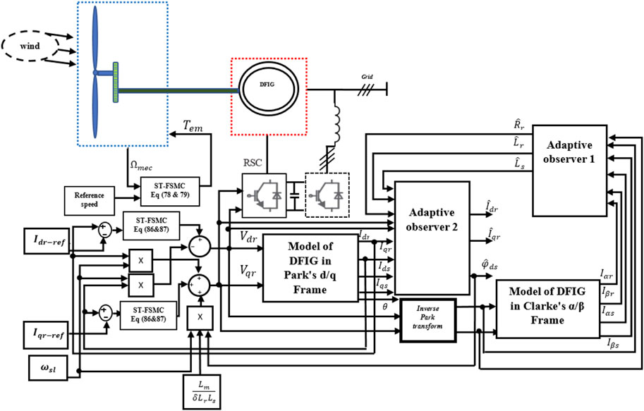
Wind power conversion system captures wind’s kinetic energy through blades, transforming it into mechanical energy via the drivetrain to achieve angular speed. The captured mechanical energy is then converted into electrical energy via a generator, such as DFIG used for the remainder of this study, as shown in Figure 1 (Mechter et al., 2015). However, both mechanical and electrical systems are subjected to nonlinearities due to the fluctuating nature of wind, which can lead to parameter variations in either mechanical or electrical components.
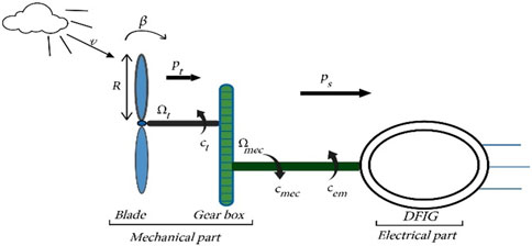
Figure 1. Schematic of DFIG based wind turbine system (Mechter et al., 2015).
This section presents mathematical modeling of wind turbine and DFIG in both healthy and faulty conditions. First, mathematical modeling of the studied system within balanced operational conditions will be discussed, assuming nominal parameters. Nonetheless, actual parameter variations during operation can trigger significant faults, efficiency fluctuations, and even system shutdown. To ensure system stability and performance, it's imperative to incorporate these parameter variations when crafting control laws. As a result, a comprehensive mathematical model of the studied system, specifically addressing faulty conditions while considering variations in parameters and occurred sensor faults, will be illustrate.
3.1 Modeling of wind turbine
3.1.1 Health condition
Upon the direct application of wind speed, denoted as
Where:
However, wind turbine cannot recover all the energy provided by wind. The aerodynamic power that can be generated from wind power, taking into account a power factor coefficient named
Where power coefficient
with:
β represents pitch angle. On the other hand, λ is the tip speed ratio it quantifies the relationship between linear speed at the blade tips and wind speed. It is defined as in Equation 40:
Given
Mechanical torque and rotational mechanical speed denoted by
By applying the fundamental equation of dynamic than rotational mechanical speed can be described as follows in Equation 43:
where:
3.1.2 Faulty condition
During the operation of wind power conversion system, several faults can occur at the mechanical level, such as breakage of gears surface, increase in gearbox oil temperature, bearing fault, offset in generator torque, sensor faults including generator speed, rotor speed and pitch angle sensor faults. Without forgetting actuator faults like pitch angle actuator faults, and variations in parameters such as the variation in the gap of power coefficient and tip speed ratio. These issues can impact the quality of mechanical power extracted from wind.
Assumption 4. When considering low wind speeds and Zone II operating conditions, the equation Equation 43 representing the dynamic of rotational mechanical speed for maximum power point tracking (MPPT) can be rewritten as follows (Mechter et al., 2015):
This section will be concerned about sensor faults in mechanical rotor speed and parameter variation of optimal speed ratio and maximum power rate coefficient, it follows that Equation 44 becomes:
Where y is the output measurement of rotational mechanical speed and
After simplification Equations 45, 47, 48 becomes:
4 Modeling of DFIG in stator field orientation
4.1 Healthy condition
Mathematical representation of T-equivalent circuits of DFIG in synchronous reference frame (d-q) is given by the following set of equation (Mechter et al., 2015) in Equation 48:
where:
Stator’s linkage fluxes in (d-q) axes are defined as in Equation 49:
Rotor’s linkage fluxes in (d-q) axes are defined as:
In addition to (d-q) representation, further simplification is employed, such as utilizing field-oriented control (FOC), to enhance control by aligning fluxes along the d or q axes. In the remainder of this work, stator flux is assumed to align with the d-axis maintained at a constant level
Considering simplifications mentioned above, stator currents in (d-q) reference frame, and stator fluxes will be expressed as follows in Equations 51, 52:
When the system reaches stability, the stator flux is expected to be constant. Consequently, its first derivative will be equal to zero. This leads to the first derivative of the (d-q) stator currents being as follows (Li et al., 2010) in Equation 53:
By replacing Equation 51 in Equation 50 than rotor’s fluxes in (d-q) frame become:
The first derivative of Equation 54 yields:
Where:
The substitution of Equations 54–57 into Equation 48c,d yields the following expression for the rotor voltage in (d-q) frame:
It follows, the steady-state representation of rotor currents in (d-q) frame:
The states equations representing DFIG are given in Equation 60:
Active and reactive powers at the stator side of DFIG are defined by in Equations 61, 62:
By replacing stator currents given in Equation 51, and taking into account simplification about stator voltages, then active and reactive powers at stator side of DFIG will be defined by in Equations 63, 64:
Note that due to constant stator voltage, stator active and reactive powers are controlled by means of
4.2 Faulty condition
During operation of wind power conversion system, 18% of failures are attributed to electrical components, which can cause considerable damage and increase shutdown time. DFIG faults considered in this paper include rotor resistance variation due to mechanical, environmental, and thermal factors such as rotor heating or broken rotor bars. Additionally, stator and rotor inductance variations are considered, primarily caused by electrical stresses such as stator and rotor winding insulation failures and inter-turn short circuits in stator windings.
Let us consider additional bounded unknown variations
By substituting Equation 65 in Equations 58, 59 the (d-q) torque currents equations becomes:
On the other hand (d-q) stator currents and d-stator flux are also affected by Equation 65 and their expression become:
After simplification and rearranging Equations 66, 67, the state space representation of DFIG can be written as follows in Equation 68:
Where state vector, and control input vector of DFIG are described as in Equation 69:
The nominal parts of smooth fields
Additionally faulty terms due to parameters variations
Uncertainty terms
In order to handle the above uncertainties terms, we use the proposed control law of this paper Equations 13, 14.
5 Rotor side converter control strategies
5.1 Rotational mechanical speed controller
Controlling rotational mechanical speed in variable wind turbine system is ensured via controlling electromagnetic torque
Let us consider the following switching surface in Equation 75:
The tracking error of rotational mechanical speed and its first derivative are given by in Equation 76:
By rewriting Equation 44 as follows Equations 77, 78:
where:
According to Equation 14 discontinuous control law is ensured and switching surface is given by in Equation 79:
5.2 Indirect control of DFIG
Controlling active and reactive power of DFIG is effectuated via
Let us consider currents errors to be as:
Taking the first derivative of Equation 80 it follows in Equation 81:
The sliding surfaces according to Equation 12 are given by:
In order to ensure indirect control of DFIG decoupling is achieved by eliminating electromagnetic force EMF and coupled currents terms, which are considered as perturbation as shown in bloc diagram Figure 2.
The (d-q) rotor steady states currents used for the conception of control laws
Taking the first derivative of Equation 82 we get Equation 84:
After simplification of Equation 85 fractional integral control laws of are given by the following Equation 86:
with:
According to Equation 14 discontinuous control law is ensured and switching surfaces are given by Equation 87:
Control laws are not applied directly to DFIG, instead FEM and coupled terms must be added to vector controller with opposite signs to their original terms in DFIG, thus ensuring decoupling and achieving an indirect control strategy.
6 Design of adaptive sliding mode observer
Applying passive fault-tolerant control law in closed control loop system doesn’t necessitate fault detection and isolation (FDI) block. However, estimating parameter variations or external perturbations that can impact on a system is essential to enhance its maintainability. Additionally, sensorless indirect control of DFIG is achieved through the estimation of stator flux. This section will provide proof of an adaptive sliding mode observer using Lyapunov candidate function. In order to avoid nonlinearities of rotational (d-q) reference frame of DFIG mainly caused by rotational speed in
Adaptive sliding mode observer using (
Where estimated parameters of DFIG are defined as follows:
With:
To prove the stability of currents observers, and to find parameter uncertainties estimation we use tow adaptive Lyapunov candidate function in what follows.
Let us consider positives Lyapunov candidates’ functions:
With:
The first derivative of errors mentioned above we get:
After simplification Equations 91, 92 become:
From Lyapunov stability theorem (Slotine and Li, 1991), the sliding-mode condition can be derived to satisfy stability condition Equation 21.
Taking the time derivative of Equation 90, we find:
Taking into account Equations 93, 94 than Equation 95 can be simplified to:
To satisfy Lyapunov condition
The second step for satisfying Equation 21 is to set remainders terms of Equation 96 to zero as follows:
After simplification of Equation 98 estimated parameter uncertainties can be described by the following Equation 99:
The faulty model of DFIG proposed in Section 4 was based on changes of nominal values
sigmoid function is replaced by tangent hyperbolic function denoted:
Taking into account faulty Equation 65 and estimated parameters Equation 100 adaptive stator flux observer is given by Equation 101:
Remark: note that adaptive observer was developed in the stationary reference frame (
7 Simulation results
To validate the efficiency and robustness of the proposed control law and adaptive observer simulation results issue from MATLAB/SIMULINK environment of variable wind speed turbine based doubly feed induction generator will be illustrated in this section. In order to simulate fractional systems in MATLAB SIMULINK, various toolboxes have been designed. In this paper, the “Ninteger” MATLAB toolbox (Valerio, 2005) has been used to simulate fractional order controllers.
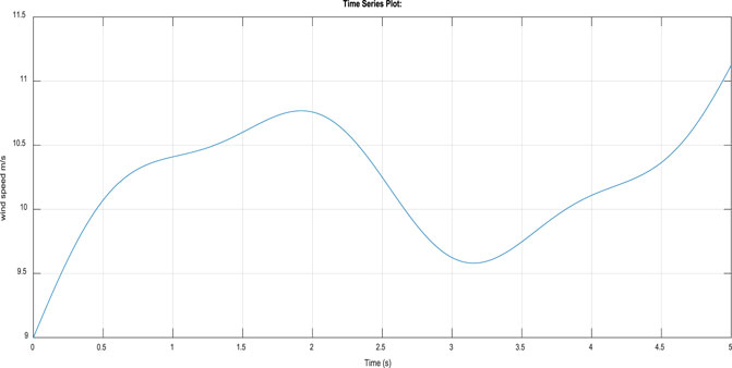
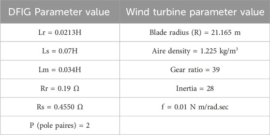
The profile of variable wind speed used for the simulation is shown in Figure 3. It represents low speed and varies around 12 m/s. The parameters of the wind turbine and DFIG used for the simulation are given in Table 1. The parameters of the control laws and the adaptive observer were chosen according to the stability conditions proved in Sections 2, 6 using Lyapunov theory. This section illustrates the simulation results of the proposed control law on the studied system in both healthy and faulty conditions. To demonstrate the efficiency of our approach, it is compared with The fractional sliding mode control (FSMC) proposed by (Penghan et al., 2020).
7.1 Case 1 healthy condition
This part shows the responses of states vector to a desired states using the proposed adaptive fractional sliding mode control law of this paper. In this case wind turbine and DFIG are supposed to be operating in healthy condition. The parameter of control law and observer are chosen as follows:
The fractional operator
7.2 Case 2 faulty condition
In this part we suppose that the parameter of DFIG are subjected to variations, and the mechanical rotational speed sensor is deflected due to unknown external disturbances.
Scenario1:
7.3 Discussion of simulation results
Simulation results were dedicated to showcasing the performance of our proposed control method on the studied system in both healthy and faulty scenarios. A brief discussion of the two cases will follow.
7.3.1 Case 1
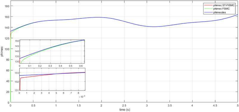
In the first case, our focus was on Variable Wind Turbine (VWT)-based Doubly Fed Induction Generator (DFIG) operating under healthy conditions. Figures 4, 5 illustrate the fast response of active and reactive power of DFIG to the desired values. The tracking error, depicted in Figure 6, was approximately
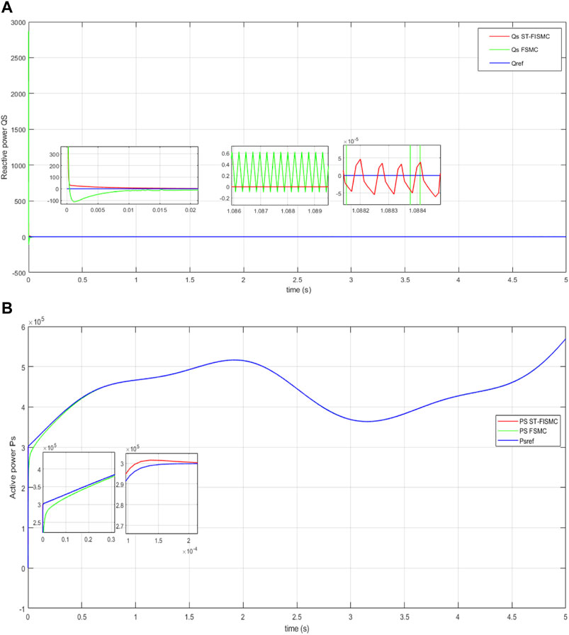
Figure 4. (A) Time response of reactive power without perturbation. (B) Time response of active power without perturbation.
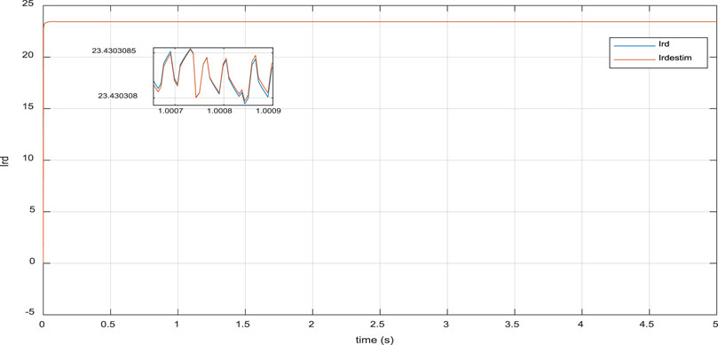
Figure 6. Time response of real rotor current
7.3.2 Case 2
In order to prove the robustness of the proposed control law and the adaptive observer, the studied system was subjected to randomly bounded parameter uncertainties in the Doubly Fed Induction Generator (DFIG) and unknown external disturbances affecting mechanical rotational speed sensor. Simulation was conducted in two scenarios as follows.
7.3.2.1 Scenario 1
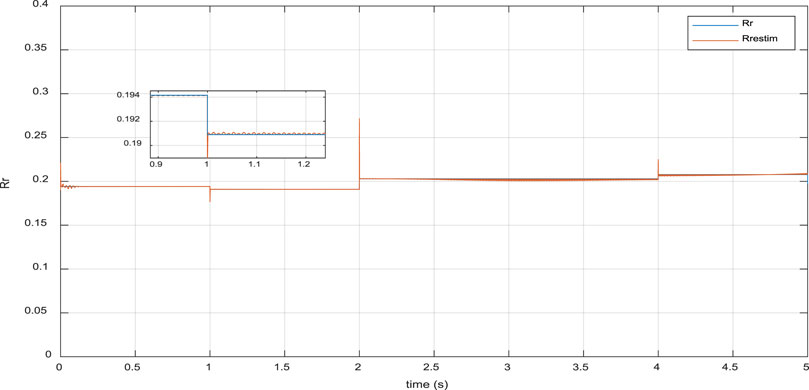
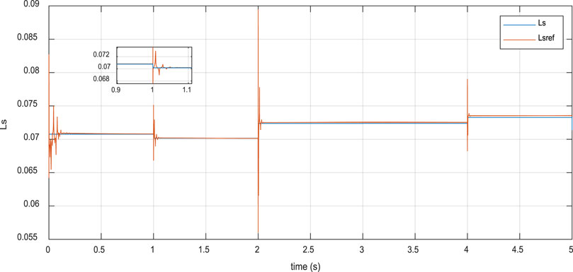
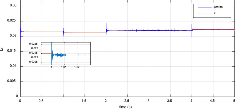
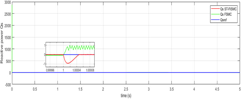
This section presents the simulation results of a faulty Doubly Fed Induction Generator (DFIG), where its parameters were assumed to be affected by nonlinearities in the wind. However, rotor resistance (Rr), stator inductance (Ls), and rotor inductance (Lr) deviated from their nominal values with small range bounded uncertainties. The maximum bounded uncertainty for Rr was about 10% of its nominal value, while Ls and Lr varied within a maximum range of 5% of their nominal values. Figures 8–10 demonstrate the effectiveness of the proposed adaptive observer in the online estimation of DFIG parameters. As illustrated in Figures 11, 12, the proposed Sliding-Mode Terminal Fuzzy Adaptive Sliding Mode Control (ST-FASMC) law has shown its efficiencies in terms of robustness against parameter uncertainties, where active and reactive power remained close to their nominal values in a finite and small response time of less than
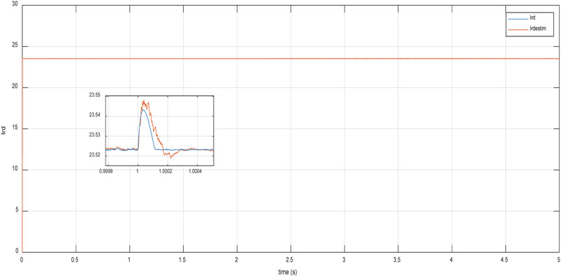
Figure 14. Time response of real rotor current
8 Conclusion
In this paper, we presented a new adaptive passive fault-tolerant control (AP-FTC) based on a fractional integral sliding-mode controller with auto-tuning (ST- FISMC) for a variable-speed wind turbine using a doubly-fed induction generator (DFIG). The objective is to improve energy efficiency while considering nonlinearities and a certain range of parametric uncertainties, whether at the electrical or mechanical level. The proposed approach stands out by using a nonlinear terminal hyperbolic cosine function to evaluate the tracking error in the sliding surface. This function allows for automatic adaptation of the equivalent control law by adjusting the power rate and the gain of the hyperbolic function, thus ensuring system stability in a finite time in case of failure. Additionally, fractional derivatives and integrals is used as a second measure to enhance stability and reduce undesired chattering. Furthermore, online estimation of electrical parameters is ensured using an adaptive sliding mode observer. Simulations are carried out in Matlab/Simulink considering two different operational conditions: first, the Doubly Fed Induction Generator (DFIG) based on the Variable Wind Turbine (VWT) operates under normal conditions, then the DFIG parameters undergo variations, and the mechanical rotation speed sensor is disturbed by unknown external factors. Simulation results show that the proposed approach offers better performance in capturing optimal wind energy, as well as the ability to regulate active/reactive power and high resilience to external disturbances.
Data availability statement
The original contributions presented in the study are included in the article/Supplementary Material, further inquiries can be directed to the corresponding authors.
Author contributions
IB: Conceptualization, Formal Analysis, Methodology, Resources, Software, Writing–original draft, Writing–review and editing. MM: Conceptualization, Formal Analysis, Methodology, Resources, Software, Writing–original draft, Writing–review and editing. KK: Conceptualization, Formal Analysis, Methodology, Resources, Software, Supervision, Writing–original draft, Writing–review and editing. AA: Formal Analysis, Investigation, Methodology, Supervision, Validation, Visualization, Writing–original draft, Writing–review and editing. AM: Formal Analysis, Funding acquisition, Investigation, Methodology, Resources, Validation, Visualization, Writing–review and editing.
Funding
The author(s) declare that financial support was received for the research, authorship, and/or publication of this article. This research was funded by Prince Sultan University, Riyadh, Saudi Arabia. This research was also supported by the Automated Systems and Soft Computing Lab (ASSCL), Prince Sultan University, Riyadh, Saudi Arabia.
Acknowledgments
The authors would like to thank Prince Sultan University, Riyadh, Saudi Arabia, for support with the article processing charges (APC) of this publication. The authors specially acknowledge the Automated Systems and Soft Computing Lab (ASSCL) at Prince Sultan University, Riyadh, Saudi Arabia. The authors wish to acknowledge the editor and reviewers for their insightful comments, which have improved the quality of this publication.
Conflict of interest
The authors declare that the research was conducted in the absence of any commercial or financial relationships that could be construed as a potential conflict of interest.
Publisher’s note
All claims expressed in this article are solely those of the authors and do not necessarily represent those of their affiliated organizations, or those of the publisher, the editors and the reviewers. Any product that may be evaluated in this article, or claim that may be made by its manufacturer, is not guaranteed or endorsed by the publisher.
References
Abdelmalek, S., Azar, A. T., and Dib, D. (2018). A novel actuator fault-tolerant control strategy of DFIG-based wind turbines using Takagi-Sugeno multiple models. Int. J. Control, Automation Syst. 16, 1415–1424. doi:10.1007/s12555-017-0320-y
Abdelrahim, M., and Almakhles, D. (2023). Output feedback stabilization of doubly fed induction generator wind turbines under event-triggered implementations. J. Sens. Actuator Netw. 12 (5), 64. doi:10.3390/jsan12050064
Ahmad, S., Ullah, N., Ahmed, N., Ilyas, M., and Khan, W. (2017). Super twisting sliding mode control algorithm for developing artificial pancreas in type 1 diabetes patients. Biomed. Signal Process. Control 38, 200–211. doi:10.1016/j.bspc.2017.06.009
AL-Wesabi, I., Zhijian, F., Jiuqing, C., Farh, H. M. H., Aboudrar, I., Dagal, I., et al. (2024). Fast DC-link voltage control based on power flow management using linear ADRC combined with hybrid salp particle swarm algorithm for PV/wind energy conversion system. Int. J. Hydrogen Energy 61 688–709. doi:10.1016/j.ijhydene.2024.02.325
Ammar, H. H., Azar, A. T., Shalaby, R., and Mahmoud, M. I. (2019). Metaheuristic optimization of fractional order incremental conductance (FO-INC) maximum power point tracking (MPPT). Complexity 2019, 1–13. Article ID 7687891. doi:10.1155/2019/7687891
Azar, A. T., and Serrano, F. E. (2015). “Stabilization and control of mechanical systems with backlash,” in Advanced intelligent control engineering and automation, advances in computational intelligence and robotics (ACIR) book series (United States: IGI-global).
Bakou, Y., Saihi, L., Koussa, K., Ferroudji, F., Roumani, K., Meguellati, K., et al. (2019) “Design of robust control based on H∞ approach of DFIG for wind energy system,” in First global power, energy and communication conference (GPECOM), Cappadocia, Turkey, June 12–15, 2019.
Benbouhenni, H., Yessef, M., Bizon, N., Kadi, S., Bossoufi, B., and Alhejji, A. (2024). Hardware-in-the-loop simulation to validate the fractional-order neuro-fuzzy power control of variable-speed dual-rotor wind turbine systems. Energy Rep. 11 (2024), 4904–4923. doi:10.1016/j.egyr.2024.04.049
Bhattarai, R., Gurung, N., and Kamalasadan, S. (2016). “Minimum variance controller based adaptive control for doubly fed induction generator,” in 2016 North American power symposium (NAPS), Denver, CO, September 18–20, 2016 (IEEE), 1–6.
Bossoufi, B., Aroussi, H. A., Ziani, E. M., Karim, M., Lagrioui, A., Derouich, A., et al. (2014). “Robust adaptive backstepping control approach of DFIG generators for wind turbines variable-speed,” in International renewable and sustainable energy conference (IRSEC), Ouarzazate, Morocco, October 17–19, 2014 (IEEE), 791–797.
Chakraborty, A., and Maity, T. (2023). An adaptive fuzzy logic control technique for LVRT enhancement of a grid-integrated DFIG-based wind energy conversion system. ISA Trans. 138, 720–734. doi:10.1016/j.isatra.2023.02.013
Dhanraj, J. A., Alkhawaldeh, R. S., Van De, P., Sugumaran, V., Ali, N., Lakshmaiya, N., et al. (2022b) Appraising machine learning classifiers for discriminating rotor condition in 50 W-12V operational wind turbine for maximizing wind energy production through feature extraction and selection process. Front. Energy Res. 10, 925980. doi:10.3389/fenrg.2022.925980
Dhanraj, J. A., Prabhakar, M., Ramaian, C. P., Subramaniam, M., Solomon, J. M., and Vinayagam, N. (2022a). “Increasing the wind energy production by identifying the state of wind turbine blade,” in Technology innovation in mechanical engineering. Lecture notes in mechanical engineering. Editors P. K. Chaurasiya, A. Singh, T. N. Verma, and U. Rajak (Singapore: Springer). doi:10.1007/978-981-16-7909-4_13
Dida, A., Merahi, F., and Mekhilef, S. (2020). New grid synchronization and power control scheme of doubly-fed induction generator based wind turbine system using fuzzy logic control. Comput. Electr. Eng. 84, 106647. doi:10.1016/j.compeleceng.2020.106647
Djeghali, N., Ghanes, M., Djennoune, S., and Barbot, J. P. (2013). Sensorless fault tolerant control for induction motors. Int. J. Control Automation Syst. 11, 563–576. doi:10.1007/s12555-012-9224-z
Durgam, R., Karampuri, R., Rangarajan, S. S., Subramaniam, U., Collins, E. R., and Senjyu, T. (2022). Investigations on the modulation strategies for performance improvement of a controlled wind energy system. Electronics 11 (23), 3931. doi:10.3390/electronics11233931
Eskandari, A., Vatankhah, R., and Azadi, E. (2023). Optimization of wind energy extraction for variable speed wind turbines using fuzzy backstepping sliding mode control based on multi objective PSO. Ocean. Eng. 285 (Part 2), 115378. doi:10.1016/j.oceaneng.2023.115378
Gao, X., Wang, Z., Ding, L., Bao, W., Wang, Z., and Hao, Q. (2024). A novel virtual synchronous generator control scheme of DFIG-based wind turbine generators based on the rotor current-induced electromotive force. Int. J. Electr. Power & Energy Syst. 156, 109688. doi:10.1016/j.ijepes.2023.109688
Global Electricity Consumption (2022). Available at: https://www.statista.com/statistics/280704/world-power-consumption/ (Accessed on May 5, 2024).
Global Wind Energy Council (2022). Global wind statistics. Available at: https://gwec.net/global-wind-report-2022/ (Accessed on May 5, 2024).
Hace, A. (2019). The advanced control approach based on SMC design for the high-fidelity haptic power lever of a small hybrid electric aircraft. Energies 12 (15), 2974.
Hu, J., He, Y., Xu, L., and Williams, B. W. (2008). Improved control of DFIG systems during network unbalance using PI–R current regulators. IEEE Trans. industrial Electron. 56 (2), 439–451. doi:10.1109/tie.2008.2006952
Jaikrishna, M. A., Venkatesh, S. N., Sugumaran, V., Dhanraj, J. A., Velmurugan, K., Sirisamphanwong, C., et al. (2023). Transfer learning-based fault detection in wind turbine blades using radar plots and deep learning models. Energy Sources A Recovery Util. Environ. Eff. 45 (4), 10789–10801. doi:10.1080/15567036.2023.2246400
Jiang, C., Cai, G., Yang, D., Liu, X., Hao, S., and Li, B. (2024). Multi-objective configuration and evaluation of dynamic virtual inertia from DFIG based wind farm for frequency regulation. Int. J. Electr. Power & Energy Syst. 158, 109956. doi:10.1016/j.ijepes.2024.109956
Kalel, D., and Raja Singh, R. (2024). IoT integrated adaptive fault tolerant control for induction motor based critical load applications. Eng. Sci. Technol. Int. J. 51, 101585. doi:10.1016/j.jestch.2023.101585
Kamal, N. A., and Ibrahim, A. M. (2018). “Conventional, intelligent, and fractional-order control method for maximum power point tracking of a photovoltaic system: a review,” in Fractional order systems optimization, control, circuit realizations and applications, advances in nonlinear dynamics and chaos (ANDC) (Elsevier), 603–671.
Kamarzarrin, M., Refan, M. H., and Amiri, P. (2022). Open-circuit faults diagnosis and fault-tolerant control scheme based on sliding-mode observer for DFIG back-to-back converters: wind turbine applications. Control Eng. Pract. 126, 105235. doi:10.1016/j.conengprac.2022.105235
Kesavan, P. K., Subramaniam, U., Almakhles, D. J., and Selvam, S. (2024). Modelling and coordinated control of grid connected photovoltaic, wind turbine driven PMSG, and energy storage device for a hybrid DC/AC microgrid. Prot. Control Mod. Power Syst. 9 (1), 154–167. doi:10.23919/PCMP.2023.000272
Ko, H., Yoon, G., Kyung, N., and Hong, W. P. (2008). Modeling and control of DFIG-based variable-speed wind-turbine. Electr. Power Syst. Res. 78, 1841–1849. doi:10.1016/j.epsr.2008.02.018
Li, D., Lin, X., Hu, S., and Kang, Y. (2010). “An adaptive estimation method for parameters of doubly-fed induction generators (DFIG) in wind power controller,” in 2010 Asia-Pacific power and energy engineering conference, Chengdu, China, March 28–31, 2010 (IEEE), 1–4. doi:10.1109/APPEEC.2010.5448313
Lin, X., Xiahou, K., Liu, Y., and Wu, Q. H. (2018). Design and hardware-in-the-loop experiment of multiloop adaptive control for DFIG-WT. IEEE Trans. Industrial Electron. 65 (9), 7049–7059. doi:10.1109/tie.2018.2798566
Mahmoud, T. K., Dong, Z. Y., and Ma, J. (2016). A developed integrated scheme based approach for wind turbine intelligent control. IEEE Trans. Sustain. energy 8 (3), 927–937. doi:10.1109/tste.2016.2632104
Majout, B., Bossoufi, B., Karim, M., Skruch, P., Mobayen, S., El Mourabit, Y., et al. (2024). Artificial neural network-based direct power control to enhance the performance of a PMSG-wind energy conversion system under real wind speed and parameter uncertainties: an experimental validation. Energy Rep. 11, 4356–4378. ISSN 2352-4847. doi:10.1016/j.egyr.2024.03.039
Mazare, M. (2024) Adaptive optimal secure wind power generation control for variable speed wind turbine systems via reinforcement learning, Appl. Energy, 353, Part A, 122034. doi:10.1016/j.apenergy.2023.122034
Mechter, A., Kemih, K., and Ghanes, M. (2015). Sliding mode control of a wind turbine with exponential reaching law. Acta Polytech. Hung. 12 (3), 167–183. doi:10.12700/APH.12.3.2015.3.10
Mechter, A., Kemih, K., and Ghanes, M. (2016). Backstepping control of a wind turbine for low wind speeds. Nonlinear Dyn. 84, 2435–2445. doi:10.1007/s11071-016-2655-y
Meghni, B., Dib, D., Azar, A. T., Ghoudelbourk, S., and Saadoun, A. (2017). “Robust adaptive supervisory fractional order controller for optimal energy management in wind turbine with battery storage,” in Studies in computational intelligence (Germany: Springer-Verlag), 688, 165–202. doi:10.1007/978-3-319-50249-6_6
Messadi, M., and Mellit, A. (2017). Control of chaos in an induction motor system with LMI predictive control and experimental circuit validation. Chaos, Solit. Fractals 97, 51–58. doi:10.1016/j.chaos.2017.02.005
Messadi, M., Mellit, A., Kemih, K., and Ghanes, M. (2015). Predictive control of a chaotic permanent magnet synchronous generator in a wind turbine system. Chin. Phys. B 24 (1), 010502. doi:10.1088/1674-1056/24/1/010502
Mohan, V., Chhabra, H., Rani, A., and Singh, V. (2018). Robust self-tuning fractional order PID controller dedicated to non-linear dynamic system. J. Intelligent Fuzzy Syst. 34, 1467–1478. doi:10.3233/jifs-169442
Monje, C. A., Chen, Y., Vinagre, B. M., Xue, D., and Feliu-Batlle, V. (2010). Fractional-order systems and controls fundamentals and applications. Springer Science & Business Media.
Naresh, K., Reddy, P. U., Sujatha, P., and Reddy, C. R. (2020). Control of DFIG based wind turbine with hybrid controllers. Int. J. Renew. Energy Res. 10 (3), 1488–1500.
Penghan, L., Jie, W., Linyun, X., Sunhua, H., Ziqiang, W., and Meiling, M. (2020). SSCI mitigation of grid-connected DFIG wind turbines with fractional-order sliding mode controller. 2020, 1–14. John Wiley & Sons, Ltd. doi:10.1002/we.2500
Ponce, P., Ponce, H., and Molina, A. (2018). Doubly fed induction generator (DFIG) wind turbine controlled by artificial organic networks. Soft Comput. 22, 2867–2879. doi:10.1007/s00500-017-2537-3
Poznyak, A. S., and Orlov, Y. V. (2023). Vadim I. Utkin and sliding mode control. J. Frankl. Inst. 360 (17), 12892–12921. doi:10.1016/j.jfranklin.2023.09.028
Rabah, K., and Ladaci, S. (2017) “A novel fractional order adaptive Sliding Mode Controller design for chaotic Arneodo systems synchronization,” in 6th international conference on systems and control (ICSC), Batna, Algeria, May 07–09, 2017 (IEEE), 465–469.
Reddak, M., Berdai, A., Gourma, A., and Belfqih, A. (2016). “Integral backstepping control based maximum power point tracking strategy for wind turbine systems driven DFIG,” in International conference on electrical and information technologies (ICEIT), Tangiers, Morocco, 04-07 May 2016, 84–88. doi:10.1109/EITech.2016.7519567
Saadaoui, A., and Ouassaid, M. (2024). Super-twisting sliding mode control approach for battery electric vehicles ultra-fast charger based on Vienna rectifier and three-phase interleaved DC/DC buck converter. J. Energy Storage 84 (Part B), 110854. doi:10.1016/j.est.2024.110854
Saha, B. C., Dhanraj, J. A., Sujatha, M., Vallikannu, R., Alanazi, M., Almadhor, A., et al. (2022). Investigating rotor conditions on wind turbines using integrating tree classifiers. Int. J. Photoenergy 1, 1. 14. doi:10.1155/2022/5389574
Saha, C., and Singh, A. K. (2019). “A review article on fault-tolerant control (FTC) and fault detection isolation (FDI) schemes of wind turbine,” in Proceeding of the second international conference on microelectronics, computing & communication systems (Singapore: Springer), 87–95.
Sepestanaki, M. A., Rezaee, H., Soofi, M., Fayazi, H., Rouhani, S. H., and Mobayen, S. (2024). Adaptive continuous barrier function-based super-twisting global sliding mode stabilizer for chaotic supply chain systems. Chaos, Solit. Fractals 182, 114828. doi:10.1016/j.chaos.2024.114828
Sethi, M. R., Sahoo, S., Dhanraj, J. A., and Sugumaran, V. (2023). Vibration signal-based diagnosis of wind turbine blade conditions for improving energy extraction using machine learning approach. ASTM Int. Smart Sustain. Manuf. Syst. 7 (1), 14–40. doi:10.1520/SSMS20220023
Shi, F., and Patton, R. (2015). An active fault tolerant control approach to an offshore wind turbine model. Renew. Energy 75, 788–798. doi:10.1016/j.renene.2014.10.061
Singh, S., Azar, A. T., Ouannas, A., Zhu, Q., Zhang, W., and Na, J. (2017) “Sliding mode control technique for multi-switching synchronization of chaotic systems,” in Proceedings of 9th international conference on modelling, identification and control (ICMIC 2017), Kunming, China, July 10–12, 2017. (IEEE), 880–885.
Slotine, J. J. E., and Li, W. (1991). Applied nonlinear control. Englewood Cliffs, NJ: Prentice-Hall, Inc.
Takhi, H., Moysis, L., Machkour, N., Volos, C., Kemih, K., and Ghanes, M. (2022). Predictive control and synchronization of uncertain perturbed chaotic permanent-magnet synchronous generator and its microcontroller implementation. Eur. Phys. J. Special Top. 231 (3), 443–451. doi:10.1140/epjs/s11734-021-00422-4
Valerio, D. (2005). Toolbox ninteger for MATLAB, version 2.3, sept. 2009. Available at: http://web.ist.utl.pt/duarte.valerio/ninteger/ninteger.htm.
Vásquez, M., Yanascual, J., Herrera, M., Prado, A., and Camacho, O. (2023). A hybrid sliding mode control based on a nonlinear PID surface for nonlinear chemical processes. Eng. Sci. Technol. Int. J. 40, 101361. doi:10.1016/j.jestch.2023.101361
Wang, X., and Shen, Y. (2019). Fault tolerant control of DFIG-based wind energy conversion system using augmented observer. Energies 12 (4), 580. doi:10.3390/en12040580
Xiahou, K., Liu, Y., Wang, L., Li, M. S., and Wu, Q. H. (2019). Switching fault-tolerant control for DFIG-based wind turbines with rotor and stator current sensor faults. IEEE Access 7, 103390–103403. doi:10.1109/access.2019.2931927
Yuan, T., Wang, J., Guan, Y., Liu, Z., Song, X., Che, Y., et al. (2018). Virtual inertia adaptive control of a doubly fed induction generator (DFIG) wind power system with hydrogen energy storage. Energies 11 (4), 904. doi:10.3390/en11040904
Zhang, M., Zang, H., and Bai, L. (2022). A new predefined-time sliding mode control scheme for synchronizing chaotic systems. Chaos, Solit. Fractals 164 (2022), 112745. doi:10.1016/j.chaos.2022.112745
Keywords: variable wind turbine, self-tuning fractional integral sliding mode control, hyperbolic fractional surface, chattering reduction, adaptive observer, flux estimation, parameter variation estimation
Citation: Bouguettah I, Messadi M, Kemih K, Azar AT and Mahlous AR (2024) Adaptive passive fault tolerant control of DFIG-based wind turbine using a self-tuning fractional integral sliding mode control. Front. Energy Res. 12:1429877. doi: 10.3389/fenrg.2024.1429877
Received: 08 May 2024; Accepted: 18 July 2024;
Published: 20 August 2024.
Edited by:
Joshuva Arockia Dhanraj, Dayananda Sagar University, IndiaReviewed by:
Sahaj Saxena, Thapar Institute of Engineering & Technology, IndiaDeepak Gupta, Maharaja Agrasen Institute of Technology, India
Copyright © 2024 Bouguettah, Messadi, Kemih, Azar and Mahlous. This is an open-access article distributed under the terms of the Creative Commons Attribution License (CC BY). The use, distribution or reproduction in other forums is permitted, provided the original author(s) and the copyright owner(s) are credited and that the original publication in this journal is cited, in accordance with accepted academic practice. No use, distribution or reproduction is permitted which does not comply with these terms.
*Correspondence: Karim Kemih, ay5rZW1paEBnbWFpbC5jb20=; Ahmad Taher Azar, YWF6YXJAcHN1LmVkdS5zYQ==
 Imene Bouguettah1
 Karim Kemih
 Ahmad Taher Azar
 Ahmed Redha Mahlous