- 1Foshan Power Supply Bureau of Guangdong Power Grid Co., Ltd. Guangdong Province, Foshan, China
- 2Electric Power Research Institute of Guangdong Power Grid Co., Ltd. Guangdong Province, Guangzhou, China
- 3Guangdong Power Grid Co., Ltd. Guangdong Province, Guangzhou, China
- 4Qingyuan Power Supply Bureau of Guangdong Power Grid Co., Ltd. Guangdong Province, Qingyuan, China
- 5Automation School, Wuhan University of Technology, Wuhan, China
In the background of the global commitment to low-carbon renewable energy transformation, new energy sources such as distributed wind–solar storage and charging and single-phase loads, such as electric vehicles, are connected to the distribution network. Due to the asymmetric access of load and the randomness of load power consumption, the problem of three-phase imbalance is becoming more and more prominent, and the uncertainty is increasing. In this paper, by analyzing the three-phase load imbalance problem of the distribution network, starting from the cause of three-phase load imbalance, the three-phase imbalance calculation method of the distribution network is deduced. The access mode of a distributed power flow controller in the distribution network and the three-phase imbalance compensation method are studied. The control strategy of the distributed power flow controller for the three-phase imbalance control of the distribution network is proposed. The simulation results show that the proposed method can effectively control the three-phase asymmetry problem of the distribution network, the configuration is more flexible, and the capacity utilization rate is higher.
1 Introduction
With the rapid development of smart grids, a large number of electric vehicle loads and new energy will be connected to the distribution network side. At the same time, due to the influence of season and electricity consumption habits, the single-phase load power consumption of the distribution network is random and asynchronous. If certain control measures are not taken, the medium- and low-voltage distribution network will be prone to three-phase imbalance. Uncertain single-phase new energy output increases load fluctuations and is difficult to accurately predict, which will lead to three-phase imbalance. The problem is more complex and serious (Song et al., 2022; Jiaqiao et al., 2022; Ji et al., 2020; Li et al., 2018; Shaaban et al., 2015; Keane et al., 2013; Leou et al., 2014; Borges, 2012; Singh et al., 2010). Ensuring three-phase balance is very important for the safe and economic operation of the distribution network. Severe three-phase imbalance will increase the energy loss of the system, reduce the available capacity of feeders and transformers, cause overheating and damage of three-phase equipment, lead to feeder tripping, and even cause power grid safety accidents (Dong et al., 2021; Wang et al., 2021; Ma et al., 2016; Mostafa et al., 2013; Ghatak et al., 2020).
In order to effectively control the three-phase imbalance problem of the distribution network, the governance goal can be achieved by equipping with passive or active compensation equipment. Araujolr et al. (2018) proposed an optimal configuration method of capacitor banks to reduce the imbalance and minimize the network loss. However, the adjustment rate of this method is limited, and it cannot cope with the rapid change in the load and the intermittent and random output fluctuation in photovoltaic power. Abas et al. (2020) proposed a dynamic voltage regulator, which injects voltage phasors with a specified amplitude and frequency into the transmission line to compensate the three-phase imbalanced voltage, so as to alleviate the voltage imbalance of the three-phase four-wire distribution network. Shahnia et al. (2014) proposed a distributed static synchronous compensator for the power quality control of the distribution network. By controlling the switch tube to adjust the amplitude and phase of the output voltage of the inverter AC side, the four-quadrant operation is realized, and the reactive power is quickly absorbed or emitted so as to have more flexibly control over the power quality problem of the distribution network. However, the D-STATCOM device is expensive, and the cost of installation and operation and maintenance is high. It is widely used in low-voltage distribution networks to control three-phase imbalances, but the economic cost is very high (Yao et al., 2019).
As flexible AC transmission equipment with a distributed split-phase arrangement on the line, the distributed power-flow controller (DPFC) can effectively suppress the asymmetry caused by the structural parameters of the line. Owing to the distributed structure of the DPFC, each series unit distributed on the line can automatically adjust the capacity on demand and can compensate for the asymmetry of the line structure without putting in all series units so as to ensure that the series units in each work have a higher operating efficiency, better flexibility, and stronger economy (Tang et al., 2023). Compared with D-STATCOM, the DPFC is composed of several sub-modules based on a single-phase voltage source converter. Each sub-module can complete tasks such as power flow control, three-phase imbalance compensation, and harmonic suppression independently or cooperatively. It has high reliability, is highly economical, and has strong flexibility and is very suitable for multi-branch and multi-section characteristics of the active distribution network. Tang et al. (2021) proposed a new distributed power-flow controller topology suitable for the distribution network, and the three-loop control series side is used to realize the power flow control of the distribution network feeder. Krishna et al. (2016) optimized the controller parameters of the DPFC by the fuzzy logic method, and the harmonic distortion problem of the distribution network is solved. Rajasekhar and Babu (2016) studied the ability of the DPFC to compensate for voltage sag in the case of a three-phase fault through example simulation. Lakshmi and Jyothsna (2016) verified the ability of the DPFC to improve the fault current and voltage in the case of a three-phase fault. Tang et al. (2019) proposed a DPFC multi-objective coordinated control strategy considering various constraints based on the constraints of DC capacitor voltage, injection voltage, and line power flow limit of the DPFC unit. Although some studies have studied the control strategies of the DPFC system level and device level, they mainly focus on the realization of the DPFC power flow control function, and there is no relevant research on the three-phase imbalance control problem in the active distribution network scenario.
Taking the medium- and low-voltage distribution network as an example, this paper analyzes the three-phase load balance problem of an active distribution network. Starting with the cause of three-phase load imbalance, the calculation method of three-phase imbalance in the distribution network is deduced. The access mode of the distributed power-flow controller in the distribution network and the compensation method of three-phase imbalance are studied. The control strategy of the distributed power flow controller for the three-phase imbalance control of the distribution network is proposed, and its effectiveness is verified by simulation.
2 Analysis of the three-phase load balance problem of the active distribution network
The structure of the distribution network is shown in Figure 1. Due to the randomness and asymmetric access of the user electricity, the three-phase load of the distribution network is imbalanced, resulting in an imbalanced voltage or imbalanced current of the system. With the improvement in people’s living standards, a large number of high-power single-phase home appliances are used, which aggravates the three-phase load imbalance problem of the low-voltage distribution network and affects the economic operation of the distribution network.
According to national standards, for low-voltage distribution networks, the current imbalance at the load common connection point is not more than 10% and the voltage is not more than 2%. The national standard for the precise definition of the three-phase imbalance degree is as follows (Qian et al., 2019):
In the formula,
In the formula,
In practical applications, the current imbalance caused by load is the most common. When the three-phase current imbalance is serious, it will cause a series of hazards such as increased line loss, reduced distribution transformer output, and increased motor loss.
In order to compare the difference of the same power line loss transmitted between the balanced system and the imbalanced system. The line impedance is
The three-phase total complex power of the balance system is
In the formula,
The line loss of the balance system is
When the system load current is asymmetric, the relationship between the phase current and the sequence component is
In the formula,
Then according to Equations 1–6, the three-phase total complex power of the imbalanced system is
Although the single-phase power of A, B, and C is different, the average power of the three-phase positive sequence voltage and negative sequence current is 0, that is, in the total output power, only the active and reactive power generated by the positive sequence voltage and positive sequence current. For a voltage symmetric system, if the output power of the balanced system is equal to that of the unbalanced system,
Formula 7 is squared on both sides and can be obtained by accumulation
In other words, for the power supply voltage symmetrical system, the transmission power is the same, and the positive sequence component of the unbalanced system current is equal to the balanced system current. Then according to Equation 8, the line loss of the unbalanced system is
It can be seen that the three-phase unbalanced system will increase the line loss. In addition, the operation of the distribution transformer in the three-phase imbalanced condition will lead to a large increase in its copper consumption and an increase in the heat of the overload phase. Due to the asymmetry of the three-phase magnetic circuit, a large amount of magnetic flux leakage passes through the clamp and the oil tank, causing additional losses, resulting in very high temperature of the transformer and shortened insulation life.
The three-phase imbalance will also cause the neutral point potential of the system to shift, resulting in a low- or high-phase voltage, which will damage the lighting equipment and user lighting experience in the low-voltage distribution network, and reduce the life of household appliances. In addition, three-phase unbalance will lead to non-characteristic harmonics in AC equipment with semiconductor devices, and the voltage unbalance exceeds the design threshold.
3 Three-phase imbalance control strategy of the distributed power flow controller
3.1 Analysis of the three-phase load imbalance control principle based on the distributed power flow controller
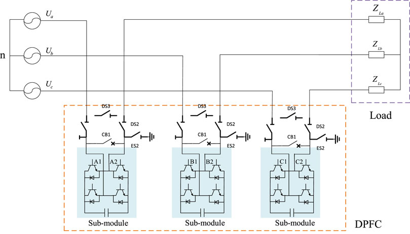
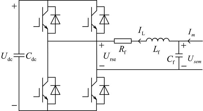
The distributed power flow controller is composed of three single-phase sub-modules. Each sub-module can be operated and controlled independently. It has strong redundancy, can be dispersed on the line, and has strong flexibility. It is very suitable for the distribution network with a complex network structure and dense load. The topology and installation method of the sub-module of the distributed power flow controller are shown in Figure 3 and Figure 4. The thyristor bypass switch (TBS) and the fast mechanical bypass switch are configured in the DPFC sub-module, and the action time of the bypass switch is hundreds of microseconds. When an extreme condition occurs in a phase of the distribution network, the sub-module quickly and automatically exits and no longer outputs the equivalent impedance, and the remaining sub-modules of the unfaulted phase can continue to operate.
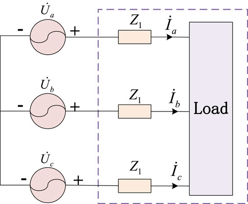
The distributed power flow controller can be equivalent to the impedance mode, power mode, and voltage source mode. In this paper, the DPFC is used to compensate for the asymmetry of the three-phase load in the distribution network. By controlling the output voltage of each sub-module of the DPFC, the actual working voltage of the load is changed so that the three-phase line current is balanced. The equivalent circuit diagram of the distribution network after the installation of the distributed power flow controller is shown in Figure 5, where
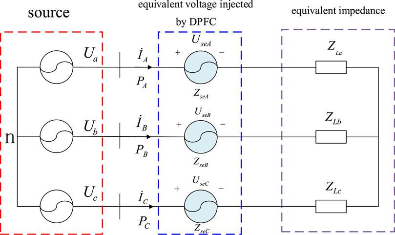
Figure 5. Equivalent circuit diagram of the distribution network after the installation of the DPFC.
Figure 5 shows that after the DPFC is installed, the three-phase line impedance is
Assuming that the three-phase supply voltage is balanced, by controlling the output voltage of each sub-module of the distributed power flow controller,
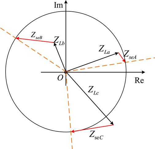
Figure 6. Phasor diagram based on the three-phase load imbalance compensation principle of the distributed power flow controller.
3.2 Three-phase load balance control strategy based on the distributed power flow controller
From the analysis of Section 3.1, it can be seen that the DPFC can change the equivalent impedance of the three-phase line by controlling the output voltage of the distributed power flow device to make it equal and achieve three-phase current balance when dealing with three-phase load imbalance. Figure 5 is equivalent to Figure 7; in the figure,
Figure 7 shows that the active power of the three-phase line is
In the formula,
Equation 12 shows that when the three-phase load current reaches equilibrium, that is, the three-phase impedance amplitude is equal, the active power of the A, B, and C three-phase lines is equal. Therefore, when the distributed power flow controller is used for load current compensation, the three-phase circuit power balance can be controlled to achieve equal three-phase load impedance, thereby achieving the line three-phase load current balance.
In order not to affect the load of each phase of the branch line, the active power command of each phase line should be
Substituting Equation 13 into Equation 12, it can be seen that the impedance value that the DPFC needs to compensate is
In the equation,
At this time, the effective value of each phase line current
Thus, the injection voltage A of the DPFC sub-module in each phase can be calculated as
The accuracy of the DPFC total injection voltage instruction
In order to solve this problem, this paper proposes a power flow control strategy based on the PI controller: taking the deviation signal
Through the feedback control mechanism, the DPFC can continuously change the output state and finally reach the stable state of zero static error.
When regulating the line power flow, the DPFC needs to exchange the active power in the power grid to maintain the stability of the DC capacitor voltage. At the same time, it needs to invert the corresponding compensation voltage to regulate the line power flow to reach the command value. According to Equation 11, the output voltage command of the DPFC is calculated, and the SPWM voltage of the single-phase inverter is changed so that the voltage transmitted by each sub-module of the DPFC follows the voltage command to realize the power flow control function. From Figure 5, the mathematical model of the DPFC sub-module in the dq rotating coordinate system is
The line power flow control is essential to control the output voltage of the DPFC. Equation 17 shows that the adjustment of the line power flow can be transformed into the control of the d-axis component and the q-axis component of the DPFC output voltage. In order to achieve the DPFC output voltage to the d-axis component and the q-axis component command error-free tracking, the inner loop control proposed in this paper is as follows:
In the formula,
Since the DPFC needs to absorb active power from the grid to maintain DC capacitor voltage stability, the outer loop control of the DPFC sub-module is expressed as
According to Formula 18–Formula 19, the control block diagram of DPFC three-phase unbalance control can be obtained, as shown in Figure 9.
Formula 9 shows that when the output power of the balanced system is the same as that of the unbalanced system, after the unbalanced system is adjusted to the balanced system, the loss reduction of the balanced system compared with the original unbalanced system is
When the three-phase unbalanced system is connected to the DPFC and the above control strategy is adopted, the DPFC further realizes the three-phase balance by changing the impedance Z1 of the line. When the DPFC is connected to the system, the output power of the balanced system and the unbalanced system is no longer the same. Compared with the original unbalanced system, the loss reduction of the balanced system is
In the formula,
4 Simulation analysis
In order to verify the effectiveness of the unbalanced control strategy based on the distributed power flow controller proposed in this paper, the distribution network system is constructed, as shown in Figure 10.
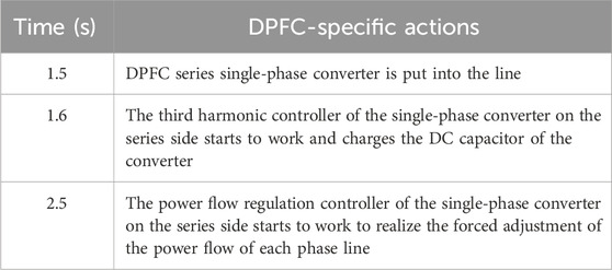
The corresponding PSCAD/EMTDC-based simulation model is shown in Figure 11. DPFC series-side units are installed on nodes 1–2, and multiple sets of single-phase converters distributed on the series side are evenly distributed on the line. The specific parameters are shown in Table 1, and the specific action steps of the DPFC are shown in Table 2.
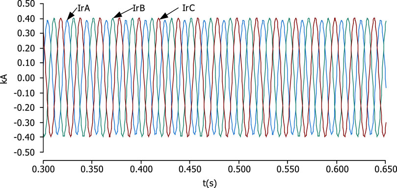
Before the DPFC was not put into operation, due to the asymmetry of the system structure, the line current also showed an asymmetric phenomenon, and the line current waveform is shown in Figure 12. The symmetrical component analysis shows that the positive sequence current is 0.2789 kA, the negative sequence current is 0.0068 kA, the zero sequence current is approximately 0 kA, and the asymmetry is 2.43%.
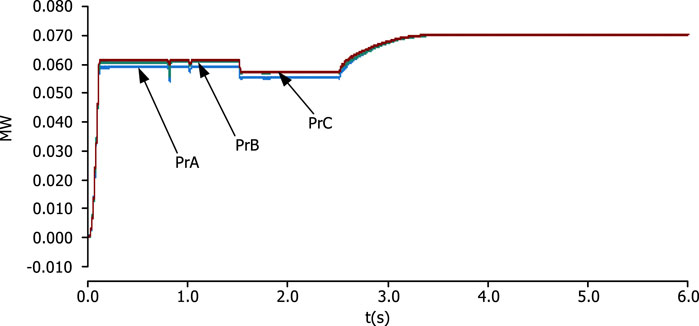
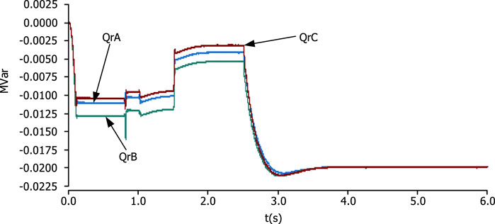
Due to the asymmetry of line current, the active power flow and reactive power flow of each phase line are not exactly the same. The DPFC has the effect of forced adjustment of the line. When the DPFC is put into operation, the changes in the active power flow and reactive power flow in each phase are shown in Figures 13, 14, respectively.
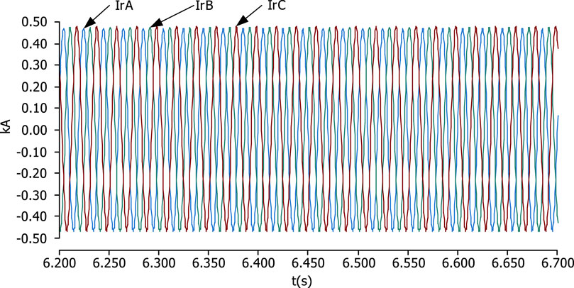
Figures 13, 14 show that before 2.5 s, the line power flow has been in a natural distribution state because the power flow regulation module of the series-side converter has not yet started to work. At 1.5 s, two sets of converters on the series side are put into the line. Between 1.6 s and 2.5 s, since only the third harmonic control module is put into the series side, the module only plays a role in maintaining the DC capacitor voltage of the converter, so the active power flow and reactive power flow of each phase line remain asymmetric. After the power flow adjustment module is put into operation in 2.5 s, the active power flow and reactive power flow of A, B, and C three-phase lines smoothly reach the given values of 0.07 MW and 0.02 MVar, respectively. The response time of active power flow is approximately 0.9 s, and the response time of reactive power flow is approximately 1 s. The stabilized line current is shown in Figure 15.
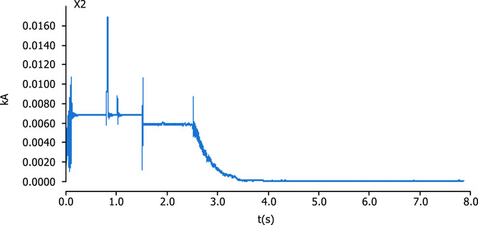
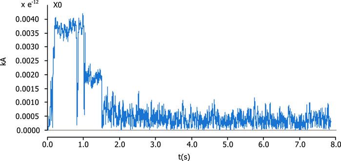
The figure shows that after the DPFC is put into operation, the three-phase currents of A, B, and C are completely symmetrical. In order to better analyze, this experiment also analyzes the symmetrical component method of the line current before and after the DPFC is put into operation. The results are shown in Figures 16–18.
The above three diagrams show the positive sequence, negative sequence, and zero-sequence components of the line current, respectively. In the analysis of Figure 12, the DPFC is not put into work, that is, before 0.8 s, the line asymmetry is 2.43%. In the analysis of Figures 13, 14, it is also mentioned that the line current will remain asymmetrical before the power flow regulation module on the DPFC series side is put into operation, that is, before 2.5 s. Figure 17 shows that the negative sequence current of the line was approximately 0.006 kA before 2.5 s. Only after the power flow regulation module is put into operation at 2.5 s, the negative sequence current of the line begins to decrease smoothly to 0, and the response time is close to the line power flow response time, which just shows that the power flow regulation module on the series side of the DPFC has the effect of forcing the line current to control. Figure 16 shows the curve variation in the positive sequence current of the line, and the trend is similar to the change in the active power flow of the line. This is because in the transmission line with a high power factor, the amplitude of the line current is proportional to the active power of the line. Figure 18 shows the zero-sequence component of the line current, but because the zero-sequence current component of the line is very small, it can be ignored.
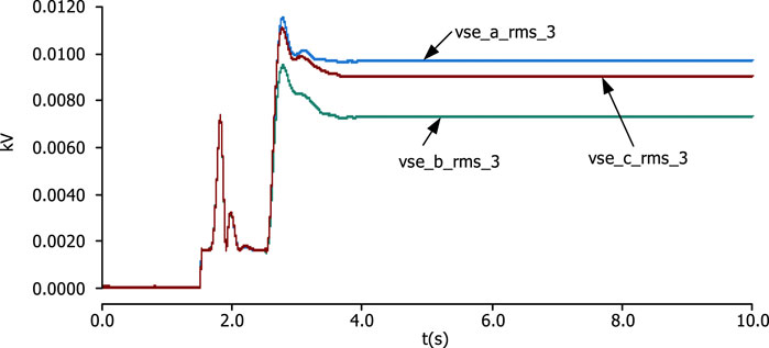
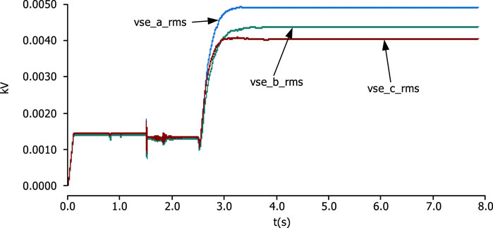
The above phenomena show that the DPFC can effectively improve the asymmetry of line current caused by the asymmetry of the system structure, which is all due to the arrangement strategy of single-phase distributed installation on the series side of the DPFC. Because the line structure parameters of each phase are different, the output power of each phase converter is also different. As shown in Figures 19, 20, in Figure 19, the effective value of the third harmonic voltage of the single-phase inverter of the series side A, B, and C three-phase single-phase converter is stabilized at 0.0096 kV, 0.0073 kV, and 0.0090 kV, respectively, after 2.5 s. In Figure 20, the effective values of the fundamental voltage of the single-phase converters of A, B, and C on the series side are stabilized at 0.0047 kV, 0.0044 kV, and 0.0041 kV after 2.5 s, respectively, which characterizes that the series-side A, B, and C three-phase lines are compensated to varying degrees, and finally, the current of the three-phase lines A, B, and C is symmetrical. At this time, according to Equations 20, 21, the loss reduction of the simulation system is 743.1 W, and the loss of the system is reduced, which further illustrates the effectiveness of using the DPFC for three-phase imbalance control.
5 Conclusion
In this paper, the problem of three-phase load imbalance in the distribution network is analyzed, and the calculation method of the three-phase imbalance in the distribution network is deduced. The access mode and compensation method of the distributed power flow controller for three-phase imbalance control of the distribution network are given. The control strategy of the distributed power flow controller for the three-phase load imbalance control of the distribution network is proposed, and the simulation verification is carried out. The following conclusions are obtained.
1) The suppression of line current asymmetry is mainly the series-side unit of the DPFC-distributed phase arrangement on the line. The function of the DPFC to control the power flow of each phase is used to make the circuit of A, B, and C three-phase lines symmetrical, which verifies the feasibility of the DPFC to control three-phase asymmetry.
2) The ability of the DPFC to suppress three-phase asymmetry is verified, which can effectively reduce the additional loss caused by asymmetry and improve the power supply economy of the distribution network.
3) It is verified that the series side of the DPFC can automatically adjust the capacity according to the different compensation degrees of each phase line, which reflects the superiority of DPFC distribution. In the medium- and low-voltage distribution network with serious asymmetry, this feature of the DPFC can make the configuration of each phase capacity more flexible and the capacity utilization rate higher.
Data availability statement
The original contributions presented in the study are included in the article/Supplementary Material; further inquiries can be directed to the corresponding author.
Author contributions
GG: conceptualization, methodology, writing–original draft, and writing–review and editing. XZ: formal analysis, writing–original draft, and writing–review and editing. JW: conceptualization, methodology, writing–original draft, and writing–review and editing. ZL: conceptualization, methodology, writing–original draft, and writing–review and editing. KF: data curation, writing–original draft, and writing–review and editing. FP: formal analysis, writing–original draft, and writing–review and editing. DG: formal analysis, writing–original draft, and writing–review and editing. AT: conceptualization, data curation, methodology, writing–original draft, and writing–review and editing. CX: conceptualization, writing–original draft, and writing–review and editing. ZW: data curation, writing–original draft, and writing–review and editing.
Funding
The author(s) declare that financial support was received for the research, authorship, and/or publication of this article. The first author is grateful to the China Southern Power Grid. The work received funding from the “China Southern Power Grid” through the project “Research on New Distributed Power Flow Control and New Flexible Distribution Transformer Technology” (project number GDKJXM20222475).
Acknowledgments
The authors acknowledge the China Southern Power Grid Power Grid Project for funding.
Conflict of interest
Authors GG and XZ were employed by Guangdong Power Grid Co.
Author JW was employed by Guangdong Power Grid Co.
Authors ZL, KF, and FP were employed by Guangdong Power Grid Co.
Author DG was employed by the Qingyuan Power Supply Bureau of Guangdong Power Grid Co.
Publisher’s note
All claims expressed in this article are solely those of the authors and do not necessarily represent those of their affiliated organizations, or those of the publisher, the editors, and the reviewers. Any product that may be evaluated in this article, or claim that may be made by its manufacturer, is not guaranteed or endorsed by the publisher.
References
Abas, N., Dilshad, S., Khalid, A., Saleem, M. S., and Khan, N. (2020). Power quality improvement using dynamic voltage restorer. IEEE Access 8, 164325–164339. doi:10.1109/access.2020.3022477
Araujolr, D. E., Penido, D. R. R., Carneiro, S., and Pereira, J. L. R. (2018). Optimal unbalanced capacitor placement in distribution systems for voltage control and energy losses minimization. Electr. Power Syst. Res. 154, 110–121. doi:10.1016/j.epsr.2017.08.012
Borges, C. L. T. (2012). An overview of reliability models and methods for distribution systems with renewable energy distributed generation. Renew. and Sustain. Energy Rev. 16 (6), 4008–4015. doi:10.1016/j.rser.2012.03.055
Dong, X., Hua, Z., Shang, L., Wang, B., Chen, L., and Zhang,, Q. (2021). Morphological characteristics and technology prospect of new distribution system[J]. High. Volt. Eng. 47(9):3021–3035.
Ghatak, S. R., Sannigrahi, S., and Acharjee, P. (2020). Multiobjective framework for optimal integration of solar energy source in three-phase unbalanced distributionnetwork. IEEE Trans. Industry Appl. 56 (3), 3068–3078. doi:10.1109/tia.2020.2968046
Zhenya, J., Xueliang, X., Ziqi, Z., Ming, J., and Qingqiang, X. (2020). Evaluating the vehicle-to-grid potentials by electric vehicles:a quantitative study in China by 2030[C]//2020. Montreal, Canada: IEEE Power and Energy Society General Meeting PESGM.
Jiaqiao, Li, Wang, G., and Zhang, M. (2022). Automatic commutation device location and capacity planning for three-phase unbalance control in the station area. Power Syst. autom. 46 (19). doi:10.7500/AEPS20211031002
Keane, A., Ochoa, L. F., Borges, C. L. T., Ault, G. W., Alarcon-Rodriguez, A. D., Currie, R. A. F., et al. (2013). State-of-the-art techniques and challenges ahead for distributed generation planning and optimization. IEEE Trans. Power Syst. 28 (2), 1493–1502. doi:10.1109/tpwrs.2012.2214406
Krishna, B. V., Prashanth, B. V., and Anjaneyulu, K. S. R. (2016). Designing of multilevel DPFC to improve power quality[C]. 2016 international conference on electrical, electronics, and optimization techniques. India: IEEE, 4129–4133.
Lakshmi, V. A., and Jyothsna, T. R. (2016) “Mitigation of voltage and current variations due to three phase fault in a single machine system using distributed power flow controller[C],” in 2016 international conference on electrical, electronics, and optimization techniques, India. IEEE, 267–277.
Leou, R., Su, C., and Lu, C. (2014). Stochastic analyses of electric vehicle charging impacts on distribution network. IEEE Trans. Power Syst. 29 (3), 1055–1063. doi:10.1109/tpwrs.2013.2291556
Li, Y., Xie, K., Wang, L., and Xiang, Y. (2018). The impact of PHEVs charging and network topology optimization on bulk power system reliability. Electr. Power Syst. Res. 163, 85–97. doi:10.1016/j.epsr.2018.06.002
Ma, K., Li, R., and Li, F. (2016). Quantification of additional asset reinforcement cost from 3-phase imbalance. IEEE Trans. Power Syst. 31 (4), 2885–2891. doi:10.1109/tpwrs.2015.2481078
Mostafa, H. A., El-Shatshat, R., and Salama, M. M. A. (2013). Multi-objective optimization for the operation of an electric distribution system with a large number of single phase solar generators. IEEE Trans. Smart grid 4 (2), 1038–1047. doi:10.1109/tsg.2013.2239669
Qian, H., Xufeng, Y., Zhihua, X., Yong, Y., Mingyang, C., and Teng, X. (2019). Review of Three-phase Load Unbalance in Distribution Network[J]. Energy Conserv. Technol. 37 (06), 549–556.
Rajasekhar, A. N. V. V., and Babu, M. N. (2016) “Harmonics reduction and power quality improvement by using DPFC,” in 2016 international conference on electrical, electronics, and optimization techniques, India. IEEE, 3790–3799.
Shaaban, M. F., Eajal, A. A., and EL-Saadany, E. F. (2015). Coordinated charging of plug-in hybrid electric vehicles in smart hybrid AC/DC distribution systems. Renew. Energy2015 82, 92–99. doi:10.1016/j.renene.2014.08.012
Shahnia, F., Ghosh, A., Ledwich, G., and Zare, F. (2014). Voltage unbalance improvement in low voltage residential feeders with rooftop PVs using custom power devices. Int. J. Electr. Power and Energy Syst. 55, 362–377. doi:10.1016/j.ijepes.2013.09.018
Singh, M., Khadkikar, V., Chandra, A., and Varma, R. K. (2010). Grid interconnection of renewable energy sources at the distribution level with power-quality improvement features. IEEET ransactions Power Deliv. 26 (1), 307–315. doi:10.1109/tpwrd.2010.2081384
Song, M., Tao, J., Zhang, H., Zhu, Q., et al. (2022). Autonomous-synergic control of reactive voltage of distribution network considering renewable energy access. Proc. CSU-EPSA 34 (1), 38–47.
Tang, A., Ma, L., Qiu, P., Song, J., Chen, Q., Guan, M., et al. (2023). Research on the harmonic currents rates for the exchanged energy of unified distributed power flow controller. IET Gener. Transm. Distrib. 17, 530–538. doi:10.1049/gtd2.12741
Tang, A., Shao, Y., Qiushi, X., Zheng, X., Hongsheng, Z., and Dechao, X. (2019). Multi-objective coordination control of distributed power flow controller[J]. CSEE J. Power Energy Syst. 5(03): 348–354.
Tang, A., Zhai, X., Lu, Z., Xu, Z., and Qiushi, Xu (2021). A new distributed power flow controller topology for distribution network. J. Electr. Technol. 36 (16), 3400–3409.
Wang, H., Jiang, T., Wu, Y., and Wang, N. (2021). Analysis on distribution network power quality considering new energy grid-connected power generation. Electr. Autom. 43 (4), 20–23.
Keywords: distribution network, distributed power flow controller, three-phase imbalance, arrangement, PSCAD simulation
Citation: Guo G, Zhan X, Wang J, Liu Z, Feng K, Peng F, Gong D, Tang A, Xiang C and Wang Z (2024) Research on the three-phase load imbalance control of the active distribution network based on the distributed power flow controller. Front. Energy Res. 12:1414084. doi: 10.3389/fenrg.2024.1414084
Received: 08 April 2024; Accepted: 30 August 2024;
Published: 20 September 2024.
Edited by:
Jun Liu, Xi’an Jiaotong University, ChinaReviewed by:
Fabio Corti, University of Florence, ItalySubrata Mukhopadhyay, Netaji Subhas University of Technology, India
Copyright © 2024 Guo, Zhan, Wang, Liu, Feng, Peng, Gong, Tang, Xiang and Wang. This is an open-access article distributed under the terms of the Creative Commons Attribution License (CC BY). The use, distribution or reproduction in other forums is permitted, provided the original author(s) and the copyright owner(s) are credited and that the original publication in this journal is cited, in accordance with accepted academic practice. No use, distribution or reproduction is permitted which does not comply with these terms.
*Correspondence: Aihong Tang, MzAyODkwQHdodXQuZWR1LmNu
 Guowei Guo1
 Jinfeng Wang
 Zhu Liu
 Aihong Tang
 Caili Xiang
 Zihan Wang
