 Cai Shulin
 Li Daxi*
94% of researchers rate our articles as excellent or good
Learn more about the work of our research integrity team to safeguard the quality of each article we publish.
Find out more
ORIGINAL RESEARCH article
Front. Energy Res. , 10 May 2024
Sec. Sustainable Energy Systems
Volume 12 - 2024 | https://doi.org/10.3389/fenrg.2024.1403346
This article is part of the Research Topic Emerging Technologies for the Construction of Renewable Energy-Dominated Power System View all 32 articles
This article proposed a digital hysteresis control method for three-level grid-tie inverter based on online prediction of sampling time without inductance. The proposed method eliminated the effect on the control accuracy of the inductor changing with the current in the LCL filter of the grid-tie inverter, and reduced the equivalent sampling rate in digital hysteresis control by predicting and correcting the sample time. The simulations and experimental tests confirm the effectiveness of the proposed digital hysteresis control method.
GRID-TIE inverters are widely used in various distributed generation (DG) systems powered by solar photovoltaic (PV) arrays or wind power. Among the control algorithms used in the grid-tie inverters, the hysteresis control algorithm has many advantages compared with the traditional PID (Proportion Integration Differentiation) control algorithm: it can track any form of the command signal, the tracking error accuracy can be controlled and adjusted, and the control bandwidth is extremely high (Chavali et al., 2022). Therefore, it is widely used in harmonic suppression, noise filtering, and other occasions to improve power quality and electromagnetic protection in micro-grid (Viswadev et al., 2020; Wang et al., 2014). Hysteresis control algorithms have undergone development from analog hysteresis control to digital hysteresis control. Analog hysteresis control has high tracking accuracy and good control effect because the controlled signal is a real-time continuously changing analog quantity, but it relies heavily on the performance and cost of analog chips, which leads to its application being limited (He et al., 2013). In contrast, digital hysteresis control is the future direction because of its flexibility and low dependence on the microchip, which has great demand in many applications (Acuna et al., 2015; Davoodnezhad et al., 2014a). However, the accuracy of digital hysteresis control is limited by the discretization and sampling rate (Wang and Wang, 2013), which has a great influence.
As shown in Figure 1, the blue and orange waveforms in the first graph of figure (a) and (b) represent the bandwidth of the hysteresis control, indicating the upper and lower limits of the error tolerance. The red waveform indicates the command signal and the green waveform indicates the actual controlled signal. The red waveform in the second graph of figure (a) and figure (b) indicates the error signal. The blue signal indicates the absolute value of the bandwidth. From the comparison of the graphs, it can be seen that under a high sampling rate, the error current is close to a continuous analog signal, and the error is always kept within the hysteresis bandwidth during all the control process. While under a low sampling rate, it is difficult to accurately capture the signal at the moment of intersection of the error signal and the bandwidth, making the error signal greatly exceed the allowed boundary range, showing low precision and poor control effect.

Figure 1. Digital hysteresis control at different sampling rates. (A) Digital hysteresis control at high sampling rates, (B) Digital hysteresis control at low sampling rates.
In actual products, the ADC sampling rate of the digital controller cannot be too high, otherwise the control algorithm cannot be completed during one control period before the next data refresh. Therefore, it is of great practical importance to study how to reduce the impact of sampling rate on digital hysteresis control under the premise of ensuring control accuracy.
In the past few years, several improvements have been proposed, particularly focusing on reducing the hysteresis control equivalent sampling frequency and improving the current tracking effect (Malesani et al., 1997; Carl et al., 2009). In (Malesani et al., 1997; Stefanutti and Mattavelli, 2006; Hu et al., 2014), several digital hysteresis control methods based on oversampling and virtual sampling were proposed, but the sampling rates are high, the amount of data is too large, and the authenticity of the virtual sampling data needs to be further verified. In (Chen and Kang, 2011), a hysteresis control method with online prediction of sampling time is used, which can predict the next sampling time to ensure the effect of current tracking at a reduced sampling rate, but this method does not take into account the problem of inductor parameters changing with current, making the predicted values deviate in the practical application. In Carl et al. (2009), the error of the hysteresis control at different stages is analyzed and a method to increase the current tracking accuracy by changing the number of switch levels at the moment of maximum error is proposed, but the switching process of this method is complicated and the loss to the device is great.
In this paper, a novel online sampling prediction control method without inductance is proposed. With the proposed scheme, the following advantages are obtained. (1) the digital hysteresis equivalent sampling frequency is reduced compared with the oversampling digital hysteresis method by the prediction control method. (2) the control accuracy is guaranteed by analyzed the error current within and beyond the hysteresis bandwidth so that the hysteresis error is fixed. (3) the problem of inductor parameters changing with current to the hysteresis control is solved.
The rest of this paper is organized as follows. In Section 2, the sampling prediction method of the digital hysteresis control for the three-level inverter is derived and the effect of inductor parameters on the control accuracy is analyzed. In Section 3, the inductance-free sampling time online prediction control method is derived. In Sections 4 and 5, the simulation and experimental results are presented in detail.
According to the traditional hysteresis control algorithm (Chen et al., 2012; Jiao et al., 2014) (take the current-source power electronic converter as an example), if the current sampling value is located on the boundary of the hysteresis bandwidth at each sampling moment, the converter will act at this time, and the sampling moment is valid; On the contrary, if the current sampling value at the sampling moment is within the bandwidth of the hysteresis control, the converter does not act, so the sampling point does not affect the control system, then it is meaningless. Therefore, the minimum sampling rate occurs at the moment when all the sampling points of the controlled current are located at the intersection of the bandwidth boundary of the hysteresis control (Liu and Maswood, 2006; Mohseni and Islam, 2010; Wang and Li, 2013), as shown in Figure 2.
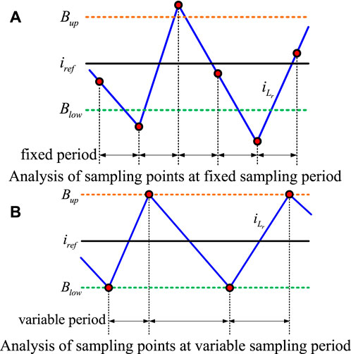
Figure 2. Analysis of sampling points at different sampling periods. (A) Analysis of sampling points at fixed sampling period, (B) Analysis of sampling points at variable sampling period.
As shown in Figure 2A, the red sampling points are inside the upper and lower boundary of the hysteresis bandwidth, which cannot trigger the converter to switch, and the sampling value is meaningless to the hysteresis control system; on the contrary, in Figure 2B, as each sampling current value is located on the upper and lower boundary of the bandwidth, it just makes the converter to switch, which is timely and effective. Due to the changes in the control reference, hysteresis bandwidth, and hardware parameters as well as external disturbances in the actual control system, the interval between sampling points or the sampling rate, is bound to change constantly if all sampling points are located on the bandwidth boundary of the hysteresis control, as shown in Figure 2B. Therefore, simply using the traditional ideal fixed sampling rate as shown in Figure 2A cannot meet the requirements of the actual sampling interval changes, which poses a challenge to reduce the sampling rate while ensuring the control accuracy. Therefore, it is important to study how to improve the effectiveness of digital hysteresis control and how to reduce the equivalent sampling rate.
According to the analysis, it can be known that: at each sampling point, the time required for the current to reach the next bandwidth intersection position can be deduced from the actual sampled current value, as well as the commanded current given by the algorithm, the upper and lower limits of the hysteresis bandwidth, and this time will be set as the next sampling period, then the ideal equivalent minimum sampling rate can be obtained in Eq. 1, as shown in Figure 3.
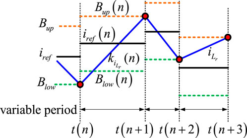
Figure 3. Schematic diagram of sampling time prediction at a minimum sampling rate.
Where
As can be seen from the above equation, the slope of the current has a critical impact on the sampling rate.
The following is an example of a Type I and Type T three-level inverter.
From the single-phase topology of the three-level inverter, the series equivalent resistance
In Eq. 2, the
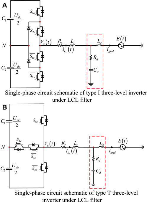
Figure 4. Single-phase circuit schematic of different type three-level inverter under LCL filter. (A) Single-phase circuit schematic of type I three-level inverter under LCL filter, (B) Single-phase circuit schematic of type T three-level inverter under LCL filter.
Then, according to the modulation law of the three-level switching state (Shen et al., 2011; Stefanutti and Mattavelli, 2006), the following Table 1 of switching states can be obtained.
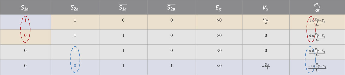
Table 1. Three-level converter switching state modulation relationship.
In Table 1,
From this, it can be seen that:
In Eq. 3,
Thus, the conventional sampling time prediction algorithm for digital hysteresis control of three-level converter can be obtained as follows:
where
Combined with the above analysis, it can be seen that the sampling moment predicted by the traditional digital hysteresis control algorithm is closely related to the inductance
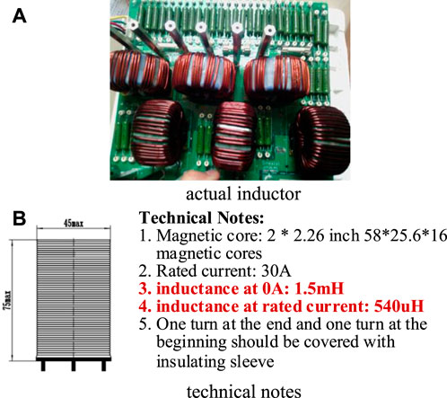
Figure 5. Actual inductor fabrication process. (A) actual inductor, (B) technical notes.
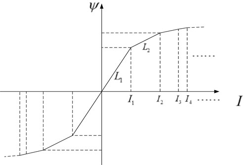
Figure 6. Variation curve of actual inductor flux versus inductance at different current.
From the previous analysis, it can be seen that how to accurately predict the sampling time when the actual inductor changes due to various current becomes a key step in reducing the equivalent sampling rate and improving the effectiveness of digital hysteresis control. Moreover, from the previous analysis, it is known that the predicted sampling rate varies due to a series of factors such as external disturbances in the sampling of controlled current, which inevitably cause changes in the control frequency (Ramchand et al., 2012; Shukla et al., 2011). Thus, it creates a big problem in the thermal loss of the converter, and the design of the LCL filter, especially the design of the inductance. Therefore, how to work with a relatively fixed switching frequency when both sampling time and inductance of the filer inductor change becomes a top priority. According to the literature (Davoodnezhad et al., 2014b), the bandwidth of the digital hysteresis control can be designed to change to ensure a fixed switching frequency when the sampling rate varies (Song et al., 2014; Zeng et al., 2004). Then, the bandwidth of the quasi-fixed frequency digital hysteresis control based on three-level converter with LCL filter can be expressed in Eq. 5 as follows:
Where
From the equation, it can be seen that the variation of the bandwidth in the hysteresis control can be inferred from the target expectation fixed switching frequency
So, assume:
Thus, when the sampling point is at the intersection of the current and the bandwidth, there is
By substituting Eqs (6), (7) into the previous Eq. 4, we can get:

After simplification, Eq. 8 can be expressed as:
Where
As can be seen from Eq. 9, the predicted sampling time is only related to the desired switching period and the control modulation index function
The previous equation is derived to be effective when the sampling point is just at the intersection of the current and the bandwidth, and after analysis, it is also effective when the current at the sampling moment exceeds the upper or the lower limits of the bandwidth, which can be corrected to:
where
However, the sampling point is likely to deviate from the bandwidth because of the delay in the sampling process, the inertia of the system, and the actual presence of delay in the PWM control. Thus, at some moments when the current value is less than the hysteresis bandwidth, a correction to the prediction Eq. 10 is required:
From Figure 7, it can be seen that:
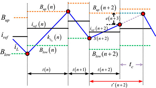
Figure 7. Schematic diagram of sampling time prediction correction.
when
then, the correction of sampling period is
Due to
Therefore,
According to Eq. 10 and Eq. 11, the online prediction algorithm based on inductance-free sampling time can be expressed as
Where:
In order to verify the above proposed control method, a simulation comparison analysis was conducted with a LCL type filter based on three-level neural-point-clamped inverter as an example, and the simulation parameters are listed in Table 2.
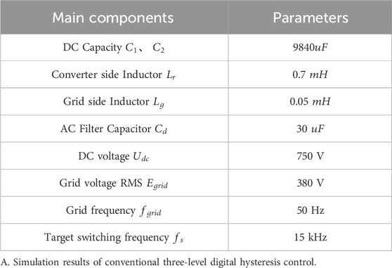
Table 2. Simulation main circuit parameters table.
The simulation results in Figure 8 show the three-phase grid voltage, three-phase inverter-side inductor current, three-level DC-side upper and lower bus capacitor voltage, and overall DC voltage ripple from top to bottom. It is evident that the traditional hysteresis control algorithm has a sudden change in inductor current at the zero-crossing point of the grid voltage, which causes the output waveform to change significantly, the total current harmonic distortion to increase, the hysteresis control error to exceed the bandwidth, and the control effect to be poor.
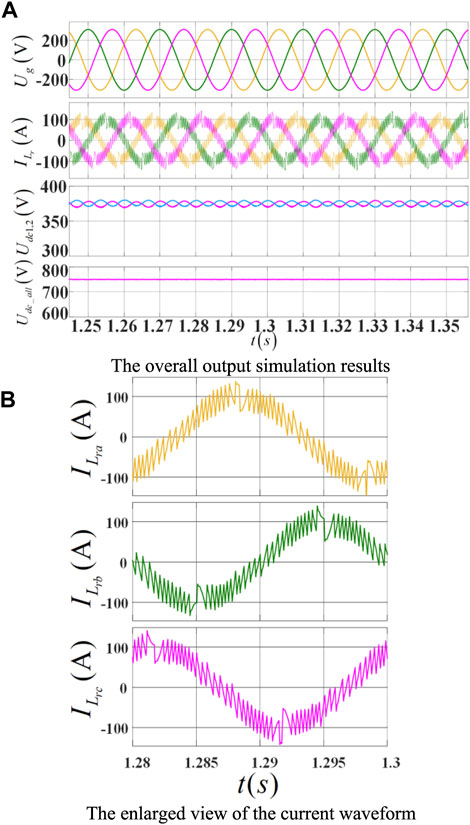
Figure 8. Inverter output simulation results under conventional digital hysteresis control. (A) The overall output simulation results, (B) The enlarged view of the current waveform.
From left to right in Figure 9, the results of the three-phase grid-side inductor current, the three-phase inverter-side inductor current, and the AC-side filter capacitors are shown in that order. As can be seen from Figure 9, due to the limitation of sampling rate and control frequency, the error current exists in a large range near the command current than the bandwidth, and the overall digital hysteresis control is less effective.
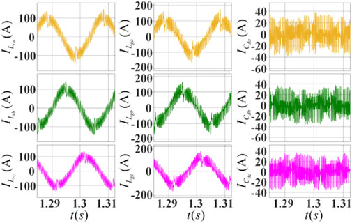
Figure 9. Waveform of LCL filter current of the three-level inverter under traditional digital hysteresis control algorithm.
In Figure 10, from top to bottom, the grid voltage, the inverter output current, the upper and lower bus capacitor voltages on the DC side of the three-level inverter and the total DC voltage simulation results are shown. It can be seen from the simulation results that the output inverter current is better sinusoidal, the control effect is significantly improved, there is no obvious change in output current waveform at the zero-crossing point of the grid, the error of the hysteresis current control is reduced and limited within the hysteresis band.
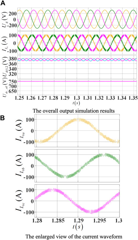
Figure 10. Inverter output results under the proposed digital hysteresis prediction algorithm. (A) The overall output simulation results, (B) The enlarged view of the current waveform.
From left to right in Figure 11, the results of the three-phase grid-side inductor current, the three-phase inverter-side inductor current, and the AC-side filter capacitors are shown in that order. As can be seen from Figure 11, the controlled inductor current is better sinusoidal, and the capacitor current is less ripple and there is a better control effect compared with the conventional digital hysteresis control method.
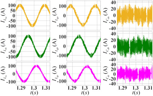
Figure 11. Inverter LCL filter current waveform under the proposed inductance-free digital hysteresis sampling time online prediction algorithm.
The simulation results in Figure 12 from top to bottom represent the reference current and the controlled current, the hysteresis bandwidth and the error current, the bandwidth and the counter needed to correct the period of sample time. From the simulation results, it can be seen that the controlled current is everywhere almost within the bandwidth and follows the reference current exactly with the proposed digital hysteresis sampling time online prediction algorithm. With the sample time correction algorithm, almost every sample point locates at the intersection of the bandwidth boundary exactly, and the current is controlled by the need sinusoidal reference.
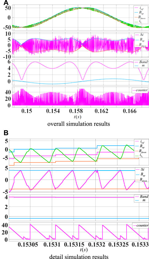
Figure 12. Simulation results of bandwidth versus error current and prediction time variation under the proposed digital hysteresis sampling time online prediction algorithm. (A) overall simulation results, (B) detail simulation results.
In order to further verify the theoretical feasibility of the proposed method and the accuracy of the simulation analysis, an experimental verification was conducted. The selected experimental equipment is a 100 kW type I three-level APF. The experimental parameters are shown in Table 3.
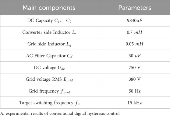
Table 3. Experimental main circuit parameters table.
The instrumentations used in the experimental setup in Figure 13 are list as follows: the grid-tie inverter is a 100 kW Type I three-level NPC inverter. The inductors are custom-made magnetic core inductors with 1.5 mH at empty load. The controller is used with a DSP 28335 control board with maximum 16 ADC channels and 12 PWM channels. The Oscilloscope is a ZLG 3024PLUS 4 channel scope with 300 MHz bandwidth. And the grid is connected through an isolated transformer with 500 kV A.
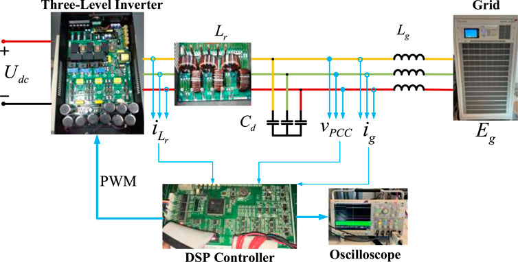
Figure 13. Configuration of the experimental setup.
The waveform in blue color in Figure 14 is the output inductor current and the red color is the inverter output PWM pulse voltage.
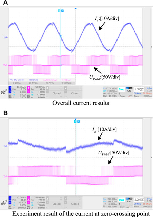
Figure 14. Output current and switch voltage of experiment results on conventional digital hysteresis control method. (A) Overall current results, (B) Experiment result of the current at zero-crossing point.
It is evident from the experimental results in Figure 14 that the conventional digital hysteresis control produces a poor output current waveform, with a noticeable current change at the grid zero-crossing point. As a result, there is little control effect and significant current distortion.
The switching process of the experimental waveform results in Figure 15 demonstrate how the sampled inductor current causes the traditional hysteresis control to be inaccurate. This results in frequent switching frequency adjustments and makes it challenging to adjust the output current within the hysteresis control bandwidth, both of which have an impact on the quality of the inverter’s final output current.
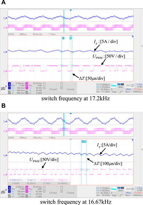
Figure 15. Different switching state of convention digital hysteresis control. (A) switch frequency at 17.2 kHz, (B) switch frequency at 16.67 kHz.
The above Figure 16 shows the results of the grid-side output waveform obtained by the proposed digital hysteresis control method without inductance using online time prediction. The blue one is the phase A grid-side current and the red one is the phase B grid-side current (the direction of the current transformer is reversed in the experiment). It can be seen that with this control method, the harmonic of the output current is obvious reduced, the distortion of the current is greatly reduced, and the quality of the output current is significantly controlled.

Figure 16. Output current waveform of proposed digital hysteresis control. (A) overall experiment results. (B) detail results in one grid frequency cycle.
The experimental findings of the inverter-side current switching procedure are displayed in Figure 17. In the experiment, the direction of the current transformer (shown in red) was reversed. The figure shows that there are no shocks in the current at the grid zero-crossing point, the overall inductor current is sinusoidal, and the inverter-side inductor current varies within the hysteresis bandwidth. The total power quality of the output current is efficiently managed and enhanced.
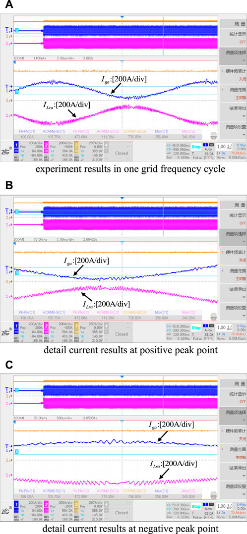
Figure 17. Inverter LCL filter current waveform under the proposed inductance-free digital hysteresis sampling time online prediction algorithm. (A) experiment results in one grid frequency cycle, (B) detail current results at positive peak point, (C) detail current results at negative peak point.
In this paper, a digital hysteresis control method for three-level inverter based on online prediction of sampling time without inductance is proposed. Through the sample time prediction and correction, the dependence on high sampling rate in traditional hysteresis control is reduced, while the accuracy is improved by keeping the error within the hysteresis band all the time. Furthermore, the impact of inductor parameter changing with different current is eliminated by cancelling the use of inductance during the control process. The effectiveness and robustness of the proposed control method are not only carried out by theoretical analysis and mathematical derivation, but also validated by simulation and experiment.
The raw data supporting the conclusion of this article will be made available by the authors, without undue reservation.
CS: Writing–original draft, Writing–review and editing. LD: Writing–review and editing. SS: Funding acquisition, Writing–review and editing. YX: Writing–review and editing. ZQ: Writing–review and editing. CP: Writing–review and editing.
The author(s) declare that financial support was received for the research, authorship, and/or publication of this article. This research was funded by the Natural Science of Shaanxi Province of China (No.2022JQ-344).
The authors declare that the research was conducted in the absence of any commercial or financial relationships that could be construed as a potential conflict of interest.
All claims expressed in this article are solely those of the authors and do not necessarily represent those of their affiliated organizations, or those of the publisher, the editors and the reviewers. Any product that may be evaluated in this article, or claim that may be made by its manufacturer, is not guaranteed or endorsed by the publisher.
Acuna, P., Mor´an, L., Rivera, M., Aguilera, R., Burgos, R., and Agelidis, V. G. (2015). A single-objective predictive control method for a multivariable single-phase three-level NPC converter-based active power filter. IEEE Trans. Ind. Electron. 62 (7), 4598–4607. doi:10.1109/tie.2015.2393556
Carl, N. H., Victor, S. P., and Chung, H. S. (2009). Constant-frequency hysteresis current control of grid-connected VSI without bandwidth control. IEEE Trans. Power Electron. 24 (11), 2484–2495. doi:10.1109/tpel.2009.2031804
Chavali, R. V., Dey, A., and Das, B. (2022). A hysteresis current controller PWM scheme applied to three-level NPC inverter for distributed generation interface. IEEE Trans. Power Electron. 37 (2), 1486–1495. doi:10.1109/TPEL.2021.3107618
Chen, Y., and Kang, Y. (2011). The variable-bandwidth hysteresis-modulation sliding-mode control for the PWM–PFM converters. IEEE Trans. Power Electron. 26 (10), 2727–2734. doi:10.1109/tpel.2011.2158852
Chen, Z., Luo, Y., and Chen, M. (2012). Control and performance of a cascaded shunt active power filter for aircraft electric power system. IEEE Trans. Ind. Electron. 59 (9), 3614–3623. doi:10.1109/tie.2011.2166231
Davoodnezhad, R., Holmes, D. G., and McGrath, B. P. (2014a). A novel three-level hysteresis current regulation strategy for three-phase three-level inverters. IEEE Trans. Power Electron. 29 (11), 6100–6109. doi:10.1109/tpel.2013.2295597
Davoodnezhad, R., Holmes, D. G., and McGrath, B. P. (2014b). “A fully digital hysteresis current controller for current regulation of grid connected PV inverters,” in presented at the IEEE 5th Int. Symp. IEEE Power Electronics for Distributed Generation Systems (PEDG), 2014 IEEE 5th International Symposium on, Galway, Ireland, Ireland, Jun. 2014 (IEEE), 1–8.
Gunter, S., and Fuchs, F. W. (2022). “Switching time prediction for digital hysteresis control for high frequency current in grid impedance measurement application,” in presented at the 16th Eur. Conf. Power Electronics and Applications (EPE’14-ECCE Europe), 2014 16th European Conference on, Lappeenranta, Finland, Finland, Aug. 26–28, 2014 (IEEE), 1–8.
He, J., Li, Y. W., Bosnjak, D., and Harris, B. (2013). Investigation and active damping of multiple resonances in a parallel-inverter-based microgrid. IEEE Trans. Power Electron. 28 (1), 234–246. doi:10.1109/tpel.2012.2195032
Hu, Y., Deng, Y., Liu, Q., and He, X. (2014). Asymmetry three-level gird-connected current hysteresis control with varying bus voltage and virtual oversample method. IEEE Trans. Power Electron. 29 (6), 3214–3222. doi:10.1109/tpel.2013.2272466
Jiao, Y., Lee, F. C., and Lu, S. (2014). Space vectormodulation for three-level NPC converter with neutral point voltage balance and switching loss reduction. IEEE Trans. Power Electron. 29 (10), 5579–5591. doi:10.1109/tpel.2013.2294274
Liu, F., and Maswood, A. I. (2006). A novel variable hysteresis band current con trol of three-phase three-level unity PF rectifier with constant switching frequency. IEEE Trans. Power Electron. 21 (6), 1727–1734. doi:10.1109/tpel.2006.882926
Malesani, L., Mattavelli, P., and Tomasin, P. (1997). Improved constant-frequency hysteresis current control of VSI inverters with simple feedforward band width prediction. IEEE Trans. Ind. Appl. 33 (5), 1194–1202. doi:10.1109/28.633796
Mohseni, M., and Islam, S. M. (2010). A new vector-based hysteresis current control scheme for three-phase PWM voltage-source inverters. IEEE Trans. Power Electron. 25 (9), 2299–2309. doi:10.1109/tpel.2010.2047270
Ramchand, R., Gopakumar, K. K., Patel, C., Sivakumar, K. K., Das, A., and Abu-Rub, H. (2012). Online computation of hysteresis boundary for constant switching frequency current-error space-vector-based hysteresis controller for VSI-fed IM drives. IEEE Trans. Power Electron. 27 (3), 1521–1529. doi:10.1109/tpel.2011.2120624
Shen, J., Schroder, S., Rosner, R., and El-Barbari, S. (2011). A comprehensive study of neutral-point self-balancing effect in neutral-point-clamped three-level inverters. IEEE Trans. Power Electron. 26 (11), 3084–3095. doi:10.1109/tpel.2011.2138161
Shukla, A., Ghosh, A., and Joshi, A. (2011). Hysteresis modulation of multilevel inverters. IEEE Trans. Power Electron. 26 (5), 1396–1409. doi:10.1109/tpel.2010.2082001
Song, W., Feng, X., and Smedley, K. M., (2014). “A carrier-based PWM strategy with the offset voltage injection for single-phase three-level neutral point clamped converters,” IEEE Trans. Power Electron., vol. 28, no. 3, pp. 1083–1095. doi:10.1109/tpel.2012.2210248
Stefanutti, W., and Mattavelli, P. (2006). Fully digital hysteresis modulation with switching-time prediction. IEEE Trans. Ind. Appl. 42 (3), 763–769. doi:10.1109/tia.2006.873665
Viswadev, R., Mudlapur, A., Ramana, V. V., Venkatesaperumal, B., and Mishra, S. (2020). A novel AC current sensorless hysteresis control for grid-tie inverters. IEEE Trans. Circuits Syst. II Express Briefs 67 (11), 2577–2581. doi:10.1109/tcsii.2019.2960289
Wang, X., Blaabjerg, F., and Chen, Z. (2014). Autonomous control of inverterinterfaced distributed generation units for harmonic current filtering and resonance damping in an islanded microgrid. IEEE Trans. Ind. Appl. 50 (1), 452–461. doi:10.1109/tia.2013.2268734
Wang, Y., and Li, R. (2013). Novel high-efficiency three-level stacked-neutralpoint-clamped grid-tied inverter. IEEE Trans. Ind. Electron. 60 (9), 3766–3774. doi:10.1109/tie.2012.2204712
Wang, Y., and Wang, F. (2013). Novel three-phase three-level-stacked neutral point clamped grid-tied solar inverter with a split phase controller. IEEE Trans. Power Electron. 28 (6), 2856–2866. doi:10.1109/tpel.2012.2226475
Keywords: three-level inverter, grid-tie inverter, digital hysteresis control, online prediction of sampling time, robustness of inductor parameters
Citation: Shulin C, Daxi L, Siyu S, Xinyu Y, Qiang Z and Peiyuan C (2024) A digital hysteresis control method for three-level grid-tie inverter based on online prediction of sampling time without inductance. Front. Energy Res. 12:1403346. doi: 10.3389/fenrg.2024.1403346
Received: 19 March 2024; Accepted: 12 April 2024;
Published: 10 May 2024.
Edited by:
Haitao Zhang, Xi’an Jiaotong University, ChinaCopyright © 2024 Shulin, Daxi, Siyu, Xinyu, Qiang and Peiyuan. This is an open-access article distributed under the terms of the Creative Commons Attribution License (CC BY). The use, distribution or reproduction in other forums is permitted, provided the original author(s) and the copyright owner(s) are credited and that the original publication in this journal is cited, in accordance with accepted academic practice. No use, distribution or reproduction is permitted which does not comply with these terms.
*Correspondence: Li Daxi, bGlkYXhpMTk4M0AxNjMuY29t
Disclaimer: All claims expressed in this article are solely those of the authors and do not necessarily represent those of their affiliated organizations, or those of the publisher, the editors and the reviewers. Any product that may be evaluated in this article or claim that may be made by its manufacturer is not guaranteed or endorsed by the publisher.
Research integrity at Frontiers
Learn more about the work of our research integrity team to safeguard the quality of each article we publish.