- 1College of Electrical and Power Engineering, Taiyuan University of Technology, Taiyuan, China
- 2State Nuclear Power Planning Design and Research Institute CO., Ltd, Beijing, China
In this article, a model predictive control (MPC) with common-mode voltage (CMV) suppression is proposed for single-phase cascaded H-bridge (CHB) inverters, which can also simultaneously achieve control objectives of grid-connected current tracking, voltages balancing of different H-bridge submodules on the DC-side and switching frequency reduction. To suppress high-frequency components of the common-mode voltage without additional switching devices, the algorithm proposed designs the predicted and reference values of the CMV and incorporates them in the cost function. At the same time, the capacitor voltages balancing control is integrated in the calculation of the optimal modulation function of the H-bridge, which reduces the complexity of control effectively. Besides, switching times of the MOSFETs are compared in two cycles. The cost function is constructed to represent comprehensive effect of the control. Finally, an experiment is performed on the hardware-in-the-loop experimental platform. The experimental results show that the proposed algorithm can offer a better voltage THD and reduce the times of switch action by nearly half while maintaining high-precision current tracking and maximum power point of photovoltaic modules, which alleviate the potential electromagnetic interference and cabling problem.
1 Introduction
At present, energy shortage and environmental pollution are becoming more and more serious. To change the traditional mode of economic growth with high energy consumption, most countries regard the development of low-carbon economy based on renewable energy as a focus issue (Zhang et al., 2018). Solar energy is one of the most promising future energy supplies for its high production capacity and low cost among various renewable energy sources, whose power generation has grown continuously at a rate of 20% in the past 20 years. It can be foreseen that the photovoltaic (PV) industry will have greater development space in the future (Ebrahimi et al., 2011).
Multilevel inverters have been widely used in high-voltage and high-power occasion to achieve electric energy conversion because of their advantages of high output waveform quality, low switching frequency, small harmonic distortion, and simple scalability (Vijeh et al., 2019; Poorfakhraei and Emadi, 2021; Salem et al., 2021). The cascaded H-bridge (CHB) has simpler structure and fewer switching devices among multilevel inverter topologies, without flying capacitors and clamp diodes. Each submodule of the CHB inverter is powered by the PV strings on the DC side, whose maximum power point tracking (MPPT) can be achieved independently (Yu et al., 2016). Therefore, the CHB inverter is more suitable for the PV system.
Multilevel inverters are available for decades, while new control strategies and modulation techniques are still being explored to improve the performance. To ensure the safe and stable operation of the system, multi objectives should be achieved simultaneously in the CHB inverter, such as suppressing CMV, increasing fault-tolerant ability, balancing floating capacitors, reducing switching frequency, etc.
One of the key objectives is that the balance of output power for PV modules in different H-bridge submodules when receive varied light intensity (Liu et al., 2021). Since the current of each submodule is constant, submodules with higher fundamental modulation voltage may be over modulation, which will increase the harmonic content of output voltage and affect the quality of grid-connected current, even cause oscillation and overcurrent (Rezaei et al., 2010). Existing control strategies for balancing floating capacitors were mainly based on improved MPPT (Eskandari et al., 2013), hybrid modulation technology (Miranbeigi and Iman-Eini, 2016; Zhao et al., 2018a), reactive power compensation (Rezaei et al., 2011; Liu et al., 2015; Wang et al., 2019), and harmonic compensation (Ko et al., 2017; Zhao et al., 2018b; Ko et al., 2018; Ye et al., 2019; Wang et al., 2020; Zhao et al., 2020). An improved MPPT strategy was proposed in (Eskandari et al., 2013), which increased the DC voltage of the over-modulated submodules and adjusted it to deviate from the maximum power point voltage for avoiding the occurrence of over modulation. However, the active power of the PV system was sacrificed, which against the advantages of the CHB inverter. Different hybrid modulation techniques were proposed to achieve power balancing of submodules to improve the DC voltage utilization of the inverter in (Miranbeigi and Iman-Eini, 2016; Zhao et al., 2018a). However, the fluctuation of DC voltage was increased, which is detrimental to efficiency of the PV system. The reactive power compensation angle was amplified in (Rezaei et al., 2011; Liu et al., 2015; Wang et al., 2019), which could reduce the fundamental amplitude of the output voltage and the probability of over modulation when the DC voltage remain constant. However, the power factor of the PV system was reduced while additional reactive power compensation equipment was required. A series of harmonic compensation methods were proposed in (Ko et al., 2017; Zhao et al., 2018b; Ko et al., 2018; Ye et al., 2019; Wang et al., 2020; Zhao et al., 2020), which could increase the utilization of DC voltage to 1.15 (Ko et al., 2017; Zhao et al., 2018b; Wang et al., 2020) and 1.273 (Ko et al., 2018; Ye et al., 2019; Zhao et al., 2020), respectively. However, the harmonic distribution of the output voltage for the CHB inverter was impacted and existing research lacked quantitative analysis.
The suppression of leakage current is also significant. There is a direct electrical connection between PV modules and the power grid without isolation transformer. Voltage of the parasitic capacitor between the ground and PV modules will change when inverter switches are activated, which result in the leakage current. The leakage current will cause electromagnetic interference and threaten personal safety (Ni et al., 2020). Therefore, suppression of the leakage current is essential for the PV system. In (Li et al., 2015; Chen et al., 2017), modified circuit topologies were applied to the PV system for suppressing leakage current, such as Heric, H5, H6, etc. However, the suppression effect of leakage current is limited. A modified cascaded H5 topology with inductors and capacitors on the AC side was proposed to achieve voltage clamping and division in (Guo and Jia, 2016), whose differential-mode leakage current was suppressed effectively. However, characteristics of output voltage were changed and circuit complexity was increased. Additional filtering inductors and capacitors were configured in each H-bridge in (Zhou and Li, 2014), which achieve better leakage current suppression effect. However, more power loss was caused by filters and the cost is higher. In (Selvamuthukumaran et al., 2015; Wang et al., 2018), a modified phase disposition pulse width modulation was proposed, which could keep the sum of the parasitic capacitor voltages constant and suppress the leakage current of the single-phase CHB inverter effectively. However, the modified modulation was only designed for the single-phase PV inverter with two H-bridges, making it difficult to extend to inverters with more submodules directly.
In recent years, model predictive control (MPC) has been widely used in the field of power electronic equipment control for intuitive control structure and ability of handling multiple control objectives simultaneously (Li et al., 2021). MPC predicts the future values of inverter for the next sampling cycle based on the discrete-time mathematic model. The optimal switching state of inverter is determined through a cost function, which is constructed of different forms of multivariable errors (Ni et al., 2022). The cost function represents the comprehensive control performance of inverter. The control and modulation of inverter are integrated into the cost function by MPC, which provide a powerful alternative to conventional proportional-integral (PI) and proportional-integral resonant (PIR) controllers. A control plane presented by the switching function coordinate was introduced in (He et al., 2023), in which only a subregion was selected to achieve control for reducing the execution time. However, it is only suitable for scenarios that do not require fast dynamic response. The MPC method is combined with the nonlinear sliding mode control in (He et al., 2022), so that fast dynamics can be achieved and control accuracy can be improved. A dual-layer MPC method for the CHB converter was proposed in (Xiao et al., 2023), in which fast output current control is achieved by optimal vector selection and dwell time calculation and the zero-sequence voltage candidate with the minimum predicted cluster voltages was injected to improved balancing speed.
In this article, a high-performance model predictive control is proposed to achieve the four control objectives simultaneously for the CHB-based PV inverter, in which existing overmodulation problem in the traditional control methods can also be avoided. Firstly, the grid-connected current of the PV inverter should be controlled precisely to maintain the power factor at 1. Secondly, the DC voltage of each H-bridge should be controlled independently so that the PV strings in different submodules can track their respective maximum power points. Besides, the high-frequency components of the CMV should be reduced to suppress the leakage current. Finally, the average switch frequency of the switching devices should be reduced for reducing the power loss.
The rest of this article is organized as follows. Section 2 introduces the topology and the operational principle of the CHB-based PV inverter. Section 3 describes the cost function, in which the predicted and reference values of controlled variables are also derived. Section 4 reports the experimental results. Finally, section 5 concludes the article.
2 System description
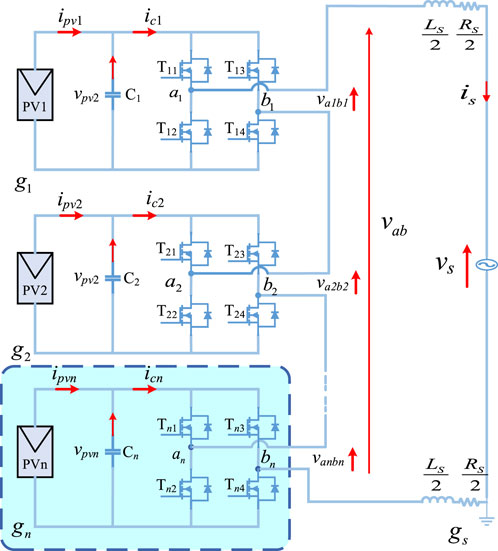
The single-phase CHB inverter is composed by two inductors and n H-bridge submodules connected in series, whose circuit topology is shown in Figure 1. Ls is the inductance of filtering inductors, and Rs is the parasitic resistance. Each H-bridge consists of the PV strings, a DC capacitor and four MOSFETs with anti-parallel diodes.
The number of PV strings and PV modules in each PV string depends on the rated power of the system, the voltage of grid, the rated voltage of PV modules and the number of H-bridges. Increasing number of the H-bridges will reduce the quantity of PV modules in each submodule and increase the levels of output voltage.
In order to avoid direct connection of H-bridge arm, the upper and lower MOSFETs are taken as opposite. For ease of analysis, Si1 and Si2 respectively denote the switching functions of the left and right arms of the ith H-bridge, which can be defined by (1).
The four switching states of H-bridge can output three different levels of voltage (+vpvi, 0 and - vpvi). Therefore, the total number of switching states can reach 4n when n H-bridges are cascaded together, 2n+1 levels of voltage can be output. Due to the increase of levels for output voltage, the waveform quality is also improved, and the grid-connection can also be achieved by inductor with smaller value.
Analyzing the circuit topology of the single-phase CHB inverter by the Kirchhoff’s voltage law (KVL), the continuous state-space mathematical model is given as:
where vs and is are the grid voltage and current, respectively. vab denotes the output voltage of the CHB inverter. vpvi and ipvi represent the DC capacitor voltage and output current of the PV strings, ici is the output current of submodule, where the subscript i indicates the order of the cascaded H-bridge.
The relationship between the voltage of capacitor vpvi on the DC side and the output voltage vaibi of H-bridge can be described by (3).
Eq. 2 model the dynamic behavior of the CHB inverter in the continuous state-space domain, in which the grid-current dynamics are controlled by the total generated output voltage of the inverter. On the other hand, equation of the capacitor voltage can be applied to balance the individual capacitor voltage of each H-bridge.
3 Proposed MPC with the CMV suppression
3.1 Design of the cost function
The MPC algorithm utilized the discrete character of the switching states in inverter to derive the discrete dynamic model of the system, which can relate the control objectives with the switching signals. Then, all switching state combinations are evaluated by using the cost function in the current control cycle. Finally, the switching state minimizing the cost function is selected to drive the MOSFETs. The essence of MPC algorithm is to predict the behavior of the system for each possible output voltage vector.
There are four control objectives should be achieved in the CHB-based PV inverter:
(1) Tracking grid-connected current.
(2) Balancing voltage of DC capacitors in different submodules.
(3) Suppressing the high-frequency components of the CMV.
(4) Reducing the switching frequency.
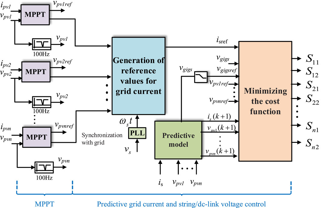
Figure 2 shows detailed control structure of the proposed MPC, in which the cost function should include variable quadratic errors between the predicted and reference values. In this way, the specific expression of the cost function can be represented by (4).
k denotes the current control cycle, while k+1 denotes the next control cycle. λ is the weighting factor, which is used for trading off among four objectives; its subscript i indicates the grid-connected current tracking, v indicates the capacitor voltages balancing, g indicates the suppression of the CMV, and c indicates the reduction of switching frequency.
The first part of the cost function is related to the current tracking performance; isref (k+1) and is(k+1) are the reference and predicted values of the grid-connected current. The second part represents DC voltage balance; vpviref (k+1) and vpvi(k+1) are the reference and predicted values of the capacitor voltage. The third part is involved with the CMV suppression. vgigsref (k+1) and vgigs(k+1) are the reference and predicted values of the CMV. The last part reflects the switching frequency reduction. nc(k+1) is the total number of switching actions in the next control cycle.
3.2 Calculation of predicted value
From the forward Euler method, the continuous state-space model can be expressed in the discrete-time domain. The prediction of the variable vectors can be obtained in the discrete mathematical model.
3.2.1 Prediction of the grid-connected current
Based on the load current model in (2), the grid-connected current in the next control cycle, is(k+1), can be predicted as (5).
TS is the control cycle of MPC. vs(k) and is(k) should be obtained by measuring and sampling.
According to Equation 3, vab(k) can be calculated by (6).
3.2.2 Prediction of DC capacitor voltage
The prediction of DC capacitor voltage vpvi(k+1) of the ith H-bridge can be calculated as (7).
ici(k) can be calculated by (8).
3.2.3 Prediction of the switching action times
The total number of switching actions nc(k+1) can be obtained by comparing the differences of switching state for the CHB inverter between the current and next control cycles, as shown in (9). It can be inferred that regardless of whether the MOSFET is turned on or off, the switching action times will be calculated.
3.2.4 Prediction of the CMV
There is a direct electrical connection between PV modules and the power grid without transformer isolation, which will occur leakage current on the parasitic capacitor between PV modules and the ground. The leakage current will reduce system reliability, threaten personal safety, and generate electromagnetic interference. To reduce the leakage current and avoid using isolation transformer, vgigs should be maintained lower, which is the voltage between the negative input terminal (gi) of the ith submodule and the grounding terminal (gs). It can be calculated as (10).
3.3 Calculation of reference value
3.3.1 Calculation of grid-connected current reference value
The reference value isref (k+1) of grid-connected current can be obtained based on the principle of power balance on the AC and DC sides. The DC power is determined by PV modules and can be obtained through the MPPT algorithm in the ith submodule, which is denoted by Ppviref. Therefore, if all PV modules in submodules operate at maximum power points respectively, the reference value of the grid current in the next control cycle should be calculated as (11).
vs,rms(k) is the effective value of the grid voltage, vs(k) is the instantaneous value of the grid voltage.
3.3.2 Calculation of DC capacitor voltage reference value
The reference value vpviref (k+1) of DC capacitor voltage is the operating voltage of the PV modules at maximum power point, which is obtained by the MPPT.
Specifically, the operating voltage of the PV modules at maximum power point can be obtained by the MPPT in the first H-bridge, which is also the reference value of the DC capacitor voltage, and can be denoted by vpv1ref (k+1). According to the same method, the reference value of DC capacitor voltage for the second, the third, …, the nth H-bridge submodule can be obtained and denoted by vpv2ref (k+1), vpv3ref (k+1), …, vpvnref (k+1), respectively.
3.3.3 Calculation of the CMV reference value
The CMV contains a large number of harmonic components, which will generate displacement current. Therefore, a digital first-order low-pass filter is designed to filter out the high-frequency harmonic components. Based on the designed filter, the reference value vgigsref (k+1) of the CMV can be obtained, which is substituted into the cost function g together with vgigs(k+1) to suppress the CMV. vgigsref (k+1) can be calculated based on the predicted reference vgigs(k+1) of CMV in the next control cycle and the filtered CMV vgigsref (k+1) in the current control cycle, shown as:
where α = 2πfTD/(1+2πfTD); f is the cut-off frequency of the designed first-order low-pass filter; and TD is the sampling period of the digital controller.
3.4 Controller design procedure
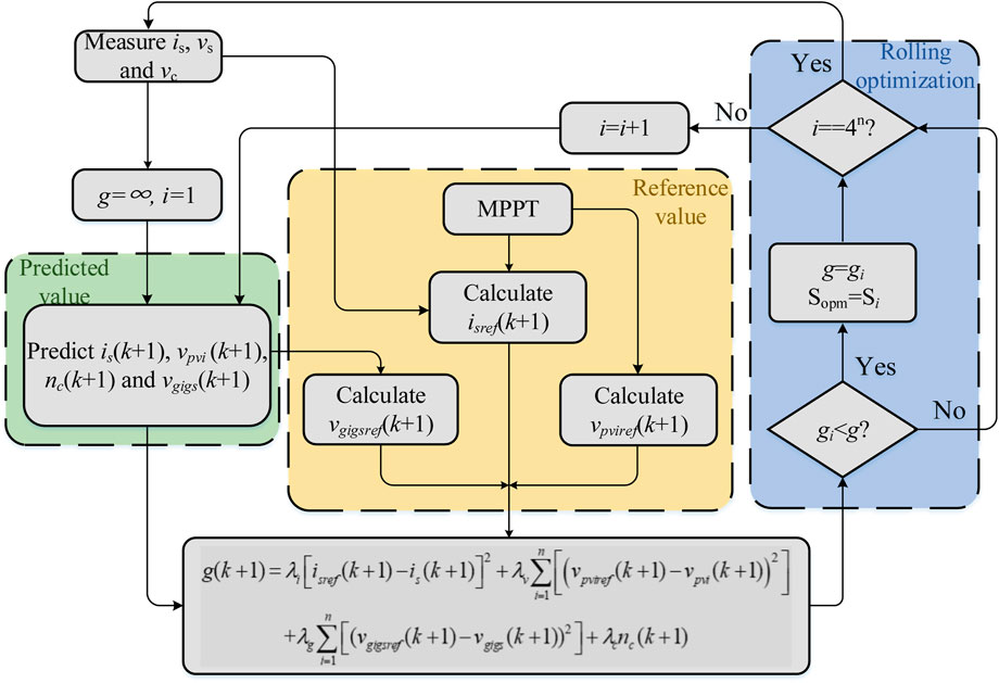
The flowchart of the proposed MPC is shown in Figure 3. The design procedure of the proposed method can be summarized as the following steps:
(1) Measure the required circuit parameters of the designed method.
(2) Define matrix S for all the possible switching states.
(3) Initialize the controller state and set the initial value for the cost function g.
(4) Calculate predicted values of variables using (5), 7, 9, and 10.
(5) Obtain reference values using (11), 12.
(6) Select the optimal switching state Sopm through rolling optimization using the cost function g in (4).
4 Experimental results
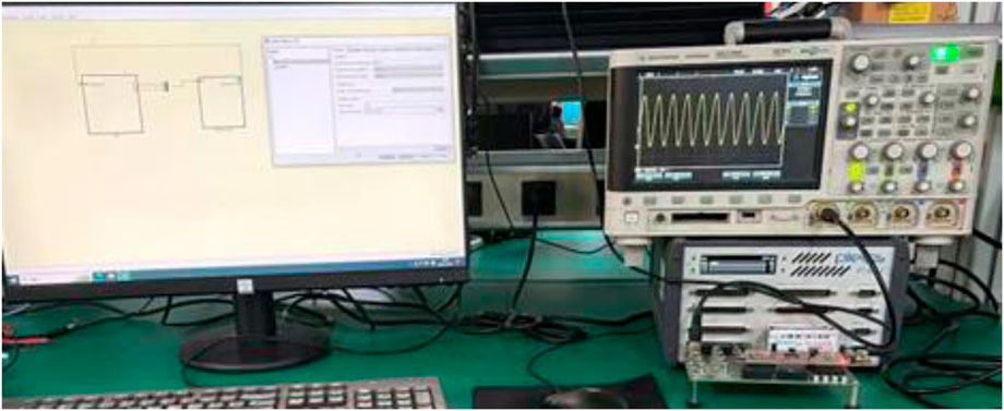
A semi physical experimental platform as shown in Figure 4 is constructed to verify the feasibility and effectiveness of the proposed MPC with high-frequency CMV suppression in this paper. The control algorithm is implemented in the TMS320F28069 digital controller, while the main circuit is structured by building a simulation model on the RT BOX platform.
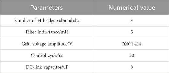
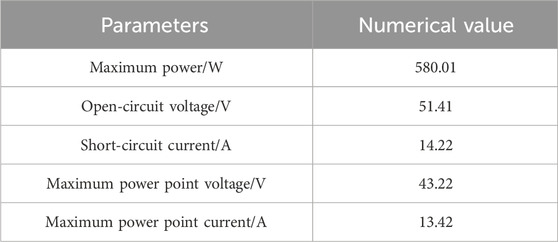
Table 1 shows the parameters of the main circuit, which consists of three H-bridge submodules, each submodule is constituted of three PV modules connected in series on the DC side. The main parameters of each PV module are shown in Table 2. The maximum power point voltage of the PV module is 43.22 V, which also means that the DC voltage of each H-bridge is 129.66 V at the maximum power point.
To validate the steady-state and dynamic performance of the proposed MPC to various grid-connected conditions on a seven-level CHB inverter, two groups of experiments are performed, whose sample time Ts is fixed at 50 μ Before t = 0.5 s, the weighting factor λi is set to 5, λv is set to 10, λg and λc are set to 0. After t = 0.5 s, λg and λc are set to 1e−4 and 0.1, respectively. Therefore, the high-frequency components suppression of the CMV and switching frequency reduction are not enabled before 0.5 s. The experimental results are shown in Figures 5, 6 at the effective value for grid voltage of 220 v.
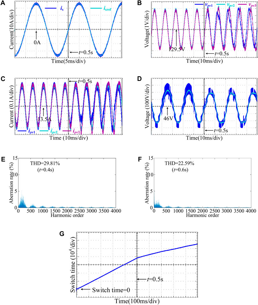
Figure 5. Experimental results under power balance of three submodules (A) Waveforms of is and isref. (B) Waveforms of vpv1, vpv2, vpv3. (C) Waveforms of ipv1, ipv2, ipv3. (D) Waveforms of vg1gs and vg1gsref. (E) The spectrum of vg1gs at t = 0.4 s. (F) The spectrum of vg1gs at t = 0.6 s. (G) Waveform of nc.
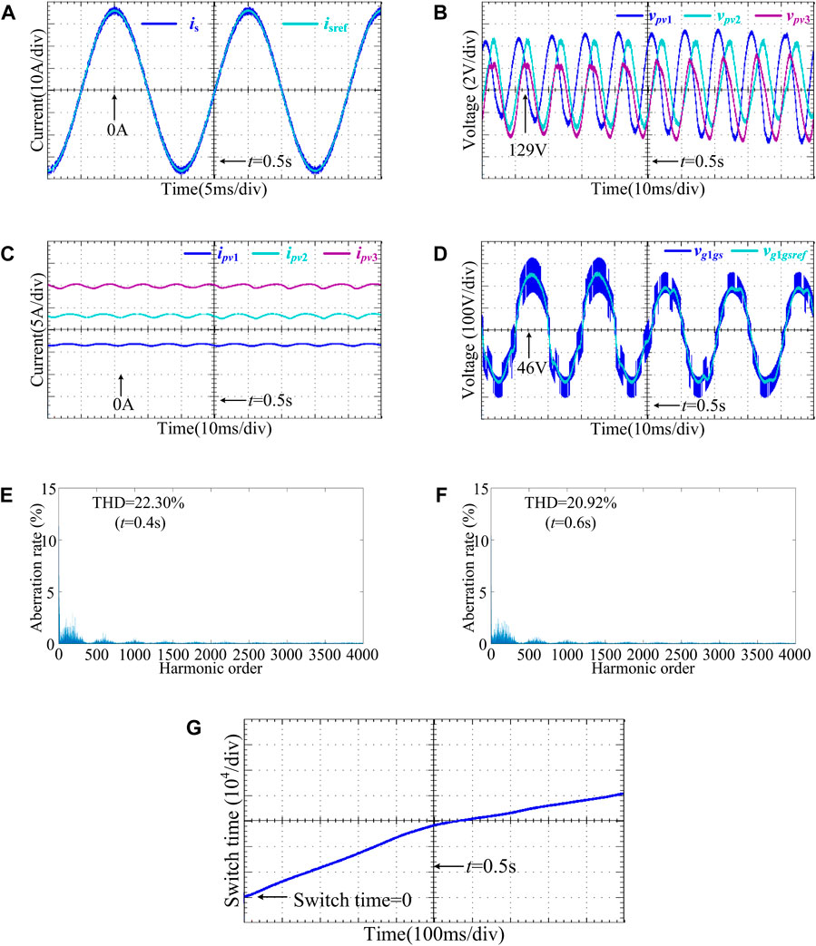
Figure 6. Experimental results under power imbalance of three submodules (A) Waveforms of is and isref. (B) Waveforms of vpv1, vpv2, vpv3. (C) Waveforms of ipv1, ipv2, ipv3. (D) Waveforms of vg1gs and vg1gsref. (E) The spectrum of vg1gs at t = 0.4 s. (F) The spectrum of vg1gs at t = 0.6 s. (G) Waveform of nc.
4.1 Power balance condition
The experimental results in Figure 5 are obtained under power balance condition of three submodules, in which the light intensity of the PV modules is all set to 1000 W/m2, and their ambient temperatures are set to 25°C. The rated power of PV strings on the DC side for each submodule are 1740 W. According to Equation 11, the effective value of the grid-connected current reference value is 142.43 A.
Figure 5A shows the waveforms of is and isref, in which the grid-connected output current is very smooth. Even after adding CMV suppression and switching frequency reduction at 0.5s, the grid-connected current still maintains high-precision tracking for reference value without significant current fluctuations.
Figures 5B,C shows the waveforms of vpvi and ipvi, respectively. The DC voltages and currents of the three submodules are almost consistent, the voltages on the DC side reach the operating voltage of 129.66 V at the maximum power point of the PV strings. The submodules can output 1640.82 W at the maximum power point. After 0.5 s, vpvi and ipvi occur a fluctuation of around 1V–3 V and 0.5 A, respectively, resulting in a decrease in consistency. Then, they tend to stabilize again after 30 ms, and overall balance of the system is still maintained. The PV strings are still operating near the maximum power point, outputting 1635.46 W. The efficiency of system is 94.3%.
As is shown in Figure 5D for vg1gs and vg1gsref, the peak value of vg1gs is larger initially, about 1700v; in addition, the high-frequency components of vg1gs account for a large proportion, with a THD of 29.81% at 0.4s. After suppressing CMV at 0.5s, the high-frequency components of vg1gs significantly decreased, in which THD has already dropped to 22.59% at 0.6s and the peak value has dropped at 1300v approximately.
Figure 5E expresses the waveform of nc, which indicates that the average switching frequency of the CHB inverter. Before 0.5s, the average switching times of the CHB inverter is 1.9×10⁵/s, after reducing switching frequency, the number of average switching times is decreased by 52.63%, only need to be activated 0.9×10⁵/s. The unnecessary multiple voltage level jumps are reduced to a large extent.
Besides, we conducted efficiency analysis on submodules with light intensities of 300 W/m2, 600 W/m2, 900 W/m2, 1200 W/m2 and 1500 W/m2 separately, in which the output power of the system is all around the maximum power point, with an average efficiency of 94.53%.
4.2 Power imbalance condition
The experimental results in Figure 6 are obtained under power imbalance condition of three submodules at 25°C, in which the light intensity of the PV modules is set to 500W/m2, 1000 W/m2 and 1500 W/m2. The main experimental condition is the same as the first group experiment. The rated power of PV strings on the DC side for each submodule are 872.7 W, 1740 W and 2572 W, respectively. The effective value of the grid-connected current reference value is 141.58 A.
Figure 6A shows the waveforms of is and isref under power imbalance condition, in which the grid-connected current always maintains high-precision tracking for reference value without significant current fluctuations around 0.5s.
Figures 6B,C shows the waveforms of vpvi and ipvi under power imbalance condition, respectively. The DC voltages and currents of the three submodules are almost different, reaching their operating voltage at maximum power points:128.05 V, 129.66 V, and 129.92 V. The submodules output the maximum power. After 0.5 s, the distribution of vpvi and ipvi are almost identical to 0.5s ago, without falling or rising sharply. This means that the addition of new control objectives makes no difference to the original voltage balance of the system, and the PV strings of each submodule can still operate near respective maximum power point under power imbalance condition.
As is shown in Figure 6D for vg1gs and vg1gsref under power imbalance condition, the peak value of vg1gs is around 1700v; in addition, the high-frequency components of vg1gs account for a large proportion, with a THD of 22.30% at 0.4s. After suppressing CMV, the THD of vg1gs has already dropped to 20.92% at 0.6s and the peak value has dropped at 1300v approximately.
Figure 6E expresses the waveform of nc under power imbalance condition. Before 0.5s, the average switching times of the CHB inverter is 1.9×10⁵/s, after reducing switching frequency, the number of average switching times has been decreased by 63.16%, need to be activated 0.7×10⁵/s.
It can be concluded that, under the imbalanced power condition, the proposed method maintains high precision grid-connected current tracking control, suppresses the high-frequency components of the CMV effectively, and reduces the average switching frequency of the CHB inverter significantly. At the same time, independent control of the DC capacitor voltages is achieved for each submodule. Therefore, the PV modules in different submodules can respectively operate at their own maximum power points, which improves efficiency of the PV system.
4.3 Comparison with traditional methods
The experimental results show that the proposed algorithm is applicable to various grid-connected operating condition, which proves the feasibility and effectiveness of the proposed algorithm. Therefore, the comparisons between the proposed method and various strategies are shown in Tables 3 and 4 to better demonstrate the advantages of the proposed method.
Compared with existing methods, all control objectives of the proposed method are achieved through predictive models and cost function, without need of linear model for the system. Based on this, four control objectives previously mentioned are achieved. In addition, the reference values of grid-connected current and capacitor voltages are calculated according to the MPPT algorithm, which further improves the power generation efficiency of the system with a higher accuracy.
5 Conclusion
In this article, the proposed algorithm was adopted to select the global optimal modulation function of the CHB inverter in the current predictive control cycle. Four control objectives are simultaneously achieved based on the cost function of proposed MPC. The performance of the proposed method is verified on a controller hardware-in-the-loop experimental platform. The experimental results have shown that the proposed MPC can track the grid-connected current accurately, the PV modules in different submodules can also independently operate at their own maximum power points. Meanwhile, the high-frequency components of the CMV are significantly suppressed, and a lower average switching frequency is also achieved. However, if the proposed method is extended to CHB-based PV inverter containing numerous submodules, the required computational complexity will be a challenge for general digital controllers. Future research should be focused on reducing the computational complexity to improve the availability of the proposed algorithm, and we will also try to apply this method to other multi-level cascaded circuit topologies.
Data availability statement
The raw data supporting the conclusion of this article will be made available by the authors, without undue reservation.
Author contributions
XW: Conceptualization, Investigation, Writing–original draft, Methodology. WT: Data curation, Formal Analysis, Software, Writing–review and editing. XF: Formal Analysis, Project administration, Writing–review and editing.
Funding
The author(s) declare that financial support was received for the research, authorship, and/or publication of this article. Research on open-circuit fault diagnosis and seamless fault-tolerant control of multiple devices in modular multilevel digital power amplifiers: 202203021212210; Research on Key technologies and demonstrations of low-voltage DC power electronic converters based on SiC devices Access: 202102060301012; Research on Control Methods and Fault Tolerance of Multilevel Electronic Transformers for PV Access: 042300034204.
Conflict of interest
Author XF was employed by State Nuclear Power Planning Design and Research Institute CO., Ltd.
The remaining authors declare that the research was conducted in the absence of any commercial or financial relationships that could be construed as a potential conflict of interest.
Publisher’s note
All claims expressed in this article are solely those of the authors and do not necessarily represent those of their affiliated organizations, or those of the publisher, the editors and the reviewers. Any product that may be evaluated in this article, or claim that may be made by its manufacturer, is not guaranteed or endorsed by the publisher.
References
Chen, K., Huang, Z., Hang, L., Xie, X., Han, Q., Lu, Q., et al. (2017). “Cascaded iH6 multilevel inverter with leakage current reduction for transformerless grid-connected photovoltaic system,” in 2017 IEEE 12th International Conference on Power Electronics and Drive Systems (PEDS), Honolulu, HI, USA, 12-15 December 2017, 613–617.
Ebrahimi, J., Babaei, E., and Gharehpetian, G. B. (2011). A new topology of cascaded multilevel converters with reduced number of components for high-voltage applications. IEEE Trans. Power Electron. 26 (11), 3109–3118. doi:10.1109/tpel.2011.2148177
Eskandari, V. J., Iman-Eini, H., and Yadollahi, M. (2013). “Stable operation of grid connected Cascaded H-Bridge inverter under unbalanced insolation conditions,” in 2013 3rd International Conference on Electric Power and Energy Conversion Systems, Istanbul, Turkey, 02-04 October 2013, 1–6.
Guo, X., and Jia, X. (2016). Hardware-based cascaded topology and modulation strategy with leakage current reduction for transformerless PV systems. IEEE Trans. Industrial Electron. 63 (12), 7823–7832. doi:10.1109/tie.2016.2607163
He, T., Wu, M., Aguilera, R. P., Lu, D. D.-C., Liu, Q., and Vazquez, S. (2023). Low computational burden model predictive control for single-phase cascaded H-bridge converters without weighting factor. IEEE Trans. Industrial Electron. 70 (3), 2396–2406. doi:10.1109/tie.2022.3167133
He, T., Wu, M., Lu, D. D.-C., Song, K., and Zhu, J. (2022). Model predictive sliding control for cascaded H-bridge multilevel converters with dynamic current reference tracking. IEEE J. Emerg. Sel. Top. Power Electron. 10 (2), 1409–1421. doi:10.1109/jestpe.2021.3053300
Ko, Y., Andresen, M., Buticchi, G., and Liserre, M. (2017). Power routing for cascaded H-bridge converters. IEEE Trans. Power Electron. 32 (12), 9435–9446. doi:10.1109/tpel.2017.2658182
Ko, Y., Andresen, M., Buticchi, G., and Liserre, M. (2018). Thermally compensated discontinuous modulation strategy for cascaded H-bridge converters. IEEE Trans. Power Electron. 33 (3), 2704–2713. doi:10.1109/tpel.2017.2694455
Li, W., Gu, Y., Luo, H., Cui, W., He, X., and Xia, C. (2015). Topology review and derivation methodology of single-phase transformerless photovoltaic inverters for leakage current suppression. IEEE Trans. Industrial Electron. 62 (7), 4537–4551. doi:10.1109/tie.2015.2399278
Li, Y., Diao, F., and Zhao, Y. (2021). Simplified two-stage model predictive control for a hybrid multilevel converter with floating H-bridge. IEEE Trans. Power Electron. 36 (4), 4839–4850. doi:10.1109/tpel.2020.3018956
Liu, B., Song, W., Li, Y., and Zhan, B. (2021). Performance improvement of DC capacitor voltage balancing control for cascaded H-bridge multilevel converters. IEEE Trans. Power Electron. 36 (3), 3354–3366. doi:10.1109/tpel.2020.3012540
Liu, L., Li, H., Xue, Y., and Liu, W. (2015). Reactive power compensation and optimization strategy for grid-interactive cascaded photovoltaic systems. IEEE Trans. Power Electron. 30 (1), 188–202. doi:10.1109/tpel.2014.2333004
Miranbeigi, M., and Iman-Eini, H. (2016). Hybrid modulation technique for grid-connected cascaded photovoltaic systems. IEEE Trans. Industrial Electron. 63 (12), 7843–7853. doi:10.1109/tie.2016.2580122
Ni, Z., Abuelnaga, A., and Narimani, M. (2020). A novel high-performance predictive control formulation for multilevel inverters. IEEE Trans. Power Electron. 35 (11), 11533–11543. doi:10.1109/tpel.2020.2987828
Ni, Z., Abuelnaga, A. H., Pan, Y., Elezab, A., Zayed, O., Narimani, M., et al. (2022). A new MPC formulation based on suboptimal voltage vectors for multilevel inverters. IEEE J. Emerg. Sel. Top. Power Electron. 10 (6), 7261–7270. doi:10.1109/jestpe.2022.3200063
Poorfakhraei, M. N., and Emadi, A. (2021). A review of modulation and control techniques for multilevel inverters in traction applications. IEEE Access 9, 24187–24204. doi:10.1109/access.2021.3056612
Rezaei, M. A., Farhangi, S., and Iman-Eini, H. (2010). “Extending the operating range of cascaded H-bridge based multilevel rectifier under unbalanced load conditions,” in 2010 IEEE International Conference on Power and Energy, Kuala Lumpur, Malaysia, 29 November 2010 - 01 December 2010, 780–785.
Rezaei, M. A., Farhangi, S., and Iman-Eini, H. (2011). “Enhancing the reliability of single-phase CHB-based grid-connected photovoltaic energy systems,” in 2011 2nd Power Electronics, Drive Systems and Technologies Conference, Tehran, Iran, 16-17 February 2011, 117–122.
Salem, H., Robbersmyr, K. G., Norambuena, M., and Rodriguez, J. (2021). Voltage source multilevel inverters with reduced device count: topological review and novel comparative factors. IEEE Trans. Power Electron. 36 (3), 2720–2747. doi:10.1109/tpel.2020.3011908
Selvamuthukumaran, R., Garg, A., and Gupta, R. (2015). Hybrid multicarrier modulation to reduce leakage current in a transformerless cascaded multilevel inverter for photovoltaic systems. IEEE Trans. Power Electron. 30 (4), 1779–1783. doi:10.1109/tpel.2014.2345501
Vijeh, M., Rezanejad, M., Samadaei, E., and Bertilsson, K. (2019). A general review of multilevel inverters based on main submodules: structural point of view. IEEE Trans. Power Electron. 34 (10), 9479–9502. doi:10.1109/tpel.2018.2890649
Wang, C., Zhang, K., Xiong, J., Xue, Y., and Liu, W. (2019). A coordinated compensation strategy for module mismatch of CHB-PV systems based on improved LS-PWM and reactive power injection. IEEE Trans. Industrial Electron. 66 (4), 2825–2836. doi:10.1109/tie.2018.2842789
Wang, F., Li, Z., Do, H. T., and Zhang, D. (2018). A modified phase disposition pulse width modulation to suppress the leakage current for the transformerless cascaded H-bridge inverters. IEEE Trans. Industrial Electron. 65 (2), 1281–1289. doi:10.1109/tie.2017.2733488
Wang, M., Zhang, X., Zhao, T., Ma, M., Hu, Y., Wang, F., et al. (2020). Harmonic compensation strategy for single-phase cascaded H-bridge PV inverter under unbalanced power conditions. IEEE Trans. Industrial Electron. 67 (12), 10474–10484. doi:10.1109/tie.2019.2962461
Xiao, Q., Jia, H., Tang, Y., Jin, Y., Mu, Y., Teodorescu, R., et al. (2023). Dual-layer modulated model predictive control scheme for the cascaded H-bridge converter. IEEE Trans. Industrial Electron. 70 (10), 9751–9763. doi:10.1109/tie.2022.3224185
Ye, M., Ren, W., Chen, L., Wei, Q., Song, G., and Li, S. (2019). Research on power-balance control strategy of CHB multilevel inverter based on TPWM. IEEE Access 7, 157226–157240. doi:10.1109/access.2019.2950064
Yu, Y., Konstantinou, G., Hredzak, B., and Agelidis, V. G. (2016). Power balance of cascaded H-bridge multilevel converters for large-scale photovoltaic integration. IEEE Trans. Power Electron. 31 (1), 292–303. doi:10.1109/tpel.2015.2406315
Zhang, X., Zhao, T., Mao, W., Tan, D., and Chang, L. (2018). Multilevel inverters for grid-connected photovoltaic applications: examining emerging trends. IEEE Power Electron. Mag. 5 (4), 32–41. doi:10.1109/mpel.2018.2874509
Zhao, T., Zhang, X., Mao, W., Wang, F., Xu, J., and Gu, Y. (2018a). A modified hybrid modulation strategy for suppressing DC voltage fluctuation of cascaded H-bridge photovoltaic inverter. IEEE Trans. Industrial Electron. 65 (5), 3932–3941. doi:10.1109/tie.2017.2758758
Zhao, T., Zhang, X., Mao, W., Wang, F., Xu, J., Gu, Y., et al. (2018b). An optimized third harmonic compensation strategy for single-phase cascaded H-bridge photovoltaic inverter. IEEE Trans. Industrial Electron. 65 (11), 8635–8645. doi:10.1109/tie.2018.2813960
Zhao, T., Zhang, X., Mao, W., Wang, M., Wang, F., Wang, X., et al. (2020). Harmonic compensation strategy for extending the operating range of cascaded H-bridge PV inverter. IEEE J. Emerg. Sel. Top. Power Electron. 8 (2), 1341–1350. doi:10.1109/jestpe.2019.2895113
Keywords: model predictive control (MPC), photovoltaic system, cascaded H-bridge (CHB), common-mode voltage (CMV), maximum power point tracking (MPPT)
Citation: Wei X, Tao W and Fu X (2024) Model predictive control for single-phase cascaded H-bridge photovoltaic inverter system considering common-mode voltage suppression. Front. Energy Res. 12:1371239. doi: 10.3389/fenrg.2024.1371239
Received: 16 January 2024; Accepted: 17 April 2024;
Published: 07 August 2024.
Edited by:
Enrico Maria Vitucci, University of Bologna, ItalyReviewed by:
Mohamed Salem, University of Science Malaysia (USM), MalaysiaKhaled Obaideen, University of Sharjah, United Arab Emirates
Copyright © 2024 Wei, Tao and Fu. This is an open-access article distributed under the terms of the Creative Commons Attribution License (CC BY). The use, distribution or reproduction in other forums is permitted, provided the original author(s) and the copyright owner(s) are credited and that the original publication in this journal is cited, in accordance with accepted academic practice. No use, distribution or reproduction is permitted which does not comply with these terms.
*Correspondence: Wanyu Tao, MjQ1Mjg3MjIwNUBxcS5jb20=
 Xinwei Wei
 Wanyu Tao
 Xunbo Fu2