 Wang Bin
 Jia Tao1,2
 Tan Peng
- 1CNPC Engineering Technology R&D Company Limited, Beijing, China
- 2National Engineering Research Center for Oil and Gas Drilling and Completion Technology, Beijing, China
The study of fracture propagation in heterogeneous shale is a crucial prerequisite for the investigation of heterogeneous cluster and perforation parameters optimization. In this paper, we conduct a physical simulation fracturing experiment on heterogeneous shale to investigate the effects of various influencing factors, such as shale bedding, near-wellbore fractures, lithological changes, and the presence of fractures surrounding the perforation hole, on fracture propagation law and morphology. Our research demonstrates that during shale fracturing, shear dislocation typically occurs between layers, resulting in the separation of different layer planes. The main fracture primarily propagates through layers in a stepped manner. The presence of sandstone in heterogeneous shale significantly impedes fracturing fractures, causing significant distortion and deviation. As the scale of natural fractures increases, it tends to cause the fracturing fracture to twist and change direction. The natural fractures network can also lead to the distortion of fracturing fractures, albeit to a lesser extent than large-scale natural fractures. The presence of micro fractures parallel to the perforation axis surrounding the perforation hole enhances the ability of the main fracturing fractures to pass through natural fractures.
1 Introduction
In recent years, with the concepts of clean energy and low-carbon living becoming increasingly popular worldwide, sustainable development of energy and economy is more and more important. The more efficient development of fracturing in unconventional oil and gas resources is one of the key technologies for achieving sustainable development in energy, society, and economy.
In order to achieve the goal of more efficient fracturing in unconventional oil and gas resources, studying the fracture propagation in heterogeneous shale is very important (YEW and CHIOU, 1983; WANG and CLIFTON, 1991; Bunger et al., 2011; DONTSOV, 2022; MA et al., 2022). Conducting physical fracturing experiments is the most effective way to study the mechanism and law of fracture propagation (XIAO et al., 2005; GE and GHASSEMI, 2008; HUANG et al., 2019; TAN et al., 2020). To date, scholars worldwide have conducted a significant amount of research on the expansion of hydraulic fractures in the rational medium of heterogeneous layers (WARPINSKI et al., 1982; CHUPRAKOV and PRIOUL, 2015; DONTSOV and PEIRCE, 2015; Liu and Valkó, 2015). However, previous research results revealed that the focus of these studies on studying fracture expansion in heterogeneous shale is primarily on the establishing the criteria of the fracture propagation through the shale layers and the calculation of the corresponding fracture height and length (SHAFFER et al., 1984; TAN et al., 2021; HUANG et al., 2023a; HUANG et al., 2023b), lacking studying the effect of the multiple influencing factors of lithological changes, natural fractures and existence of micro fractures around the perforation hole, etc., on the propagation law and shape of fractures in shale rock (NIE et al., 2021; SHI et al., 2023; TAN et al., 2023).
To address the shortcomings of previous studies, this paper presents a necessary heterogeneous shale physical simulation fracturing experiment to explore the effect of influencing factors of shale bedding, near well-bore fractures, lithological changes and the existence of fractures around the perforation hole on the fracture propagation law and morphology.
2 Experimental preparation
Before the physical simulation fracturing experiment, cement mortar is used to simulate the heterogeneous bedding shale rock sample. Each rock sample is composed of four layers, the physical parameters of each layer can be adjusted according to the experiment purpose, so as to explore the effect of influencing factors of shale bedding, near well-bore fractures, lithological changes and the existence of fractures around the perforation hole on the fracture propagation law and morphology. Each rock sample features a central perforation hole. It is also worth noting that, in order to minimize the influence of geostress differences on fracture propagation, the geostress difference is set to 0.
2.1 Experimental preparation
The preparation process for the simulated heterogeneous shale rock sample is illustrated in Figure 1. Each rock sample is cylindrical, with a diameter of 180 mm. Each rock sample consists of four layers, with each layer having a thickness of 30 mm and a total thickness of 120 mm. The cement mortar is poured in layers, starting from the bottom and moving towards the top. After each layer is poured, it would be stand for 4 h before pouring the next layer until all the four layers are poured. The bottom layer serves as the first layer, while the top layer represents the fourth layer, in accordance with the pouring sequence. Due to the varying pouring times of each layer, a weak cementation surface will occur between them. The ratio of water, cement mortar, and cement sand in each layer of the rock samples is 0.5:1:2.5. The particle size of the cement sand ranges from 1 to 2 mm. Once the rock sample is completed, the uniaxial compressive strength of each layer ranges from 35.2 to 37.6 MPa, the elastic modulus is 39.5–41.7 GPa, and the Poisson’s ratio is 0.29–0.31.
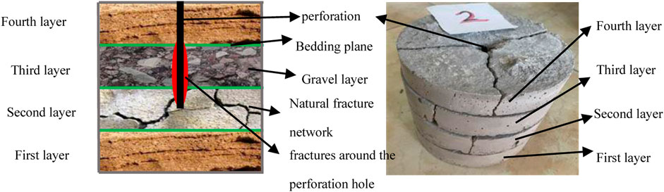
Figure 1. Schematic diagram of heterogeneous shale preparation.
2.2 Experimental parameters
Each rock sample features a perforation hole in its center, created using a 5 mm plastic pipe. The axis of the plastic pipe (perforation axis) is perpendicular to the layer plane. The perforation hole has a depth of 75 mm. If fractures occur around the perforation hole, a 1 mm paper sheet is used to simulate them, as demonstrated in Figure 2A. Once the rock sample is completed, the plastic pipe should be removed.
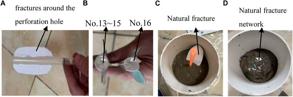
Figure 2. Preparation process of heterogeneous shale fracturing experiment.
Each rock sample undergoes lithological changes, including the presence of sandstone and gravel layers. The ratio of water, cement mortar, and cement sand in the sandstone layer is 0.5:1:4, and the grain size of sand ranges from 1 to 2 mm. The ratio of water, cement mortar, cement sand, and gravel in the gravel layer is 0.5:1:2.5:2.5, and the grain sizes of sand and gravel range from 1 to 2 mm and 6–10 mm, respectively.
Achieving natural fractures and natural fracture networks in each rock sample involves placing paper pieces. When simulating natural fractures, a large piece of paper is placed in the shale layer, with the paper surface forming an elliptical plane to avoid the influence of stress concentration at the geometric tip on fracture propagation, as demonstrated in Figure 2C. The thickness of the paper (corresponding to the thickness of the natural fracture) is 0.5 mm, and the angles between the natural fracture and the layer plane are 0°, 20°, and 45°. When simulating a natural fracture network, a large amount of small paper pieces is placed in the shale layer, as demonstrated in Figure 2D.
During the fracturing process, the fracturing fluid is made of clean water and a certain amount of silent breaking agent.
In this study, 14 sets of fracturing experiments were conducted, with the experimental rock samples numbered 1, 2, 5–16. No.1 rock sample serves as the control rock sample, with no bedding, no lithological changes, no fractures around the perforation hole, and no natural fractures (network). No.2 and 5–16 rock samples are all shale rock samples with layers. No.5 and No.6 rock samples feature a gravel layer: the No.5 gravel layer is located at the perforation hole’s tip section (the second layer), while the No.6 gravel layer is near the perforation root section (the third layer), and No.6 gravel layer is close to the perforation root section (the third layer). No.7 and No.8 rock samples feature a sandstone layer: the No.7 sandstone layer is at the perforation hole’s tip section (the second layer), and the No.8 sandstone layer is near the perforation root section (the third layer).
Natural fractures are presented in the second layer of No.9∼11, 13, 14, and 16 rock samples. The angles between the natural fractures and the layers of rock samples No.9 and 13 are 0°, while the angles between the natural fractures and the layers of rock samples No.10, 14, and 16 are 20°. The angle between the natural fractures and the layer of rock sample No.11 is 45°.
No.9∼11 rock samples do not have fractures around the perforation hole. No.13 and 14 rock samples have symmetrically developed fractures with a phase angle of 180° around the perforation hole. The difference between No.13 and 14 rock samples lies in the orientation of the horizontal projections of the fractures around the perforation holes: in No.13 rock sample, this projection is parallel to the horizontal projection of the long axis of the elliptical natural fracture, while in No.14 rock sample, it is parallel to the horizontal projection of the short axis of the elliptical natural fracture. In the No.16 rock sample, there are symmetrically developed fractures with a phase angle of 120° around the perforation hole, as shown in Figure 2B.
Natural fractures are presented in the second layer of No.12 and No.15 rock samples. The key difference between the two rock samples is that No.12 lacks fractures around the perforation hole, whereas No.15 has a symmetrical fracture around the perforation hole with a phase angle of 180°.
Fracturing the No.1, 2, and 5–16 rock samples to investigate the impact of shale layers on fracture propagation. Fracturing the No.5∼8 rock samples to study the influence of shale lithology changes on fracture propagation. Fracturing the No.9∼16 rock samples to investigate the effects of natural fractures/natural fracture networks and fractures around the perforation hole on fracture propagation.
The summarization of the grouping of experiments is shown in Table 1. It should be noted that the main purpose of this article is to explore the effects of various influencing factors, such as shale bedding, near-wellbore fractures, lithological changes, and the presence of fractures surrounding the perforation hole, on fracture propagation law and morphology, therefore the in situ stress has not been considered in the article. Also, because the rock sample is small, in order to make the fracturing process more stable, the fracturing injection rate is set to be 10 L/min.
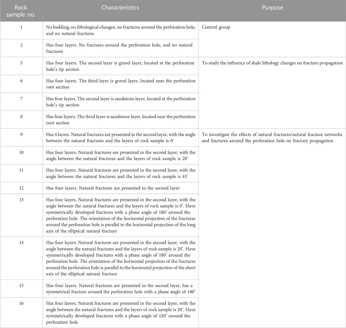
Table 1. Summarization of the grouping of experiments.
3 Results and analysis
3.1 Experimental results
Figures 2–16 show the fracture propagation diagram of No.1∼14 rock samples. In all the figures, black represents perforation, red represents fractures around the perforation, and blue represents natural fractures.
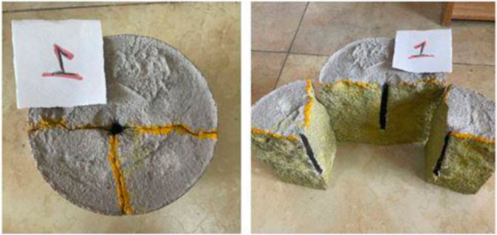
Figure 3. Fracture propagation diagram of No.1 shale rock sample.

Figure 4. Fracture propagation diagram of No.2 shale rock sample.
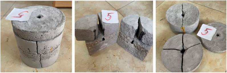
Figure 5. Fracture propagation diagram of No.5 shale rock sample.
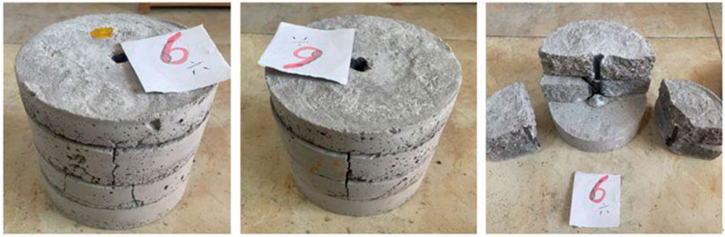
Figure 6. Fracture propagation diagram of No.6 shale rock sample.
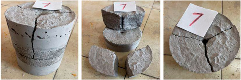
Figure 7. Fracture propagation diagram of No.7 shale rock sample.
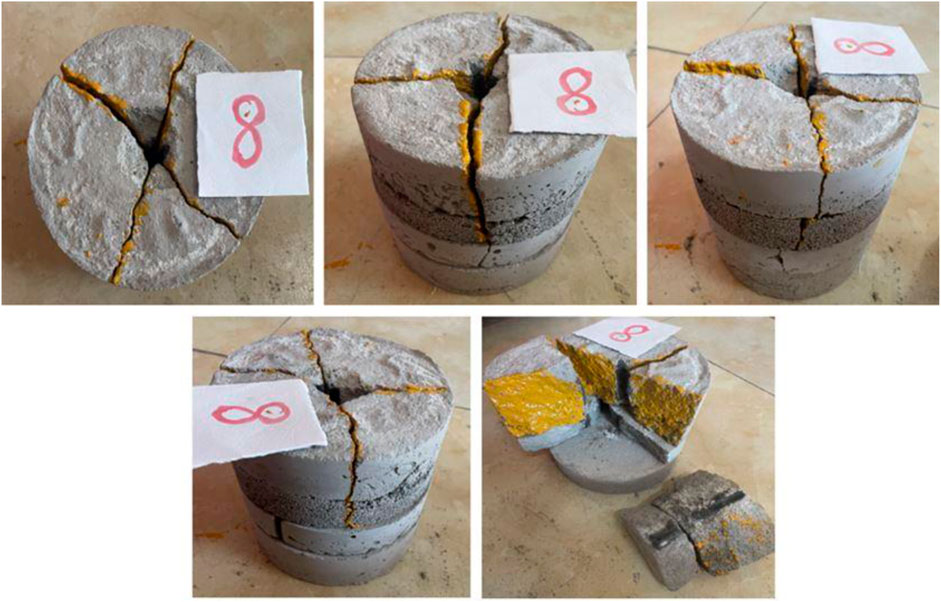
Figure 8. Fracture propagation diagram of No.8 shale rock sample.
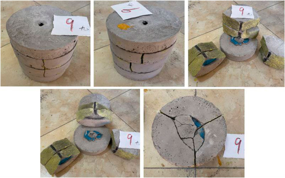
Figure 9. Fracture propagation diagram of No.9 shale rock sample.
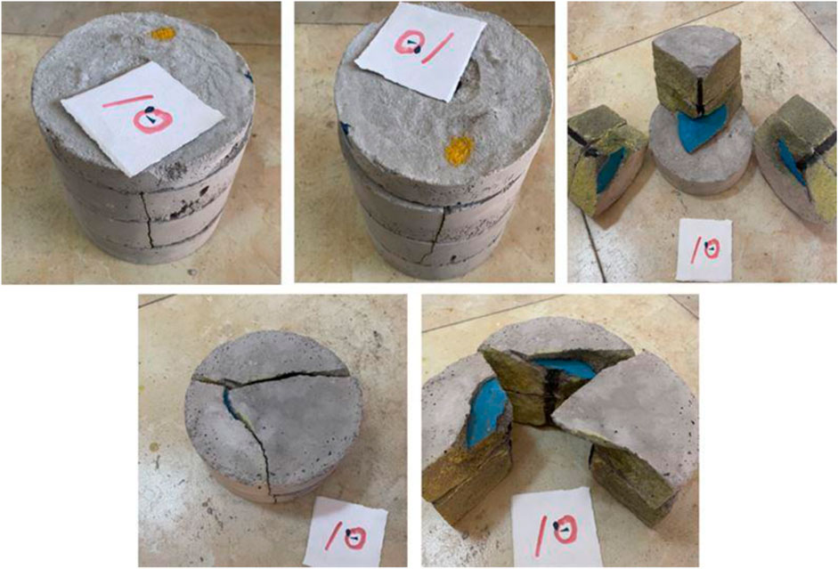
Figure 10. Fracture propagation diagram of No.10 shale rock sample.
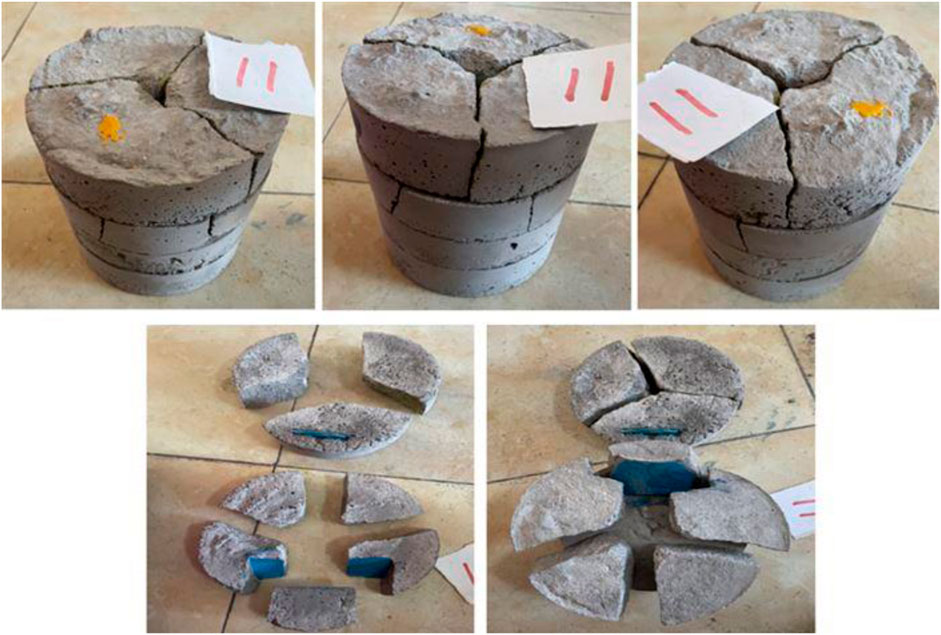
Figure 11. Fracture propagation diagram of No.11 shale rock sample.

Figure 12. Fracture propagation diagram of No.12 shale rock sample.
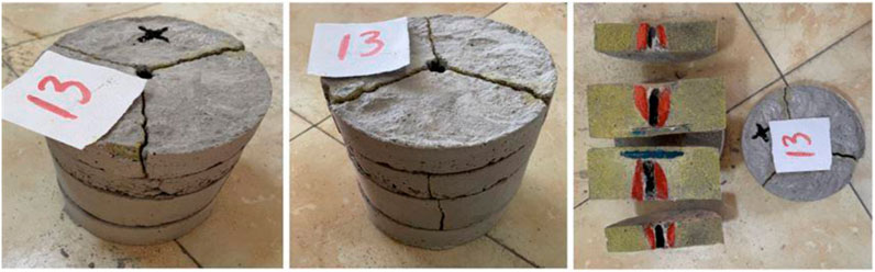
Figure 13. Fracture propagation diagram of No.13 shale rock sample.
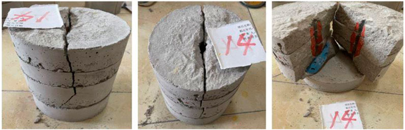
Figure 14. Fracture propagation diagram of No.14 shale rock sample.
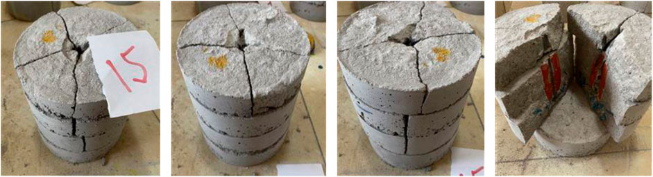
Figure 15. Fracture propagation diagram of No.15 shale rock sample.
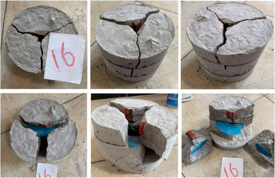
Figure 16. Fracture propagation diagram of No.16 shale rock sample.
3.2 Evaluation index of fracture complexity
Prior to analyzing the experimental results, two evaluation indicators must be introduced: the fracturing complexity index (FCI) and the stimulated reservoir volume (SRV). Ideally, we would like to observe a positive correlation between the fracturing volume and fracture complexity at each stage, where a larger fracturing volume (SRV) is preferable and more complex fracturing complexity index (FCI) is better.
However, in real-world fracturing operations, SRV and FCI are often contradictory, with most cases displaying negative correlation characteristics. In other words, fracturing fractures tend to expand mainly along the perforation axis, which is advantageous for SRV but not for FCI, or they mainly involve turning twists and intersections along the perforation axis, which is detrimental to SRV but beneficial to FCI.
Therefore, the following conclusions can be drawn from the analysis: if a certain influencing factor promotes the expansion of fracturing fractures along the perforation axis, it is positively correlated with SRV; if a certain influencing factor facilitates the orthogonal perforation axis expansion of the fracturing fracture, it is positively correlated with FCI.
3.3 Analysis of different influencing factors
1) The impact of delamination on fracture propagation
Rock sample No.1 serves as the control group. This rock sample lacks layer development, alterations in physical parameters, lithological changes, and the presence of natural fractures (nets), thus qualifying as an ideal homogeneous rock. During fracturing, it primarily forms a flat fracture surface parallel to the perforation axis and propagates forward in the direction of perforation advancement. It is challenging to create a twisted fracture surface that intersects the perforation axis at an angle. Thus, rock homogeneity has a positive correlation with SRV.
Rock sample No.2 and 5–16 all exhibit shale layer development. By examining the relationship between fracturing fractures and layer planes, we can observe the following: 1) During fracturing, shear dislocation typically occurs between shale layer planes, resulting in separation between different layer planes. 2) The number and distribution of perforation fractures formed during fracturing within a shale layer do not have a consistent correspondence with those in adjacent shale layers, particularly when the perforation channel remains intact and no peri-hole fractures are present, making this phenomenon more evident.
These two phenomena suggest that as the main shale fracture expands, the walls of each shale layer are continuously compressed. Due to differences in the pressure magnitude and direction on the walls between different shale layers, shear dislocation occurs, resulting in fractures that intersect the main fracture at an angle relative to the expansion direction of the main fracture. Clearly, this promotes an increase in fracture complexity. Concurrently, as the main shale fracture continuously traverses layer planes, it is influenced by the presence of layers, propagating forward in a stepped fashion, as illustrated in Figure 17. Comprehensive analysis indicates that shale layers have a positive correlation with FCI, which promotes the development of a hydraulic fracture network.
2) The impact of shale lithology change on hydraulic fracture propagation
A. The influence of gravel layer on fracture propagation
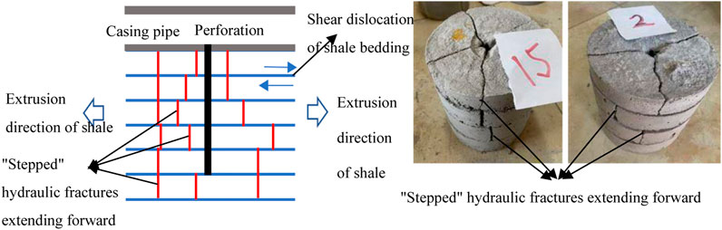
Figure 17. Diagram of step-shaped fracture.
No.5 and 6 rock samples are employed to investigate the impact of gravel layers on fracture propagation. In sample No.5, the gravel layer is located near the perforation tip, while in sample No.6, it is situated closer to the perforation root.
By examining fracture propagation, it is observed that fractures can effectively traverse and propagate forward regardless of whether the gravel layer is present at the perforation tip or near the perforation root, with the fracture surface remaining essentially flat and undistorted, as illustrated in Figure 18. This indicates that the gravel layer (4∼8 mm gravel) does not exhibit an inhibitory effect on the expansion of shale fractures along the wellbore axis, showing a positive correlation with SRV.
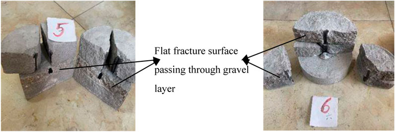
Figure 18. Diagram of hydraulic fracture propagation in gravel layer.
B. Influence of sandstone layer on fracture propagation
No.7 and No.8 rock samples are used to study the influence of sandstone layer existence on fracture propagation. The sandstone layer of No.7 rock sample appears near the perforation tip, and the sandstone layer of No.8 rock sample is closer to the perforation root.
From the fracture propagation of rock samples No.7 and No.8 in Figure 19., it can be observed that regardless of whether the sandstone layer is present at the perforation tip or near the perforation root, the fracture surface struggles to remain flat as the fractures pass through, resulting in significant distortion. Specifically, for rock sample No.7, the propagation mode of fractures shifts from the interlayer propagation of shale to the intralayer propagation of sandstone, leading to a significant increase in the complexity of fractures, as illustrated in Figure 19.
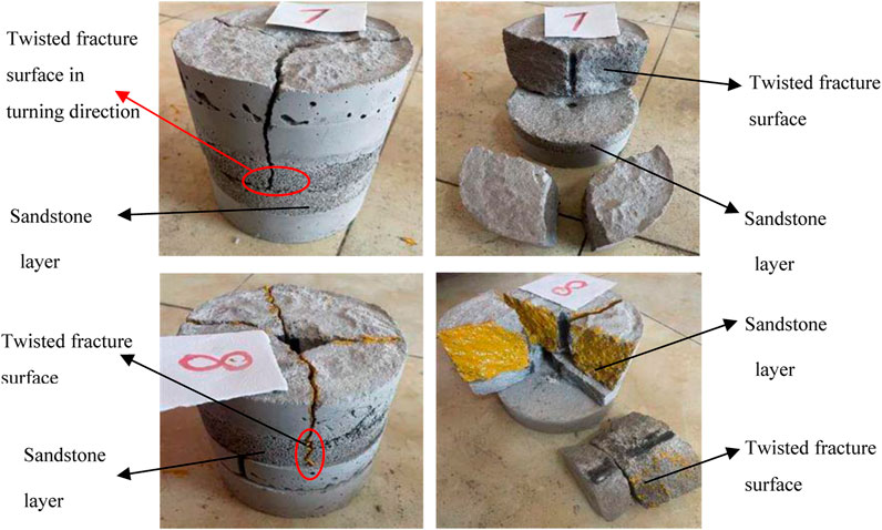
Figure 19. Diagram of hydraulic fracture propagation in sandstone layer.
Consequently, the sandstone layer demonstrates a pronounced inhibitory effect on the forward expansion of shale fractures along the perforation axis and exhibits a strong positive correlation with FCI.
3) Influence of shale natural fractures on fracture propagation
A. Influence of natural fractures on fracture propagation
No.9∼11, 13, 14, and No.16 rock samples were selected to investigate the impact of natural fractures on fracture propagation. The natural fractures in samples No.9 and 13 are parallel to the layer plane and perpendicular to the perforation axis. The angles between the natural fractures of samples No. 10, 14, and 16 and the layer plane approximate 20°, while the angle between the natural fractures of sample No.11 and the layer plane is approximately 45°. Samples No.9, 10, and 11 lack micro fractures around the perforation hole, whereas micro fractures parallel to the perforation axis are prefabricated around the perforation hole in samples No.13, 14, and 16.
It can be seen from the fracture propagation of the six rock samples No.9∼11, 13, 14 and 16 that for a single perforation, when the scale of natural fractures is large and as the angle between the natural fracture surface and the layer plane varies from 0° to 20°–45°, regardless of whether there are micro fractures parallel to the perforation axis around the perforation hole, the fractures struggle to directly pass through the natural fractures, primarily bypassing them instead. In this process, the fractures are distorted to a certain extent, leading to an increase in complexity, as shown in Figure 20 Note: A large scale of natural fractures significantly impedes the forward expansion of fractures and exhibits a strong positive correlation with FCI.
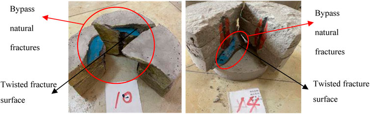
Figure 20. Diagram of hydraulic fracture propagation encounter natural fracture.
B. Influence of natural fractures network on fracture propagation
No.12 and 15 rock samples were selected to investigate the impact of natural fractures networks on fracture propagation. Sample No.12 lacks micro fractures around the perforation hole, whereas micro fractures parallel to the perforation axis are prefabricated around the perforation hole in sample No.15.
It can be seen from the fracture propagation of No.12 and No.15 rock samples that, for a single perforation, regardless of whether there are micro fractures parallel to the perforation axis around the perforation, the fractures can pass through the natural fractures network. Although the fracture surface is distorted to some extent and the complexity of the fractures increases, there is no detour phenomenon. Note: In this experiment, the natural fractures network exhibits a certain blocking effect on the forward expansion of the fractures, which is smaller than that of the natural fractures, and its positive correlation with FCI is weaker than that of the natural fractures.
4) Influence of fracture around the perforation hole on fracture propagation
Through comparative analysis of the fracture propagation of samples No.9 and 13, 10 and 14, it can be seen that when there are micro fractures parallel to the perforation axis around the perforation hole (No.13 and 14 rock samples), the generation and propagation of fracturing fractures are significantly affected by micro fractures, and the coincidence of the two fracture surfaces is quite high, as shown in Figure 21A. At the same time, when the fracturing fractures expand forward and encounter natural fractures, the distortion is also significantly reduced, and the step-like expansion of the interlayer fracture surface is obviously weakened, as shown in Figure 21B. Through analysis of sample No.16, it is further verified that microfractures around the perforation hole have significant control over the generation and expansion of fracturing fractures, and partially inhibit the detour phenomenon when fracturing fractures encounter natural fractures, as shown in Figure 21C. All the above demonstrates that when there are micro fractures around the perforation hole parallel to the perforation axis, it will help to enhance the ability of the main fractures to pass through the natural fractures, which is positively related to SRV.
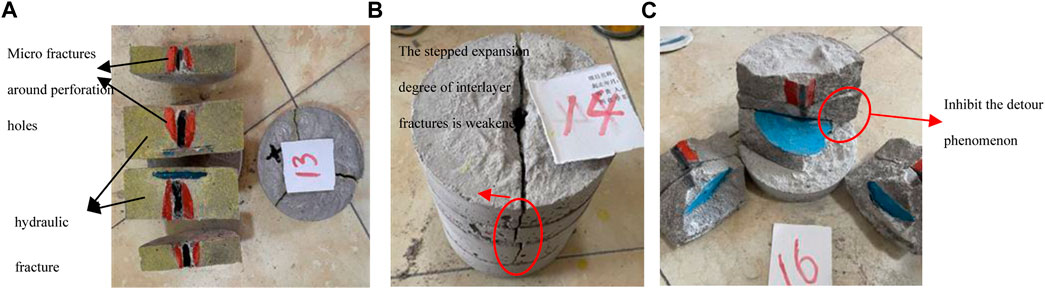
Figure 21. Effect of fractures around the perforation hole on the hydraulic fracture propagation (encounter natural fracture).
A comparative analysis of the fracture expansion of samples No.12 and 15 (Figure 22) reveals that when micro fractures parallel to the perforation axis surround the perforation hole, when the fracturing fractures expand forward and encounter the natural fractures network, the distortion of the fracture surface is significantly reduced, and the stepped expansion of the interlayer fracture surface is also significantly reduced. This indicates that the presence of micro fractures around the perforation hole parallel to the perforation axis enhances the ability of the main fractures to pass through the natural fractures network, and is positively correlated with SRV.
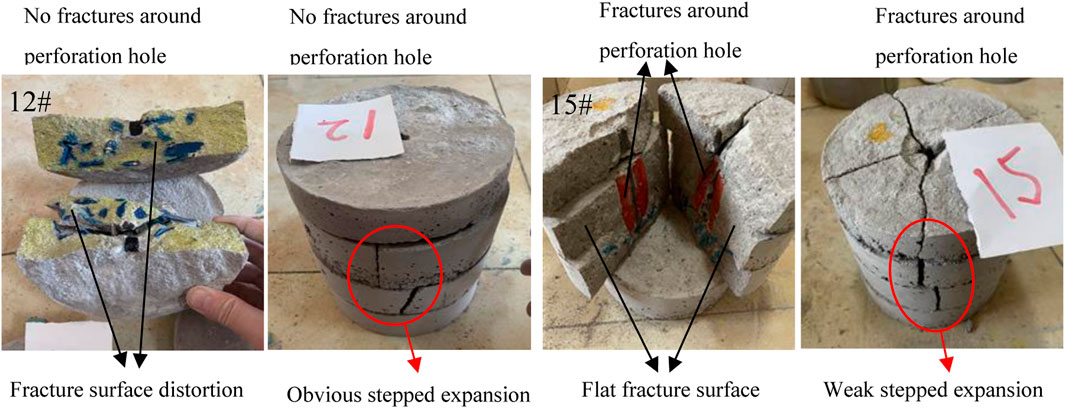
Figure 22. Effect of fractures around the perforation hole on the hydraulic fracture propagation (encounter natural fracture network).
4 Conclusion
1) In shale fracturing, shear dislocation typically occurs between layers, resulting in separation between distinct layer planes. The main fracture primarily propagates through layers in a stepped configuration.
2) The presence of sandstone in heterogeneous shale significantly impedes fracturing fractures, causing severe distortion and deflection.
3) When the scale of natural fractures is large, it induces twisting and directional changes in the fracturing fracture. The natural fractures network also contributes to the distortion of fracturing fractures, albeit to a lesser extent than large-scale natural fractures.
4) The presence of micro fractures parallel to the perforation axis around the perforation hole augments the ability of the main fracturing fractures to traverse the natural fractures.
Data availability statement
The original contributions presented in the study are included in the article/supplementary material, further inquiries can be directed to the corresponding author.
Author contributions
WB: Conceptualization, Data curation, Formal Analysis, Funding acquisition, Methodology, Project administration, Resources, Visualization, Writing–original draft, Writing–review and editing. JT: Conceptualization, Data curation, Formal Analysis, Project administration, Supervision, Writing–original draft, Writing–review and editing. XB: Conceptualization, Formal Analysis, Writing–original draft. NK:Data curation, Formal analysis, Resources, Writing–original draft. TP: Writing–original draft, Writing–review and editing. ZY: Formal analysis, Writing–original draft.
Funding
The authors declare financial support was received for the research, authorship, and/or publication of this article. This study was supported by Research on development and deformation mechanism of high temperature resistant soft metal materials (No. 2021DQ03-01), and Research on the technology of reaming while drilling and open hole clad with expandable tubelar (No. 2021DJ4102), and Research on the new specification of expandable tubelar used for the wellbore reconstruction in unconventional oil and gas reservoirs (No. CPETCY202304), and Research on key technologies and equipment for drilling and completion of ten thousand meters of ultra-deep oil and gas resources (No. 2022ZG06).
Conflict of interest
Authors WB, JT, XB, NK, TP, and ZY were employed by CNPC Engineering Technology R&D Company Limited.
Publisher’s note
All claims expressed in this article are solely those of the authors and do not necessarily represent those of their affiliated organizations, or those of the publisher, the editors and the reviewers. Any product that may be evaluated in this article, or claim that may be made by its manufacturer, is not guaranteed or endorsed by the publisher.
References
Bunger, A. P., Jeffrey, R. G., Kear, J., Zhang, H., and Morgan, M. (2011). “Experimental investigation of the interaction among closely spaced hydraulic fractures,” in Proceedings of the 45th US Rock Mechanics/Geomechanics Symposium, San Francisco, California, June 2011. ARMA-11-318.
Chuprakov, D. A., and Prioul, R. (2015). “Hydraulic fracture height containment by weak horizontal interfaces,” in Proceedings of the SPE hydraulic fracturing technology conference, The Woodlands, Texas, USA, February 2015 (Society of Petroleum Engineers).
Dontsov, E. V. (2022). Analysis of a constant height hydraulic fracture driven by a power-law fluid. Rock Mech. Bull. 1 (1), 100003. doi:10.1016/j.rockmb.2022.100003
Dontsov, E. V., and Peirce, A. P. (2015). An enhanced pseudo-3D model for hydraulic fracturing accounting for viscous height growth, non-local elasticity, and lateral toughness. Eng. Fract. Mech. 142, 116–139. doi:10.1016/j.engfracmech.2015.05.043
Ge, J., and Ghassemi, A. (2008). “Analysis of failure potential around a hydraulic fracture in jointed rock,” in Proceedings of the 42nd US Rock Mechanics Symposium (USRMS), San Francisco, California, June 2008 (American Rock Mechanics Association).
Huang, L. K., He, R., Yang, Z. Z., Tan, P., Chen, W., Li, X., et al. (2023a). Exploring hydraulic fracture behavior in glutenite formation with strong heterogeneity and variable lithology based on DEM simulation. Eng. Fract. Mech. 278, 109020. doi:10.1016/j.engfracmech.2022.109020
Huang, L. K., Liu, J. J., Zhang, F. S., Dontsov, E., and Damjanac, B. (2019). Exploring the influence of rock inherent heterogeneity and grain size on hydraulic fracturing using discrete element modeling. Int. J. Solids Struct. 176, 207–220. doi:10.1016/j.ijsolstr.2019.06.018
Huang, L. K., Tan, J., Fu, H. F., Liu, J., Chen, X., Liao, X., et al. (2023b). The non-plane initiation and propagation mechanism of multiple hydraulic fractures in tight reservoirs considering stress shadow effects. Eng. Fract. Mech. 292, 109570. doi:10.1016/j.engfracmech.2023.109570
Liu, S., and Valkó, P. P. (2015). “An improved equilibrium-height model for predicting hydraulic fracture height migration in multi-layered formations,” in Proceedings of the SPE Hydraulic Fracturing Technology Conference, The Woodlands, Texas, USA, February 2015 (Society of Petroleum Engineers).
Ma, X., Zhang, S., Zhang, X., Liu, J., Jin, J., Cheng, W., et al. (2022). Lithology-controlled stress variations of Longmaxi shale–Example of an appraisal wellbore in the Changning area. Rock Mech. Bull. 1 (1), 100002. doi:10.1016/j.rockmb.2022.100002
Nie, Y. X., Zhang, G. Q., Wen, J., Li, S. Y., and Zhou, D. W. (2021). Cyclic injection to reduce hydraulic fracture surface roughness in glutenite reservoirs. Int. J. Rock Mech. Min. Sci. 142, 104740. doi:10.1016/j.ijrmms.2021.104740
Shaffer, R. J., Thorpe, R. K., Ingraffea, A. R., and Heuze, F. E. (1984). “Numerical and physical studies of fluid driven fracture propagation in jointed rock, paper SPE 12881,” in Proceedings of the 1984 Unconventional Gas Recovery Symposium, Pittsburgh, PA, USA, May 1984, 471–482.
Shi, X., Qin, Y., Gao, Q., Liu, S., Xu, H. X., and Yu, T. X. (2023). Experimental study on hydraulic fracture propagation in heterogeneous glutenite rock. Geoenergy Sci. Eng. 225, 211673. doi:10.1016/j.geoen.2023.211673
Tan, P., Fu, S. H., Chen, Z. W., and Zhao, Q. (2023). Experimental investigation on fracture growth for integrated hydraulic fracturing in multiple gas bearing formations. Geoenergy Sci. Eng. 231, 212316. doi:10.1016/j.geoen.2023.212316
Tan, P., Jin, Y., and Pang, H. W. (2021). Hydraulic fracture vertical propagation behavior in transversely isotropic layered shale formation with transition zone using XFEM-based CZM method. Eng. Fract. Mech. 248, 107707. doi:10.1016/j.engfracmech.2021.107707
Tan, P., Pang, H. W., Zhang, R. X., Jin, Y., Zhou, Y., Kao, J., et al. (2020). Experimental investigation into hydraulic fracture geometry and proppant migration characteristics for southeastern Sichuan deep shale reservoirs. J. Petroleum Sci. Eng. 184, 106517. doi:10.1016/j.petrol.2019.106517
Wang, J. J., and Clifton, R. J. (1991). “Fracture growth in the presence of highly stressed layers,” in Proceedings of the SPE Western Regional Meeting, Long Beach, California, March 1991 (Society of Petroleum Engineers).
Warpinski, N. R., Schmidt, R. A., and Northrop, D. A. (1982). In-situ stresses: the predominant influence on hydraulic fracture containment. J. Petroleum Technol. 34 (03), 653–664. doi:10.2118/8932-pa
Xiao, H. T., Yue, Z. Q., Tham, G. L., and Chen, Y. (2005). Stress intensity factors for penny-shaped cracks perpendicular to graded interfacial zone of bonded bi-materials. Eng. Fract. Mech. 72, 121–143. doi:10.1016/j.engfracmech.2004.03.005
Keywords: heterogeneous shale, fracturing experiment, hydraulic fracturing, propagation law, propagation morphology
Citation: Bin W, Tao J, Binggui X, Kun N, Peng T and Yi Z (2024) Experimental study on hydraulic fracture propagation behavior in heterogeneous shale formations. Front. Energy Res. 11:1309591. doi: 10.3389/fenrg.2023.1309591
Received: 08 October 2023; Accepted: 10 November 2023;
Published: 03 September 2024.
Edited by:
Yan Peng, China University of Petroleum, Beijing, ChinaCopyright © 2024 Bin, Tao, Binggui, Kun, Peng and Yi. This is an open-access article distributed under the terms of the Creative Commons Attribution License (CC BY). The use, distribution or reproduction in other forums is permitted, provided the original author(s) and the copyright owner(s) are credited and that the original publication in this journal is cited, in accordance with accepted academic practice. No use, distribution or reproduction is permitted which does not comply with these terms.
*Correspondence: Tan Peng, dGFucGVuZzA5anlAMTYzLmNvbQ==