 Xiaosong Wang
 Dazhi Wang1*
- 1School of Information Science and Engineering, Northeastern University, Shenyang, China
- 2State Grid Shandong Electric Power Company, Yantai, China
- 3China North Vehicle Research Institute, Beijing, China
This paper presents a control method of dual active full bridge (DAB) DC/DC converter based on neural network Sliding mode control under the reduced order modeling method, which is used to enhance the output voltage regulation and improve the system robustness. Sliding mode control (SMC) is famous for its robustness and improving the dynamic performance of nonlinear systems. However, it includes drawbacks such as complex modeling, chattering, and decreased tracking performance. Therefore, through the method of reduced order modeling, the Radial Basis Function neural network algorithm is selected to modify and design the traditional sliding mode variable structure controller, completing the design of neural network approximation terms and adaptive laws. The proposed reduced order modeling and RBF(Radial Basis Function Neural Network)-SMC scheme simplifies the dual active full bridge modeling process, completes the parameter approximation of the sliding mode controller, and eliminates the chattering problem. Firstly, through simulation and comparative analysis of commonly used modeling methods for dual active full bridge, a reduced order modeling method was adopted to simplify the design process. Then, by ingeniously designing the sliding mode surface and Radial Basis Function control law, and using neural network to modify the Sliding mode control technology, the chattering problem, load disturbance and voltage fluctuation influence of the sliding mode controller are improved. The stability of the control method is proved by Lyapunov stability theory. Finally, the proposed RBF-SMC method is compared with PI linear control and classical Sliding mode control methods through simulation and experiments to verify the effectiveness of the proposed control method.
1 Introduction
1.1 Motivation and challenges
With the development of distributed power systems such as new energy generation and electric vehicles, dual active full bridge (DAB) converters have been widely used in various high-power applications as a practical topology due to their advantages such as complete electrical isolation, high power density, high voltage conversion ratio, and easy implementation of soft switching (Zhao et al., 2014; Liu et al., 2019). However, the power transmission of distributed power sources has the characteristics of intermittency, randomness, and instability, which puts forward stricter requirements for the output performance of DAB converters (De Doncker et al., 1991).
In the above applications, modeling and designing controllers with specific steady-state and dynamic performance for DAB converters is crucial, various topology variants, modeling and control schemes, and their applications of DAB converters have been proposed in references (Xiao et al., 2020; Ma et al., 2021; Shao et al., 2022a).
1.2 Motivation and challenges
Compared with traditional DC/DC converters, DAB modeling is more challenging because one of its state variables, the inductance current, is pure AC (Zhang et al., 2017; Khatua et al., 2022). proposed a generalized average model and a discrete time model, respectively. The former takes into account the inductance current and the model is a high-order model. The latter can achieve good control and accuracy, but the modeling complexity is high (Li et al., 2019; Shao et al., 2022b). reduces the modeling process to first order by ignoring the inductance current, and has been experimentally verified to have good accuracy, which is of great significance to the selection of modeling methods in this paper. Considering the complexity and accuracy of modeling, this article compares and analyzes the commonly used modeling methods for DAB through simulation. Based on the simulation results, it is decided to use a reduced order model for modeling (Kaiwart et al., 2023).
For the design of DAB controller, the early work mainly focused on the design of DAB small-signal modeling to design its (linear) controller, such as PI linear control (Krismer and Kolar, 2009; Segaran et al., 2013). When large disturbances occur, linear control may experience errors. The solution is to introduce a feedback system to improve robustness (An et al., 2018; Zhao et al., 2021). Research shows that introducing nonlinearity in control can improve performance, but there is a lack of nonlinear stage management and design methods for the system. Therefore, current attention is focused on the design of DAB nonlinear controllers.
The sliding mode variable structure controller has superior adaptive ability, and can quickly complete convergence when in sliding mode state, making it very suitable for the design of time-delay uncertain systems (Martmez-Salamero et al., 1998; Tan et al., 2011). However, throughout the whole working process of Sliding mode control, it can be seen as a switching control signal with a certain degree of uncertainty and high frequency, so there will be chattering problems in the whole control process, and it can be seen that such chattering phenomenon mostly occurs near the sliding mode surface. A SMC scheme based on the average output current model of DAB converters was proposed in (Carrizosa et al., 2013; Talbi et al., 2015), which does not include integral control, resulting in significant current overshoot and steady-state error. In addition, no experimental verification was provided for the designed controller. Apply single integral SMC to a simple DC/DC boost converter (Tan et al., 2007; Marcos-Pastor et al., 2015). According to (Tan et al., 2012), even if single integral SMC (SISMC) is applied to boost or buck converters, there may still be steady-state errors (Lin et al., 2011; Tan et al., 2012; Chincholkar and Chan, 2017). proposed the Double Integral SMC (DISMC) (Tiwary et al., 2020; Tiwary et al., 2023), Proposed the Super Torsional Sliding Mode Method (ST-SMC) (Russo et al., 2021), The control of dual active bridge (DAB) is realized by using the generalized super twist algorithm. Within the innovative framework of the electric aircraft (MEA) concept, the battery pack can be charged under standard load conditions, and the battery can be used to supply power for additional loads under overload conditions. The above improvement methods all require setting controller parameters based on experience, which can easily lead to inaccurate parameters.
Neural networks, as a highly nonlinear system, have a long history of development. As an advanced control algorithm, their powerful knowledge extraction ability, superior learning ability, and strong robustness in the field of control have all led to their increasing application in modern research. Reference (Maruta and Hoshino, 2019; Liu, 2021) proposes the use of neural networks to control the converter. In reference (Kurokawa et al., 2010), the author identified a control object implemented using a DC/DC converter as the algorithm, delved into neural network algorithms, and proposed a neural network predictive controller to improve the dynamic output response of the converter. The output response results showed that the designed neural network predictive controller often exhibits overcompensation due to its large variation in compensation effect, it will affect the overall control effect. Reference (Maruta et al., 2014) proposed the use of neural network algorithms for parameter prediction by exploring the control principles of time series and continuous neural networks, and then established a simulation testing platform for the system.
1.3 Motivation and challenges
For the design of reduced order model DAB controller, there are few literature on RBF based SMC, because it is difficult to construct a state equation to design the control law. Whether it is a typical Sliding mode control or a higher-order Sliding mode control, it is necessary to consider setting controller parameters, which means that when the DAB is controlled, the parameters need to be constantly changed to make the control effect better. In this paper, RBF neural network is used to transform the SMC, complete the parameter approximation of the sliding mode controller, avoiding the trial and error process of controller parameters, and improve the chattering problem, load disturbance and voltage fluctuation effect of the sliding mode controller, And compare with PI linear control and classical SMC methods to verify the effectiveness of the proposed control method.
2 DAB converter modeling
2.1 Operating principle
The DAB system structure is shown in Figure 1. The DAB topology has symmetry, with both ends being DC ports, consisting of 2 symmetrical H-bridges (
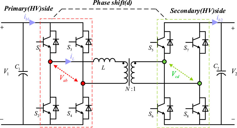
FIGURE 1. DAB system architecture.
The driving pulse waveform, primary and secondary bridge voltage waveform, and transformer current waveform of the DAB converter modulated by single-phase offset (SPS) are shown in Figure 2. Among them,
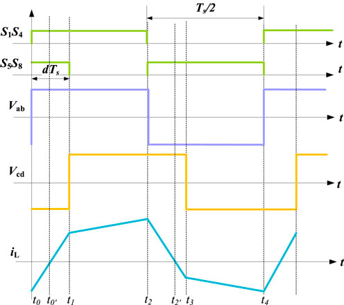
FIGURE 2. The waveform of the driving pulse and bridge voltage of the switch tube (primary bridge voltage
The SPS modulation principle of DAB is as follows. Assuming that the converter is in operation and stable state, according to the forward power flow control principle shown in Figure 2, the working mode of DAB can be divided into six states, as shown in Figure 3.
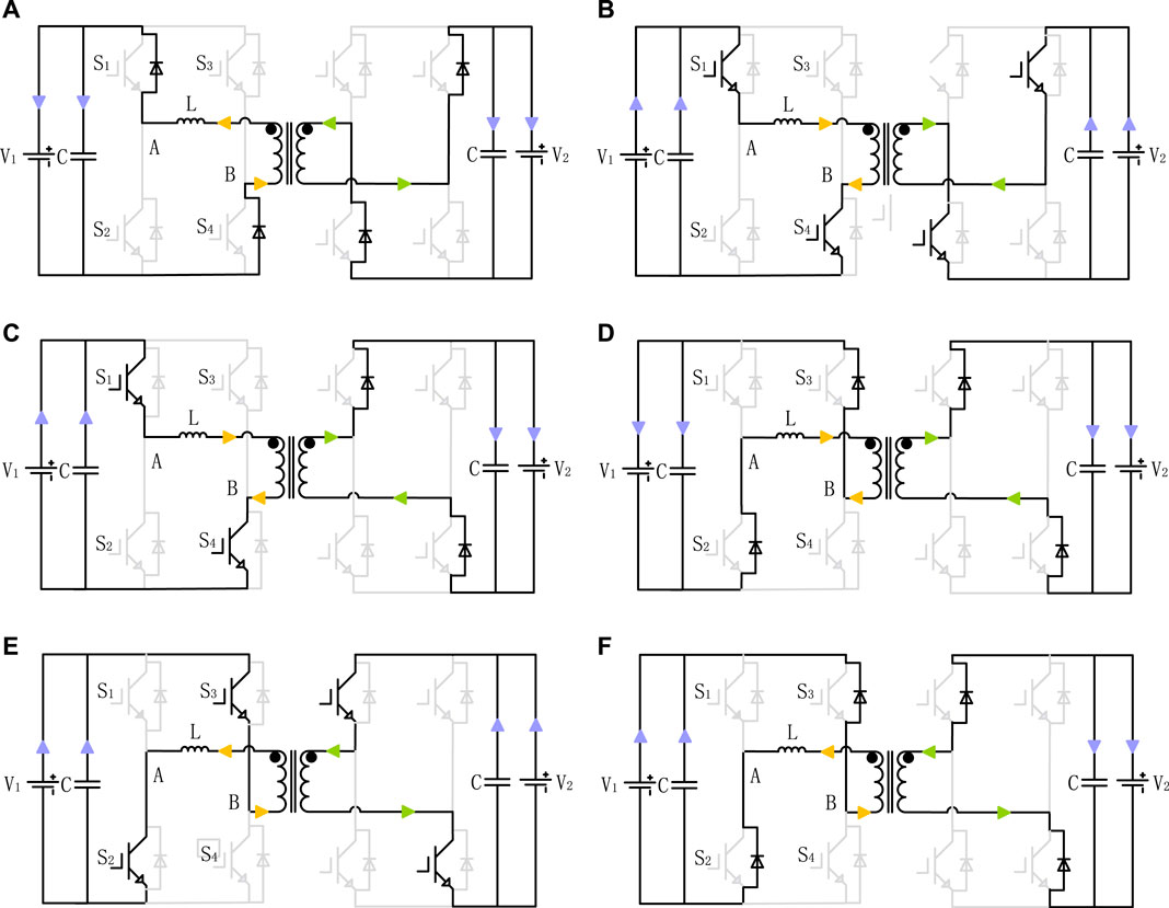
FIGURE 3. Typical operating modes of DAB during forward power flow of SPS.
Mode 1:
Mode 2:
Mode 3:
Mode 3:
Mode 4:
Mode 5:
Mode 6:
DAB converters can effectively transmit power at both ends by changing the shift ratio
Where
2.2 Reduced order model
This article adopts the modeling method of reduced order model, which ignores inductance
Where
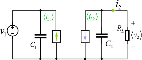
FIGURE 4. DAB reduced order model.
As
By introducing the disturbance at the phase shift ratio,
Where
According to Figure 4 and Eq. 8, the control block diagram from
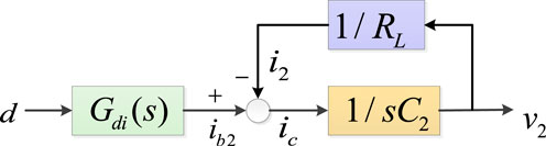
FIGURE 5. Block diagram of reduced order model.
Based on the above analysis, it can be known that the reduced order model of DAB is a first-order system. The effectiveness will be verified through simulation in the following text.
2.3 Simulation comparison of different DAB modeling methods
In order to verify the accuracy of the reduced order model, transfer functions for four modeling methods were established and simulation results were provided. The simulation parameters are shown in Table 1, where the resistance
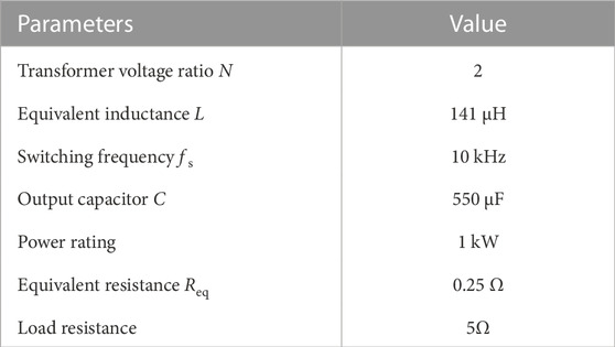
TABLE 1. DAB parameters for simulation comparison.
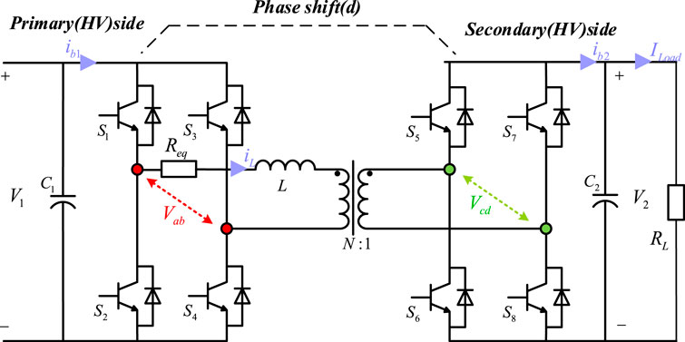
FIGURE 6. DAB circuit for model comparison.
Figure 7 shows the comparison of simulation results in a large signal model, where the shift ratio d steps from 0.05 to 0.1 at t = 0.1s and the input voltage
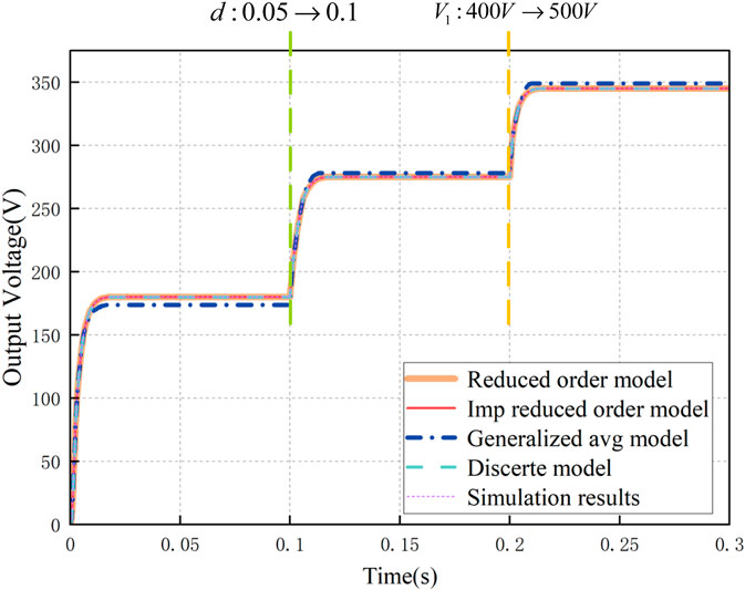
FIGURE 7. Comparison of large-signal models.
Figure 8 shows the bode diagram of the small-signal modeling
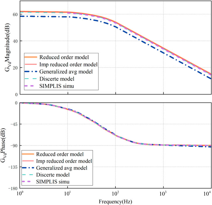
FIGURE 8. Comparison of the bode plot of small-signal models (from
In fact, the generalized average model is based on Fourier series. Since the inductance current is AC current, it contains many items. When k = 1 is considered, its modeling becomes a third-order model, and when the load resistance is considered, it becomes a sixth order model, so the modeling is very complex. The discrete time model, on the other hand, assumes that the state variables only change at different time points. As shown in Figure 9, a cycle is divided into four states and the state equations for each state are obtained. Therefore, the modeling process of the discrete time model is also very complex.
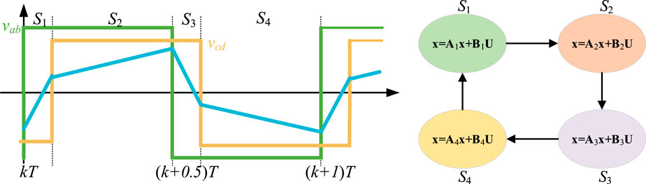
FIGURE 9. Discrete-time modeling for a DAB: (A) States definition; (B) State-space equation in each state.
Through simulation experiments, it can be seen that the error of the reduced order model, improved reduced order model, and discrete time model for large and small signals is basically 0, while the error of the generalized average model for large signals is about 3.35%, and the error of small signals is about 6.7%, due to its neglect of higher-order components.
The comparison of the modeling methods provided in the literature is shown in Table 2.
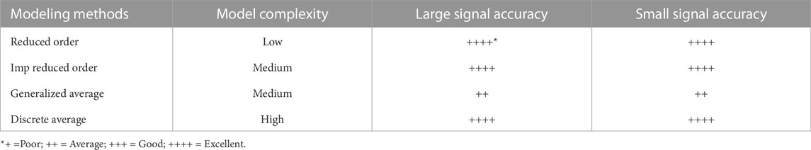
TABLE 2. Comparison of DAB modeling methods.
From the table, it can be seen that although the improved reduced order model and discrete time model perform well in terms of modeling accuracy, their modeling is relatively complex. The generalized average model has poor accuracy due to its neglect of high-order components of current. The reduced order model performs excellently in terms of modeling complexity and accuracy, so it is chosen as the reference model.
3 Traditional SMC design of DAB
According to Figure 4 and Eq. 8, the state equation of DAB can be obtained
Eq. 12 can be expressed as an equation in the following form When
Where
Take system error as
Where
Where the gain
Therefore, this error is dynamically represented as
Where
Write the equation of state in the following form
For the convenience of formula derivation, modify Equation 20 as follows
Where
In addition, the time derivative of the sliding surface is
Due to the zero derivative of the reference voltage, substituting equation (13) into (24) yields
Let
Perform stability analysis on the system and select the Lyapunov function as
Therefore, the proposed switching control should ensure the following
In order to verify the conditions in (28) using the designed control law, substituting (26) can obtain
Due to
From Eq. 26, it can be seen that in the designed controller expression, there is a sign function
For the SMC designed above, for the Robust control with large disturbance, for example, changes in input voltage, load, and shift ratio, the control effect is enhanced, and the chattering will increase significantly. This disadvantage will be reflected in subsequent simulations.
4 RBF-SMC for DAB
Due to the chattering phenomenon of sliding mode variable structure controller, RBF neural network algorithm is selected to optimize the design of sliding mode controller and complete the parameter approximation of sliding mode controller.
As a type of feedforward network, the system architecture of RBF network is mainly divided into three layers: first, the input layer, which mainly includes the signal source nodes of the system and is the first layer of neural network; The second is the hidden layer, also known as the middle layer, which includes the number of units required according to the control performance. The transformation function of the hidden layer is mirror symmetry, and the subtraction of gradual attenuation relative to the center point is a nonlinear radial function; The third layer is the output layer, which plays a joint role in responding to the input layer and the hidden layer. It should be noted that the conversion from the input layer to the middle layer is nonlinear, while the conversion from the middle layer to the output layer is linear, as shown in Figure 10.
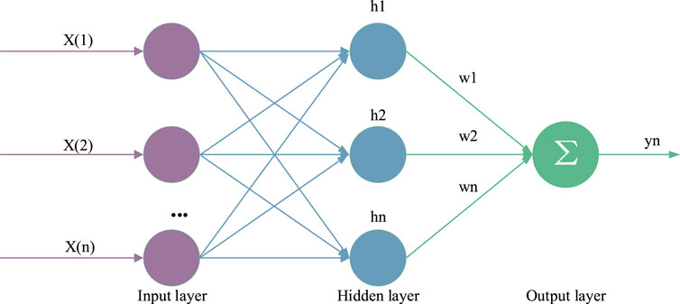
FIGURE 10. The topological structure of RBF networks.
The network algorithm is
Where
Network input is
The network output is
The output approximation term is
Where
Simultaneously ordering
Substituting it into (26) can obtain
Same as Eq. 31, the saturation function
Continuing to design the adaptive law of the controller, substituting (37) into (25) yields
Which
Where
Equation 38 can be expressed as
Select Lyapunov function.
Where
Taking the derivative of Eq. 41 and substituting (40) into it yields
Taken from the law of adaptation as
Substituting equation (43) into (42) yields
Take
It can be seen that the role of the robust term
The overall block diagram of the RBF-SMC controller designed in this article is shown in Figure 11. Firstly, the controller module trains data to generate a control signal
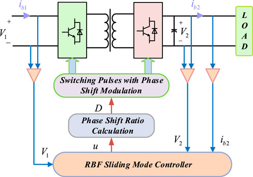
FIGURE 11. Overall Block Diagram of DAB for RBF-SMC.
5 Comparative research in simulation
This article establishes a simulation model of a DAB converter using Matlab/Simulink tools, and provides simulation results of voltage response, load disturbance, and voltage disturbance when the DAB converter adopts PI, SMC, and RBF-SMC methods. The parameters of the converter component and the controller gain are given in Tables 3, 4, respectively.
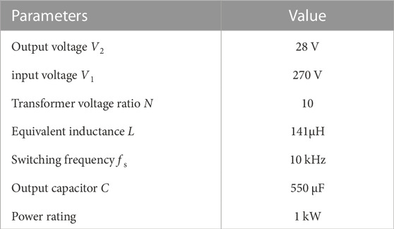
TABLE 3. Converter parameters.
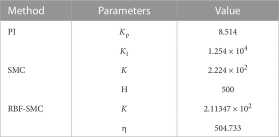
TABLE 4. Converter parameters.
5.1 RBF neural network training
Using Matlab’s radial basis function neural network toolbox, obtain the center and width of the RBF network hidden layer basis functions, respectively. In the neural network Sliding mode control system, the RBF neural network learning process is shown in Figure 12. In the RBF neural network sliding mode controller, The unknown interference input of the system is
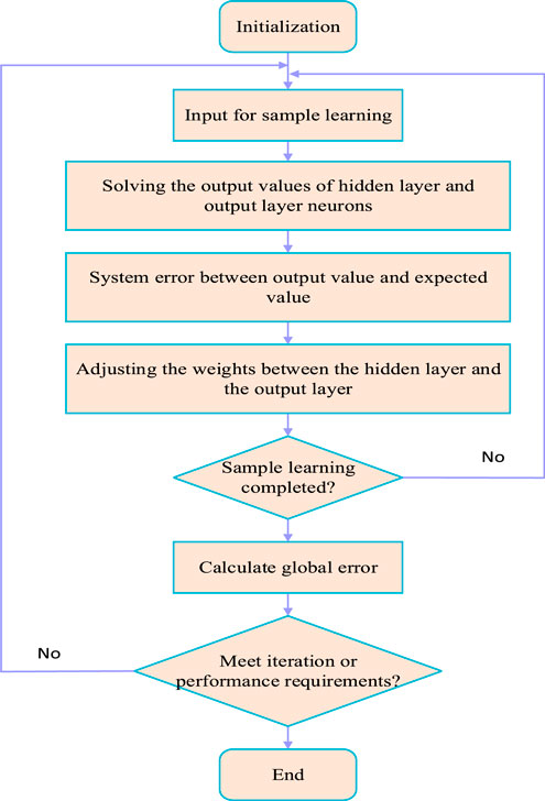
FIGURE 12. RBF neural network learning process.
In the iterative requirements of the final training end, the whole training process of the RBF neural network sliding mode controller will end immediately once the global error is less than the minimum value set in advance. On the contrary, it means that the RBF neural network still has not completed all training and continues to return to the learning steps of the input samples until the iterative requirements are met.
5.2 Simulation results
5.2.1 Voltage response simulation
Firstly, conduct RBF neural network training, and use Matlab’s radial basis function neural network toolbox to obtain the center and width of RBF network hidden layer basis functions. The expected output voltage is 28V, and the voltage response simulations of the three control methods are shown in Figure 13.
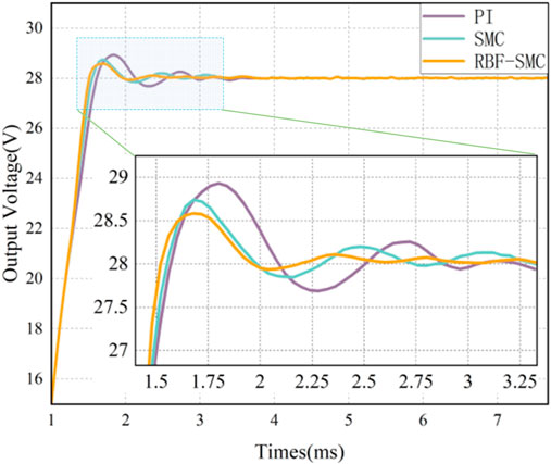
FIGURE 13. Waveform of voltage response simulation experiment.
It can be seen from Table 5 that in the startup response phase, compared with the converter based on traditional PI control, the voltage response time of the system has significantly decreased after adopting Sliding mode control, and the overshoot of the system has also significantly decreased. However, it can be seen from the voltage response simulation waveforms under these three control modes that the chattering of the converter under Sliding mode control is larger than that under PI control. After the RBF neural network algorithm is used to design, the output voltage of the DAB circuit can track the set expected voltage in a short time, and the chattering phenomenon is suppressed. The comparison results are shown in Table 5.
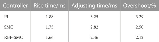
TABLE 5. Comparison of voltage response simulation experimental data.
5.2.2 Load disturbance simulation
At 4.75 m, an electronic load meter (120V/120A) with a power level of 1 kW was used to alternately switch the load between 8A and 33A. The voltage response is shown in Figure 14. The experimental data comparison results of the system load disturbance simulation test under these three control conditions are shown in Table 6.

FIGURE 14. Comparison of voltage control performances for load variation: (A) Load decrease (33A–8A); (B) Load increase (8A–33A).
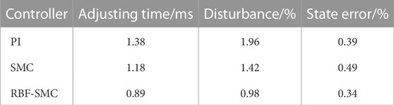
TABLE 6. Comparison of load disturbance simulation experimental data.
It can be seen from Table 6 that the DAB converter controlled by sliding mode variable structure can achieve rapid response when the load is changed and the two controls respond to disturbance, and its voltage adjustment effect is better than that of PI control. However, from the experimental data, it can also be seen that the steady-state error of traditional sliding mode variable structure control is larger because of the chattering phenomenon of Sliding mode control, but after being modified by the RBF neural network algorithm, the time from interference generation to stability recovery has been improved.
5.2.3 Voltage disturbance simulation
Figure 15 shows the output waveform of the voltage response comparison curves of the three controllers when there is disturbance in the input voltage (switching between 200V and 330V). The comparison results of simulation experimental data after system voltage disturbance under three types of control are shown in Table 7.
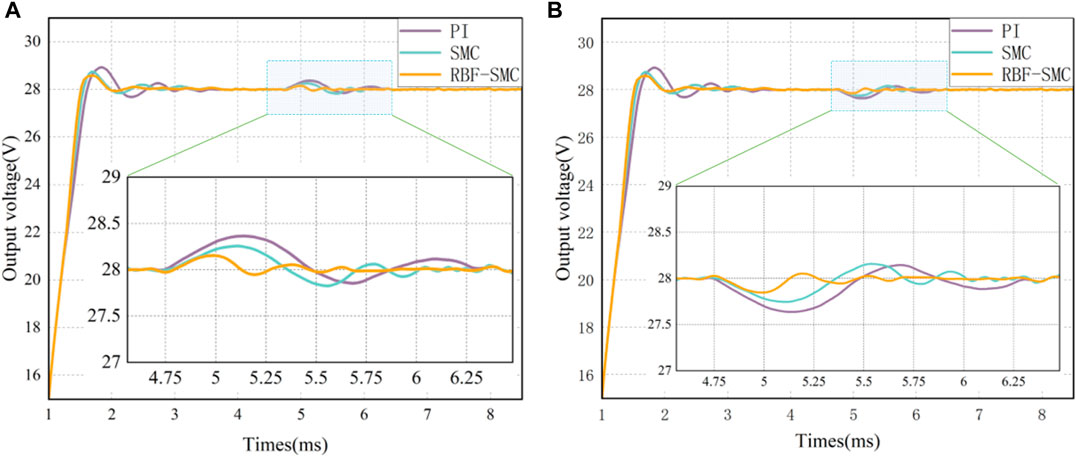
FIGURE 15. Comparison of voltage control performances for input voltage variation: (A) Input voltage increase (200V–330V); (B) Input voltage decrease (330V–200V).
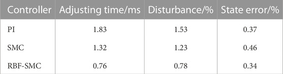
TABLE 7. Comparison of voltage disturbance simulation experimental data.
It can be seen from Figure 15 and Table 7 that when the input voltage changes, compared with the traditional PI controlled converter, the Sliding mode control converter has a better ability to resist voltage fluctuations. However, from the comparison data of simulation experiments, it can be seen that the same situation exists when the load is disturbed, and the steady-state error of the converter under Sliding mode control increases due to chattering. After the modification of the RBF network, the chattering of the system’s output response has been suppressed to a certain extent and the steady-state error of the system has decreased. At the same time, due to the strong robustness of RBF-SMC, external voltage fluctuations will not have a significant negative impact on the converter system.
6 Experimental results and discussion
The peripheral hardware circuit of the controller using analog control technology is relatively complex, and it is also troublesome to complete high-precision control. At the same time, it is easily affected by the external environment and has poor applicability. Practical experimental verification and flexibility in daily applications are insufficient. The digital controlled switching power supply has the ability to monitor the operating status of the converter in real-time and handle system faults instantaneously, which can meet the control requirements of the switching converter. On the other hand, due to the high integration of the microprocessor, the peripheral hardware circuit will not increase with the complexity of the controller. Therefore, this article uses the STM32 control chip to optimize the design of the control algorithm and conduct subsequent comparative experiments. The two H-bridges use semi independent IGBT modules with built-in driver circuits, and the simulator is used to download the written program to the STM32 microcontroller. The DC load cabinet and DC input power supply conduct system load disturbance and voltage disturbance experiments by changing their load and input voltage. The data generated by the system can be sent to the upper computer through the serial port, and the experimental data under the three control strategies in the upper computer can be collected, Use Matlab to process the three types of experimental data and display them on the same graph, making it easier to observe and compare the measured results. The prototype and experimental environment designed in this article are shown in Figure 16.
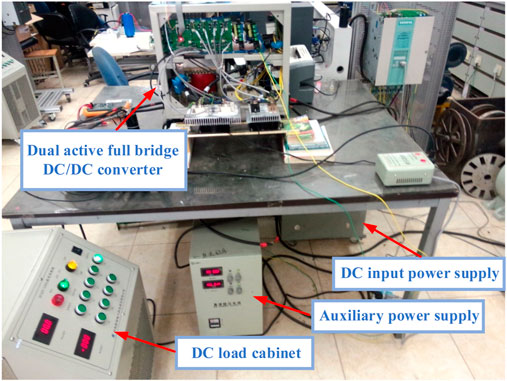
FIGURE 16. DAB converter prototype and test environment.
The table provides the system parameters of the hardware implemented DAB converter. By adjusting the data parameters of the converter under the three control strategies of PI, SMC, and RBF-SMC, the experimental comparison was completed. The measured curves as shown in Figures 17–19 was obtained, showing the voltage response, load disturbance response, and voltage disturbance output response waveforms of the DAB converter under three control schemes.
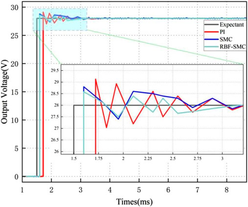
FIGURE 17. Voltage response.
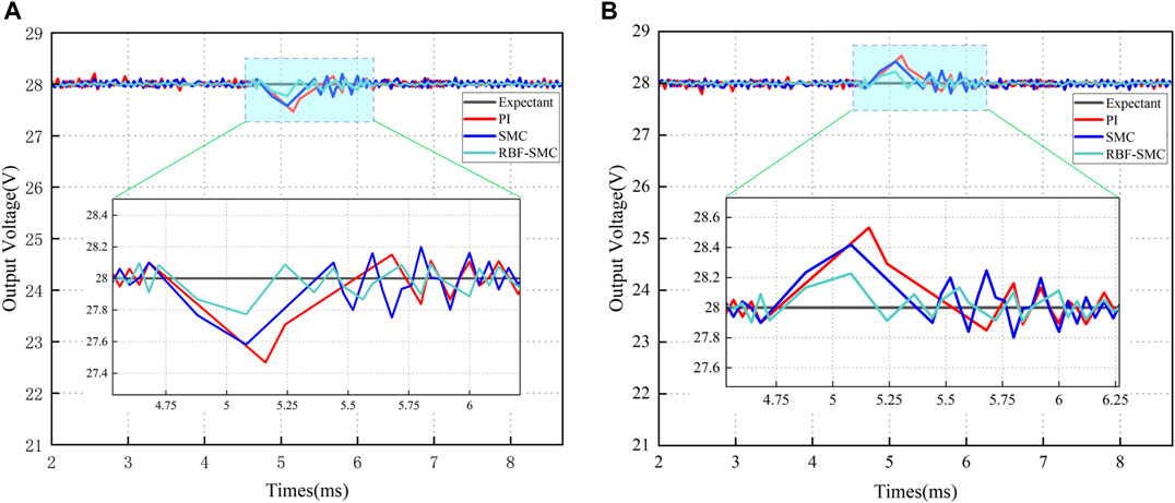
FIGURE 18. Load disturbance: (A) Load decrease (33A–8A); (B) Load increase (8A–33A).
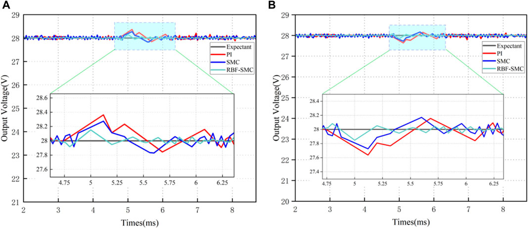
FIGURE 19. Voltage disturbance: (A) Input voltage increase (200V–330V); (B) Input voltage decrease (330V–200V).
From the above experimental results, it can be seen that the measured experimental conclusions are generally consistent with the simulation results. The response speed of RBF-SMC during the startup response phase is the fastest, with an adjustment time increase of approximately 0.83 m and 0.55 m compared to PI and SMC, respectively, and an overshoot of only 2.12%; In the stage of load disturbance, the adjustment time from slow to fast is PI control, SMC, and RBF-SMC, and the adjustment time of RBF-SMC is increased by about 0.62 ms compared to PI control; In the voltage disturbance stage, RBF-SMC still performs better and generates the smallest voltage disturbance. This series of data confirms that under the same experimental platform, the control performance of the designed RBF-SMC is better than that of PI and SMC.
7 Conclusion
This paper proposes a control method of dual active full bridge DC/DC converter based on neural network Sliding mode control under the reduced order modeling method, which improves the chattering problem, load disturbance and voltage fluctuation influence of sliding mode controller, and improves the robustness of output voltage. By comparing and analyzing different modeling methods of DAB through simulation, it was verified that the reduced order modeling method performs well in terms of modeling complexity and accuracy, making the design of the controller simpler than other methods. Buffering phenomenon may occur during typical SMC control processes, and the proposed RBF-SMC scheme is used to eliminate this ripple by approximating the parameters of the sliding mode controller. For possible large disturbances, such as sudden changes in input voltage or load, robust control is obtained. The performance of the proposed control method was verified through simulation and compared with traditional voltage control based on traditional SMC and PI. After comparing the three control methods through simulation, it was verified that the proposed method has higher robustness. In addition, an experimental platform has been established to verify the effectiveness of the proposed method through experimental results, during normal operation of the system, the response time and adjustment time of the output voltage have been improved, and when the system is subjected to large disturbances, the adjustment time, disturbance amount, and overshoot of the output voltage have been significantly improved compared to the first two methods. The DAB control method proposed in this article has some help for future electric vehicle energy storage devices, renewable energy systems, and power system microgrids.
Data availability statement
The original contributions presented in the study are included in the article/Supplementary Material, further inquiries can be directed to the corresponding author.
Author contributions
XW and DW contributed to conception and design of the study. GS organized the database. YN, KS, and YL performed the statistical analysis. XW wrote the first draft of the manuscript. XW and DW wrote sections of the manuscript. All authors contributed to the article and approved the submitted version.
Funding
This research is supported by the Natural Science Foundation of China under Grant 52077027.
Acknowledgments
The authors thank the chief editor and the reviewers for their valuable comments on how to improve the manuscript.
Conflict of interest
Authors GS was employed by State Grid Shandong Electric Power Company.
The remaining authors declare that the research was conducted in the absence of any commercial or financial relationships that could be construed as a potential conflict of interest.
Publisher’s note
All claims expressed in this article are solely those of the authors and do not necessarily represent those of their affiliated organizations, or those of the publisher, the editors and the reviewers. Any product that may be evaluated in this article, or claim that may be made by its manufacturer, is not guaranteed or endorsed by the publisher.
References
An, F., Song, W., ang, K. Y., Hou, N., and Ma, J. (2018). Improved dynamic performance of dual active bridge dc–dc converters using MPC scheme. IET Power Electron 11 (11), 1756–1765. doi:10.1049/iet-pel.2017.0707
Carrizosa, M. J., Benchaib, A., Alou, P ., and Damm, G. “DC transformer for DC/DC connection in HVDC network,” in Proceedings of the 15th Eur Conf IEEE Power Electron Appl., Lille, France, September 2013, 1–10.
Chincholkar, S. H., and Chan, C.-Y . (2017). Design of fixed-frequency pulsewidth-modulation-based sliding-mode controllers for the quadratic boost converter. IEEE Trans. Circuits Syst. II, Exp. Briefs 64 (1), 51–55. doi:10.1109/tcsii.2016.2546902
De Doncker, R. W. A. A., Divan, D. M., and Kheraluwala, M. H. (1991). A three-phase soft-switched high-power-density DC/DC converter for high-power applications. IEEE Trans. Ind. Appl. 27 (1), 63–73. doi:10.1109/28.67533
Kaiwart, V. K., Jamatia, A., Chakrabarti, A., Das, B., Kasari, P. R., and Laskar, N. “Modeling of dual active bridge with extended phase shift and dual phase shift modulation technique using reduced order model method,” in Proceedings of the 2023 Second International Conference on Electronics and Renewable Systems (ICEARS), Tuticorin, India, March 2023, 13–20.
Khatua, S., Kastha, D., and Kapat, S. “Exact-order discrete-time modeling of a DAB derived hybrid switched-capacitor converter,” in Proceedings of the 2022 IEEE Applied Power Electronics Conference and Exposition (APEC), Houston, TX, USA, March 2022, 2051–2057.
Krismer, F., and Kolar, J. W. (2009). Accurate small-signal model for the digital control of an automotive bidirectional dual active bridge. IEEE Trans. Power Electron. 24 (12), 2756–2768. doi:10.1109/tpel.2009.2027904
Kurokawa, F., Maruta, H., and Mizoguchi, T. “A new digital control DC-DC converter with multi-layer neural network predictor,” in Proceedings of the International Conference on Machine Learning and Applications, Miami, FL, USA, December 2010, 638–643.
Li, K., Yang, Y., Tan, S. -C., and Hui, R. S. -Y. “Sliding-mode-based direct power control of dual-active-bridge DC-DC converters,” in Proceedings of the 2019 IEEE Applied Power Electronics Conference and Exposition (APEC), Anaheim, CA, USA, March 2019, 188–192.
Lin, F.-J., Chen, S.-Y ., and Huang, M.-S. (2011). Intelligent double integral sliding-mode control for five-degree-of-freedom active magnetic bearing system. IET Contr . Theory Appl. 5 (11), 1287–1303. doi:10.1049/iet-cta.2010.0237
Liu, J. “A backpropagation neural network controller trained using PID for digitally-controlled DC-DC switching converters,” in Proceedings of the 2021 IEEE 16th Conference on Industrial Electronics and Applications (ICIEA), Chengdu, China, August 2021, 946–951.
Liu, T., Yang, X., Chen, W., Li, Y., Xuan, Y., Huang, L., et al. (2019). Design and implementation of high efficiency control schemeof dual active bridge based 10 kV/1 MW solid state transformer for PVapplication. IEEE Trans. Power Electron. 34 (5), 4223–4238. doi:10.1109/tpel.2018.2864657
Ma, Y., Wen, H., Zhou, X., and Yin, J. “Modeling and control strategy simulation of dual active bridge DC-DC converter,” in Proceedings of the 2021 IEEE International Conference on Mechatronics and Automation (ICMA), Takamatsu, Japan, August 2021, 431–435.
Marcos-Pastor, A., Vidal-Idiarte, E., Cid-Pastor, A., and Martínez-Salamero, L. (2015). Loss-free resistor-based power factor correction using a semi-bridgeless boost rectifier in sliding-mode control. IEEE Trans. Power Electron. 30 (10), 5842–5853. doi:10.1109/tpel.2014.2369431
Martmez-Salamero, L., Calvente, J., Giral, R., Poveda, A., and Fossas, E. (1998). Analysis of a bidirectional coupled-inductor cuk converter operating in sliding mode. IEEE Trans. Circuits Syst. I Fundam. Theory Appl. 45 (4), 355–363. doi:10.1109/81.669058
Maruta, H., Motomura, M., and Kurokawa, F. “Characteristics study of neural network aided digital control for DC-DC converter,” in Proceedings of the Power Electronics Conference, Hiroshima, Japan, May 2014, 3611–3615.
Maruta, H., and Hoshino, D. “Transient response improvement of repetitive-trained neural network controlled DC-DC converter with overcompensation suppression,” in Proceedings of the IECON 2019 - 45th Annual Conference of the IEEE Industrial Electronics Society, Lisbon, Portugal, October 2019, 2088–2093.
Russo, A., Canciello, G., and Cavallo, A. “Generalized super-twisting control of a dual active bridge for more electric aircraft,” in Proceedings of the 2021 European Control Conference (ECC), Delft, Netherlands, June 2021, 1610–1615.
Segaran, D., Holmes, D. G., and McGrath, B. P. (2013). Enhanced load step response for a bidirectional DC–DC converter. IEEE Trans. Power Electron. 28 (1), 371–379. doi:10.1109/tpel.2012.2200505
Shao, S., Chen, L., Shan, Z., Gao, F., Chen, H., Sha, D., et al. (2022a). Modeling and advanced control of dual-active-bridge DC–DC converters: A review. IEEE Trans. Power Electron. 37 (2), 1524–1547. doi:10.1109/tpel.2021.3108157
Shao, S., Chen, L., Shan, Z., Gao, F., Chen, H., Sha, D., et al. (2022b). Modeling and advanced control of dual-active-bridge DC–DC converters: A review. IEEE Trans. Power Electron. 37 (2), 1524–1547. doi:10.1109/tpel.2021.3108157
Talbi, S., Mabwe, A. M., and Hajjaji, A. E. “Control of a bidirectional dual active bridge converter for charge and discharge of a Li-ion battery,” in Proceedings of the. 41st Annu. Conf. IEEE Ind. Electron. Soc., Yokohama, Japan, November 2015, 849–856.
Tan, S.-C., Lai, Y . M., Tse, C. K., Mart´ınez-Salamero, L., and Wu, C.-K. (2007). A fast-response sliding-mode controller for boost-type converters with a wide range of operating conditions. IEEE Trans. Ind. Electron. 54 (6), 3276–3286. doi:10.1109/tie.2007.905969
Tan, S. C., Lai, Y . M., and Tse, C. K. (2011). Sliding mode control of switching power converters: Techniques and implementation. Boca Raton, Florida, United States: CRC Press.
Tan, S. C., Lai, Y . M., and Tse, C. K. (2012). Sliding mode control of switching power converters—techniques and implementation. Boca Raton, FL, USA: CRC Press.
Tiwary, N., Naik N, V., Panda, A. K., Narendra, A., and Lenka, R. K. (2023). A robust voltage control of DAB converter with super-twisting sliding mode approach. IEEE J. Emerg. Sel. Top. Industrial Electron. 4 (1), 288–298. doi:10.1109/jestie.2022.3227007
Tiwary, N., Panda, A. K., Lenka, R. K., and Narendra, A. “Super twisting sliding mode control of dual active bridge DC-DC converter,” in Proceedings of the 2020 IEEE International Conference on Power Electronics, Drives and Energy Systems (PEDES), Jaipur, India, December 2020, 1–5.
Xiao, Z., Lei, W., Gao, G., Cui, Y., Kang, Q., and Wang, M. “Transient current constraint of DAB converter based on model predictive control,” in Proceedings of the 2020 IEEE 9th International Power Electronics and Motion Control Conference (IPEMC2020-ECCE Asia), Nanjing, China, November 2020, 203–207.
Zhang, K., Shan, Z., and Jatskevich, J. (2017). Large- and small-signal average-value modeling of dual-active-bridge DC–DC converter considering power losses. IEEE Trans. Power Electron. 32 (3), 1964–1974. doi:10.1109/tpel.2016.2555929
Zhao, B., Song, Q., Liu, W., and Sun, Y. (2014). Overview of dual-active-bridge isolated bidirectional DC–DC converter for high-frequency-link power-conversion system. IEEE Trans. Power Electron. 29 (8), 4091–4106. doi:10.1109/tpel.2013.2289913
Keywords: dual active full bridge converter, reduced order mode, sliding mode variable structure control, RBF neural network, dynamic response
Citation: Wang X, Wang D, Sun G, Ni Y, Song K and Li Y (2023) A robust voltage control of dual active full bridge converter based on RBF neural network sliding mode control with reduced order modeling approach. Front. Energy Res. 11:1225269. doi: 10.3389/fenrg.2023.1225269
Received: 19 May 2023; Accepted: 30 June 2023;
Published: 27 July 2023.
Edited by:
Wenliang Zhao, Shandong University, ChinaReviewed by:
Christian Rojas, Federico Santa María Technical University, ChileJiaming Hu, Shenyang University of Technology, China
Copyright © 2023 Wang, Wang, Sun, Ni, Song and Li. This is an open-access article distributed under the terms of the Creative Commons Attribution License (CC BY). The use, distribution or reproduction in other forums is permitted, provided the original author(s) and the copyright owner(s) are credited and that the original publication in this journal is cited, in accordance with accepted academic practice. No use, distribution or reproduction is permitted which does not comply with these terms.
*Correspondence: Dazhi Wang, cHJvZHp3QDEyNi5jb20=