
95% of researchers rate our articles as excellent or good
Learn more about the work of our research integrity team to safeguard the quality of each article we publish.
Find out more
ORIGINAL RESEARCH article
Front. Energy Res. , 25 January 2023
Sec. Nuclear Energy
Volume 10 - 2022 | https://doi.org/10.3389/fenrg.2022.988745
This article is part of the Research Topic Experimental and Numerical Studies on Liquid Metal Cooled Fast Reactors View all 17 articles
 Yuwen Xu1
 Di Yun1,2*
 Xu Yan1Ping Zhang1Wei Yan3,4Yanfen Li3,4Chao Li5Jiao Li5Tongmin Zhang6Jun Li6
 Junjun Zhou6Long Kang6Chenyang Lu1
Oxide Dispersion Strengthened (ODS) steels with nano-scale oxides have become one of the candidate materials used in advanced nuclear reactor systems. A novel MX-ODS steel with extremely low carbon content was irradiated with 3 MeV Fe ions at 550°C up to peak damage of 70 dpa. The steel contains uniformly distributed Y2O3 nano-precipitates with an average size of 3.5 nm and a number density of 5 × 10²²/m3. A V-rich shell was found surrounding the core of Y, O, and Si at some particles. Two types of large precipitates, Y-Ta-Si oxides, and VN, were observed in the steel instead of carbides. Voids of very small size are present due to irradiation and the calculated void swelling was only 0.004%, suggesting good irradiation tolerance of the MX-ODS steel in this study. Fine and dense oxide nano-precipitates and their shell-core structure remained stable while the shape of large precipitates changed after irradiation.
Advanced nuclear reactor systems with higher safety, reliability, and thermal efficiency are being developed as sustainable and clean energy sources. In the fourth generation fission reactors and fusion reactors, structure materials have to sustain harsh environments such as high temperatures and neutron irradiation of especially high doses, and this sets a limit for the development of advanced nuclear reactors. Nanostructured oxide dispersion strengthened (ODS) steels have become one of the promising candidate materials because of their outstanding high-temperature properties and remarkable tolerance to irradiation-induced swelling (Ukai et al., 2017; Odette, 2018). The oxide nano-precipitates should be of small size, high number density, uniform distribution, and should retain good stability in high temperature and irradiation environment. They could pin dislocations and grain boundaries, and could serve as defect sinks to achieve good swelling resistance (Lin et al., 2021).
A series of ODS steels has been developed and tested to be used as the fusion blanket structural material (Zinkle et al., 2017) or in liquid lead-bismuth eutectic (LBE) or lead cooled reactors (Kimura et al., 2011; Song et al., 2019). M23C6 carbides, which commonly appear in ferritic/martensitic ODS steels and pin the grain boundaries, would be unstable in the high-temperature environment (Zheng et al., 2020), setting a limitation on the working temperature for such ODS steels. A novel MX-ODS steel with extremely low carbon content was developed (RUI, 2022) to eliminate M23C6 carbides and take the advantage of MX (M = Ta/V, X = C/N) precipitates as second-phase strengthening (Tan et al., 2016).
Both MX and M23C6 phases suffered from instability issues during irradiation, which may affect void swelling and mechanical properties. Several studies have been carried out to examine their stability under irradiation. Kano et al. (2018a) suggested that the size of both MX and M23C6 phase decreased slightly after ion irradiation of 50 dpa (damage per atom). The reduction of the MX phase was less severe than M23C6 in neutron irradiation according to Tan et al. (2020), while Tanigawa et al. (2007) reported that TaC disappeared when M23C6 reduced in size and became amorphous after ion irradiation. Furthermore, the MX phase of different elements responded differently to irradiation. TaN dissolved under ion irradiation while TaC and VN tended to further precipitate as reported by Tan et al. (2014), depending both on their chemical compositions and shapes. The excess vacancies created by irradiation can affect the stability of the MX phase, and the properties of the second phase may determine the behavior of point defects in return. Thus, based on these previous results, it is determined that in order to predict the response and the effect of the MX phase in the MX-ODS steel during irradiation, more investigations still need to be carried out in a systematic way.
In this work, a heavy ion irradiation experiment was conducted on an MX-ODS steel with 3 MeV Fe ions at 550°C to peak damage of 70 dpa. Ion irradiation with a high damage rate, no sample activation, and economical efficiency, has been widely used as a screening tool for alloy development (WAS, 2017). Fe ions were chosen to exclude the effects of injected atoms of other types. The steel is envisaged to be used in the lead-cooled fast reactor as fuel cladding with an outlet temperature of 550°C, which is slightly higher than the peak swelling temperature in ferritic/martensitic steel at about 420°C–470°C according to Toloczko et al. (2014). However, the peak swelling temperature may shift due to the differences of melting temperature of different steels. Considering a relatively good resistance to swelling commonly expected for ODS steels, a peak damage of 70 dpa was reached in the experiment. Such choice of ion irradiation dose serves two purposes: 1) To clarify the swelling resistance of the MX-ODS steel, and 2) To investigate the stability of MX phases under ion irradiation to an intermediate dose level.
In this work, the fine oxides of Y2O3 and large precipitates of metallic oxides and VN were characterized in the as-received materials first. Attention was paid to oxide nano-precipitates, which contribute to the resistance of irradiation effects. Then after irradiation, voids distribution and void swelling were particularly concerned. The response of oxide nano-precipitates to irradiation was examined as well.
The MX-ODS steel used in this study was produced by powder metallurgy. The pre-alloy powder smaller than 150 μm produced by gas atomization was mixed with 0.30 wt% Y2O3 power with the particle size of 100–200 nm. Mechanical alloying (MA) of the powder was conducted with grinding rotate peed of 150 r/min for 90 h under the protection of high purity Ar gas (99.99%). Then the powder was vacuum degassing and consolidated by hot forging. Finally, heat treatment was conducted at 980°C for 1 h and 750°C for 1 h. A detailed fabrication process can be found elsewhere (Rui et al., 2022). The chemical compositions are shown in Table 1. Carbon content was controlled to an extremely low level to eliminate carbides in the steel. The addition of N was expected to form the MX phase (M = Ta, V, X = N) to strengthen the steel. A tempered martensitic structure can be seen and the average grain size is 0.93 μm, as shown in Figure 1.

TABLE 1. Chemical composition of the MX-ODS steel (wt%).

FIGURE 1. A tempered martensitic structure of the as-received sample with fine grains in TEM.
Non-irradiated specimens for TEM characterization were prepared by jet electropolishing. Samples were mechanically ground with SiC paper to less than 100 μm of thickness and punched into 3 mm discs. A solution of 10% perchloric acid in ethanol was used as an electrolyte and electropolishing was conducted at −20°C with a potential of 19 V. A focused ion beam (FIB) lift-out specimen with a thickness of 80 nm was fabricated to examine the cross-section after irradiation. Another FIB lift-out specimen was prepared in the same irradiation sample, but in the area which was covered by part of the holder during irradiation. Thus the specimen did not receive irradiation but went through the same condition (a high temperature of 550°C) during irradiation.
Microstructures of samples before and after irradiation were characterized by field emission transmission electron microscopy (TEM) using JEOL-F200 and Talos-F200X. Under-focus and over-focus of both 1000 nm in bright-field TEM were used to manifest voids. High angle annular dark field (HADDF) STEM and energy-dispersive X-ray spectroscopy (EDS) were performed for distinguishing and conducting the chemical analysis of nanoparticles and precipitates in the samples.
The steel received was a rod with a radius of 7.5 mm. The samples for the irradiation experiment were prepared by wire-cut electric spark to a thickness of about 3 mm. The surfaces were mechanically ground with SiC paper and then polished by alumina paste. A vibratory polishing was conducted to remove surface stress.
Ion irradiation experiment was carried out at the 320 keV multi-discipline research platform for highly charged ions equipped with the ECR (electron cyclotron resonance) ion source in the Institute of Modern Physics, Chinese Academy of Sciences (IMP, CAS). Samples were irradiated with 3 MeV Fe ions at 550°C to a total fluence of 6.78 × 10¹⁶ ions/cm2. The damage and injected Fe ion profiles along depth were calculated using Stopping and Range of Ions in Matter (SRIM) 2013 (Biersack, 2013) with the Kinchin-Pease mode and the displacement threshold energy of Fe was set to 40 eV (Greenwood, 1985; Stoller et al., 2013). As illustrated in Figure 2, the area from the surface down to the depth of 1.4 μm was influenced by irradiation and a peak damage of 70 dpa was obtained at a depth of around 0.8 μm.
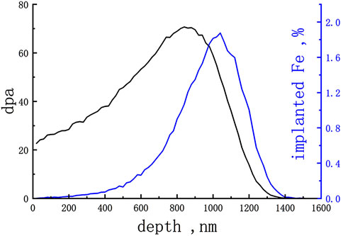
FIGURE 2. Damage (dpa) and implanted Fe ions distribution (%) along depth calculating by SRIM.
The dispersive nano-precipitates of small size and high number density account for the advanced mechanical property and resistance to irradiation void swelling of ODS steel. The distribution, structure, and chemical composition of oxide nano-precipitates are characterized and analysed as follows.
Nano-precipitates of high number density and near-uniform distribution were observed in TEM bright field in Figure 3A. Precipitate size distribution was calculated using TEM bright field images and more than 1000 precipitates were measured, as shown in Figure 3B. The size of oxide precipitates varies from about 1 nm in diameter to 20 nm. Most of the precipitates are under 10 nm and the average size is 3.5 nm. The thickness of the TEM specimen prepared by electropolishing was estimated to be 100 nm and the number density of oxide precipitates is 5 × 10²²/m3. The size and number density of the oxide precipitates in this ODS steel are the same levels as several kinds of ODS steels, with a number density of 1022–1024/m3 and an average size from 2 to 10 nm (Klimiankou et al., 2005; Aleev et al., 2011; Hirata et al., 2012; Wu et al., 2012; Rahmanifard et al., 2015; Liu et al., 2017).

FIGURE 3. (A) High-density oxide nano-precipitates inside a grain in TEM bright field. (B) Size distribution of nano-precipitates in the as-received sample.
Y2O3 powder was added to produce oxide precipitates and the expected structure of nano-precipitates is Y2O3. TEM images in Figure 4 show an oxide nano-precipitate with a diameter of 3.5 nm in the steel matrix together with its fast Fourier transform (FFT) image. A structure of Y2O3 (PDF#01-075-3096) in the direction of (0 2 2) can be seen. The d-spacings of 0.26 and 0.31 nm accord with the d-spacings of (4 0 0), (2 2 2) in Y2O3, respectively, and the corresponding angles are 73 and 53°. Structures of 10 nano-precipitates and their FFT were examined and all of them were the same Y2O3 structure. No specific orientation relationship between precipitates and the steel matrix was observed.
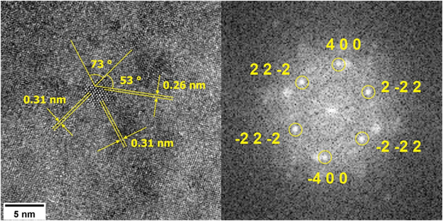
FIGURE 4. TEM image of an oxide nano-precipitate with a diameter of 3.5 nm together with its fast Fourier transform (FFT) image, showing a structure of Y2O3 (PDF#01-075-3096).
The chemical compositions of Y-O nano-precipitates acquired by EDS are shown in Figure 5. Precipitates vary from 1 to 10 nm in diameter in the HADDF image. These larger precipitates were chosen to illustrate element distribution clearly. Precipitates of Y and O, lacking Fe can be seen, and some of the precipitates contain Si and a small amount of Ta as well. A shell structure of V surrounding oxide is clearly demonstrated with the element map of Y and V. Element map of Cr shows its slight aggregation around the oxides.
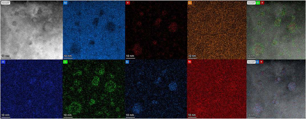
FIGURE 5. HADDF image and EDS elemental mappings showing the chemical compositions of oxide nano-precipitates and shell-core structures.
It has been reported that other trace elements, such as Mn, Si, V, and Ta, could take part in the formation of oxide nano-precipitates, and some of the precipitates with these minor elements have different structures instead of Y2O3. Uchidi et al. (2011) reported that in 9YWT ODS steel with an extra 1 wt% Si added, besides fine precipitates of Y2O3, complex oxide of Y2SiO5 appeared during the annealing process after MA. An atom probe tomography (APT) study of ODS-EURORFER 97 steel showed the presence of Mn and Si at both 5%–10% in oxide precipitates (Williams et al., 2010). Klimenkov et al. (2009) reported the presence of Mn inside nano-precipitates, with a chemical composition of (Y1.8Mn0.2)O3 of the oxides in ODS-EUROFER alloy by electron energy loss spectroscopy (EELS). Mn seemed to dissolve in the Y2O3 phase and the structure of oxides was not changed.
The presence of minor elements in oxide can be explained by the formation enthalpy of their oxides. Among all the minor elements in the MX-ODS steel in this study, the formation enthalpy of Y2O3 consuming per mole O at 298 K is 635 kJ, the largest, followed by SiO2 of 455 kJ, the second, and Ta2O5 of 409 kJ (Rumble, 2021). Oxygen prefers to form oxides with Y first during the fabrication process since it is the most stable oxide from thermodynamic perspectives. It is reasonable for Si to enter the oxide precipitates of Y and O as its formation enthalpy is the second highest. Considering the small amount of Si totally contained in the steel (only 0.0124 wt%), even though it has a different structure of binary oxide, Si in precipitates did not influence the structure of Y2O3 of nano-precipitates.
The presence of shell structure around the oxide nano-precipitates has been reported in several works of ODS EUROFER steels. ODS EUROFER steel has similar chemical compositions of minor elements with that of the MX-ODS steel used in this study and Y2O3 oxide nano-precipitates are observed in ODS EUROFER steel although the presence of large carbide is also present due to higher carbon content. A Cr and V-rich shell surrounding the oxide nano-precipitates of Y-O core or Ti-O particles was reported (Williams et al., 2010; Oksiuta et al., 2013; Fu et al., 2021). Klimenkov et al. (2009) suggested that a V-Cr-O shell of 0.5–1.5 nm thickness formed around oxide nano-precipitates. Besides, in the study of a model ODS alloy containing Fe-12Cr-0.4 Y2O3 wt%, a Cr-rich shell of 3 nm was found in some of the oxides, which were still present after annealing for 96 h (de Castro et al., 2011b).
The formation of the shell structure of V and Cr around nano-oxides can be explained by the following two reasons.
1) The originally formed oxides contained Cr and V and other minor elements besides Y, and in the following process at high temperature, V and Cr atoms were expelled from oxides due to their weaker bond with O atoms compared with the bonds with Y, Si, and Ta (Williams et al., 2010). With smaller formation enthalpy of V and Cr, they were adjacent to O in the oxide core as a shell structure. The distribution of elements inside oxide nano-precipitates and the shell structure around is the result of reaching lower energy locally. In the study by Aleev et al. (2011), instead of a V-shell around, V was found inside the oxide in ODS EUROFER characterized by ATP, and the concentration of V equaled or exceeded that of Y in some particles. This suggests that V atoms were concentrated in the oxides at one time, and might participate in the formation of oxides. Therefore the later expelling of V out of oxides could be possible.
2) The oxides originally formed with Y, and a small amount of Si, Ta, with V and Cr diffusing and segregating around oxides in the following process. Cr and V atoms have a relatively high diffusivity in bcc-Fe. The trace diffusion coefficients of V and Cr at 1150 K are in the order of 10−11 and 10−15 cm2/s, respectively, both higher than that of Fe, which is in the order of 10−15 cm2/s, but smaller than Cr (Choudhury et al., 2011; Obrtlik and Kuöeka, 2022). Segregation of Cr along grain boundaries was observed in some prior works (Zhou et al., 2016). The interface of oxides nano-precipitates and the steel matrix provides sites for segregation. The diffusion of these elements at high temperatures during fabrication resulted in their segregation around oxides.
Common carbides formed in steel such as MC, M23C6 (M = Fe, Cr, Mn) can be unstable during long-term high-temperature conditions and irradiation environments. The coarsening or dissolution of carbides results in the degradation of mechanical properties, threatening the safety of nuclear reactors (Grybėnas et al., 2017; Kano et al., 2018b). MX-ODS steel in this study was designed with extremely low carbon content to avoid the formation of carbides. Carbides were not found in the TEM examination of large areas in the electropolished specimens.
Two kinds of second phase precipitates of a rather large size (more than 40 nm in diameter) were found both on grain boundaries and inside the grains. The two types of large precipitates can be distinguished by their chemical composition and size.
The first type of large precipitates is the oxides of various metallic elements characterized as bright structures in the STEM images shown in Figure 6. The size of these oxides varies from 100nm to 250 nm and most of them contain Y, Ta, Si, thus named Y-Ta-Si oxide in this article. These oxides possess complex structures and some of them contain other elements such as Mn, Cr and V.
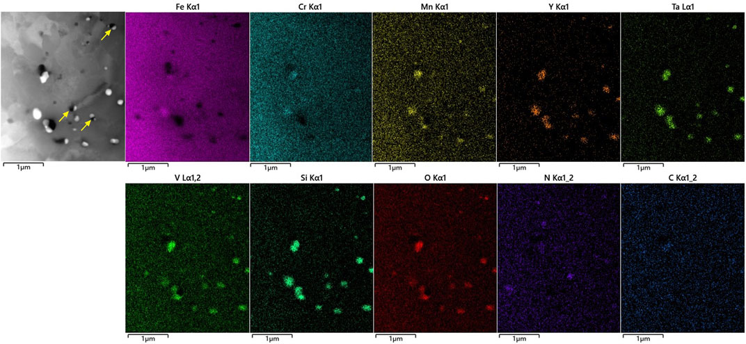
FIGURE 6. STEM image and elemental mappings of two types of large precipitates.
The second type of large precipitates is the VN particles characterized as dark structures in Figure 6. The size of VN particles is from 40 to 200 nm and the average size is smaller than 100 nm. It is noticed that some of the two kinds of large precipitates are present adjacent to each other, as indicated with arrows in Figures 6, 7 also shows a Y-Ta-Si-type oxide adjacent with VN, where the area of TEM image in Figure 8 is illustrated with a yellow box. The structure of VN is shown in Figure 8, with FFT of the TEM image in high magnification, in accord with VN (PDF#00-035-0768) in the direction of (0 2 2).
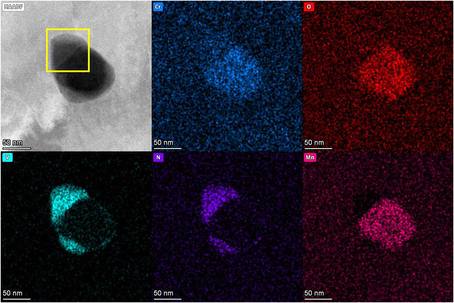
FIGURE 7. HADDF image and EDS elemental mappings of VN near an Y-Ta-Si type oxide. The area of TEM image in Figure 8 is illustrated with a yellow box.
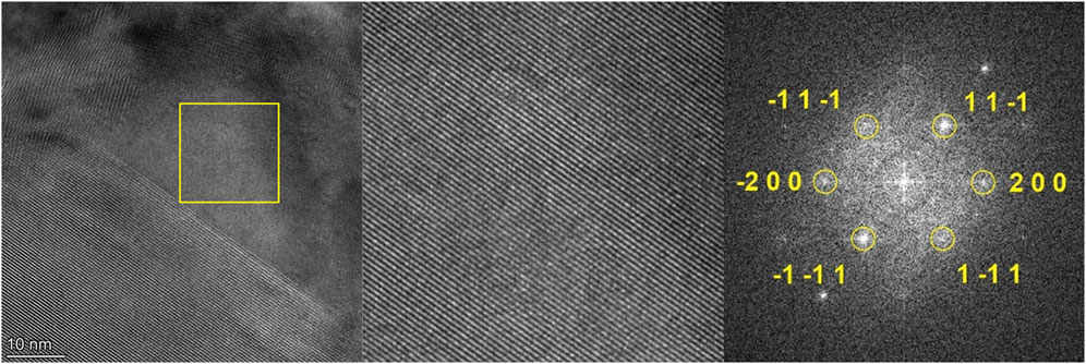
FIGURE 8. TEM bright field image of VN in high magnification, together with its FFT image showing a structure of VN (PDF#00-035-0768).
Voids of very small size (less than 1 nm) and high number density (about 1022/m3) were observed in the as-received specimen prepared by electropolishing, in the FIB specimen of unirradiated area, as well as in the area far from irradiation depth in the irradiated FIB specimen, using over focus and under focus in bright field TEM. Thus the presence of voids was not due to FIB preparation or high temperature during irradiation. Figures 9A, B show the voids in the as-received sample. The distribution of small voids was rather uniform and a preferred attachment of small voids to nano-precipitates was not observed.
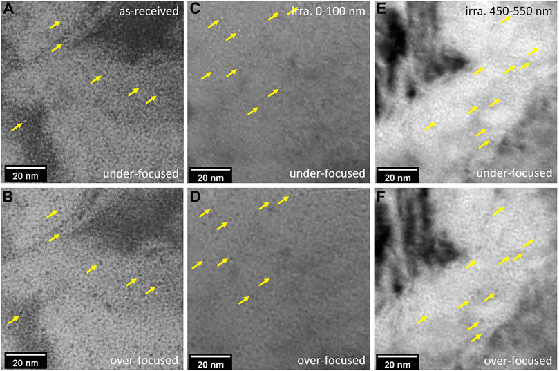
FIGURE 9. Voids in under-focused and over-focused TEM bright field. Some of the voids are illustrated with arrows. (A,B) Voids in the as-received sample. (C,D) Voids at the near surface area (0–100 nm in depth) of irradiated sample. (E,F) Voids in the irradiated sample in depth of 450–550 nm.
These pre-existing voids before irradiation were most probably produced during the hot forging and hot rolling process in the fabrication stage. Several works reported the presence of voids in ODS steel fabricated by the HIP process. It was reported that small voids of 2 nm in ODS-Fe12Cr or 5 nm in ODS-Fe14Cr alloys and voids were frequently found near oxide nano-precipitates, carbides, or Cr-rich precipitates (de Castro et al., 2009; de Castro et al., 2011a). Positron annihilation results of EUROFER steels with and without oxide dispersive strengthened particles suggested that Ar atoms were absorbed during the mechanical alloying process and vacancy clusters were captured by the interface between nano-precipitates and steel matrix, and hence, cavities nucleated grow next to precipitates (Ortega et al., 2008). The fabrication process of MX-ODS steel in this study included mechanical alloying in Ar atmosphere and hot forging as well as hot rolling instead of HIP. During the hot forging and hot rolling processes, materials were densified through rapid plastic deformation under high stress and the voids were not fully eliminated, thus small voids exist.
Oxide nano-precipitates were observed to be stable after high-temperature irradiation. Uniform distribution of fine and dense oxides was observed using HADDF as shown in Figure 10. The image was captured at the depth of 400 nm below surface, corresponding to a damage of about 35 dpa as calculated by SRIM. The oxides in the images presented an average size of about 3 nm in diameter and their chemical compositions are shown in EDS images. The nano-precipitates contained mainly Y and O, with Si not clearly seen inside these oxides. A shell rich in V is present clearly in the overlapped element maps of V and Y. Distribution of Cr shows a slight gathering around the oxide particles. It can be concluded that a shell-core structure remained and the composition of oxides did not change after irradiation, although a careful and detailed comparison of the shell-core structures before and after irradiation can be hard using EDS. The changes of oxide nano-precipitates after irradiation, such as coarsening or dissolution of oxides, have been widely studied, and in most cases, Y-O oxides remained stable after irradiation (Wharry et al., 2017). In this study, the oxide nano-precipitates in MX-ODS steel remained stable after self-ion irradiation, showing a good tolerance to irradiation.
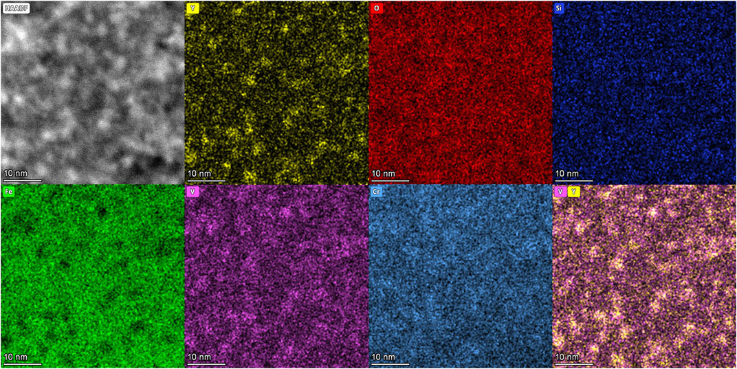
FIGURE 10. HADDF image and EDS elemental mappings of oxide nano-precipitates after irradiation, captured in the depth of 400 nm, corresponding to a damage of about 35 dpa.
Large precipitates became unstable after irradiation, showing an irregular shape instead of a perfect sphere. Due to the limited irradiated area in the FIB specimen and a relatively low number density of large precipitates, only three precipitates after irradiation were observed and characterized, as shown in Figure 11A. The three precipitates are at about 200, 300, and 900 nm in depth, respectively, corresponding to damage levels of 28, 33, and 70 dpa. The bright field images in Figures 11B, C and HADDF image in Figure 11D show the irregular shape of the precipitates, with several bulges attaching together and comprising the precipitates. The three large precipitates have crystal structures and contain various mantellic elements and O, N atoms. Figure 11E shows the elementary mapping of the precipitate in Figure 11D and it contains Cr, Mn, V, N, and O. Pure VN was not found in the irradiation affected area. These three large precipitates could be developed from Y-Ta-Si-type oxides and VN since they appeared adjacently as mentioned before. During irradiation, both excess point defects and displacement cascade account for the instability of precipitates. Binding between point defect and solute atom could lead to the dissolution of atoms in precipitates where point defect gradient occurs (Abe et al., 2014; Kano et al., 2018b), while a number of atoms may be ejected when a displacement cascade locates at least partly within a precipitate (Russell, 1993). Shape change of precipitates was most probably caused by dissolution and subsequent precipitation. Atoms were knocked off the precipitates and dissolved into the matrix in displacement cascades, then formed smaller precipitates clinging to the original one.
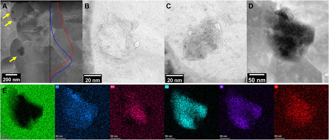
FIGURE 11. (A) HADDF image showing three precipitates in the irradiated area. Large precipitates are indicated with arrows and the dpa and implanted Fe ions distribution along depth are shown as lines in red and blue. (B,C) Bright field images of the upper precipitates. (D) HADDF image of the precipitates at the depth of damage peak. (E) EDS elemental mapping of the large precipitate in (D).
A much higher number density of voids appeared after irradiation in the irradiation influenced regions. As shown in Figure 9, voids are presented in bright and dark spots in under-focused and over-focused TEM bright field images. Images in Figures 9C, D were captured in the near-surface area, in the depth of 0–100 nm. Some of the voids are indicated with arrows in order to be clearly identifiable.
The size of voids remained small and statistics of their sizes can be fairly inaccurate, thus only numbers of voids in different depths were counted. A series of under-focused and over-focused TEM bright field images were captured along depth to calculate voids number density in different depths. A number density of 1022/m3 was calculated in the FIB specimen prepared in the unirradiated area. This statistics was set as a background to be subtracted when estimating voids distribution produced by irradiation.
The distribution of voids number density along depth, along with the irradiation damage and implanted ions distribution calculated by SRIM is shown in Figure 12. Voids of the largest number density, a number density of four times that of the unirradiated area, were observed at the depth of approximately 500 nm, shallower than the damage peak at 800 nm depth. Another area with a high number density of voids appeared at the surface of the sample, at a depth of about 50 nm.
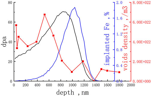
FIGURE 12. Distribution of voids density along depth with the irradiation damage and implanted ions distribution calculated by SRIM.
Void swelling due to irradiation was estimated using the number density of voids at 400–700 nm depth and an average size of 1 nm in diameter. Voids in the depth of 450–550 nm were shown in Figures 9E,F. Voids in this area was chosen to calculate void swelling in order to reduce implanted ion effects near peak damage area as well as to avoid the surface effect of the sample surface. The following formula (Velikodnyi et al., 2022) was used to calculate void swelling:
Where A and h stand for the area and the thickness of the images examined, di and Ni stand for the diameter of i-void and number of voids counted. The void swelling due to irradiation was only 0.004%, indicating a reasonably good resistance to void swelling during irradiation. Besides, the pre-existing voids seem not to grow to a larger size during irradiation.
Ferritic martensitic ODS steels present very small void swelling compared to steels without ODS structure (Shao et al., 2015). No voids were found or only 0.5% swelling occurred at peak damage under 50 dpa (Tanaka et al., 2004; Song et al., 2018). 0.05% and 1.5% swelling were found after self-ion irradiation up to 800 dpa at 475°C in tempered martensite and ferrite phases respectively (Chen et al., 2015). The void swelling calculated in this study is reasonable compared to previous observations by other researchers. The oxide nano-precipitates with high number density, small size, and uniform distribution contribute to the good void swelling resistance of ODS steels. A large number of vacancies and interstitials are produced during irradiation, resulting in a much higher concentration of point defects in the steel matrix. Some of the defects are captured by sinks such as dislocations, grain boundaries, and free surfaces, becoming immobilized or annihilated there (WAS, 2017). The diffusivity of interstitials is higher than that of vacancies, leading to the supersaturation of vacancies and hence the formation of voids. High-density nano-oxides act as trapping sites for defects and delay the supersaturation of vacancies, thus suppressing void swelling. The sink strength contributed by line dislocations, grain boundaries and oxide nano-precipitates were calculated and oxides contributed the most in ODS steels (Song et al., 2018). The ability of nano-precipitates to reduce freely migrating defects is even better than that of dislocations and grain boundaries according to a rate theory calculation (Liu et al., 2018).
The peak void number density appearing ahead of peak damage calculated by SRIM is due to the following two reasons. First, implanted Fe ions as extra interstitial atoms entered the matrix, reducing vacancy concentration by enhancing recombination between vacancies and interstitials and suppressing void density. Second, the irradiation was conducted at a relatively high temperature of 550°C, and the thermal diffusion was enhanced and depth-dependent radiation enhanced diffusion should be taken into consideration as well. The affected area of implanted Fe ions may expand to a wider range as suggested by Doyle et al. (2018). Thus, the peak void swelling area was observed prior to the peak swelling depth.
A high number density of voids appeared in the near-surface area because of a biased loss of interstitials to the surface. Planar sinks such as grain boundaries or free surfaces can cause local defect-depleted zones in irradiation since they capture free point defects (Zinkle and Snead, 2018). Both interstitial-type and vacancy-type defect clusters were found to deplete near surfaces (Gigax et al., 2016; Short et al., 2016). Interstitials diffuse faster than vacancies, resulting in a severe depletion of interstitials. Therefore, the void swelling was enhanced in the near-surface area.
A self-ion irradiation experiment was conducted on the MX-ODS steel and samples before and after irradiation were characterized using TEM. The following conclusions were obtained.
The MX-ODS steel in this study contains uniformly distributed oxide nano-precipitates of small size and high number density. The average diameter and number density of the nano-precipitates are 3.5 nm and 5 × 10²² /m3 respectively. The structure of fine oxides is Y2O3. Some nano-precipitates contain Si and present a V-rich shell surrounding Y and O. With an extremely low carbon continent, no carbides such as M23C6 or MC were found in the steel. Two types of large precipitates, Y-Ta-Si oxides, and VN, are present in grains and on grain boundaries, with a size of 100–250 nm and 40–200 nm respectively.
Heavy ion irradiation of 3 MeV Fe was conducted at 550°C to a peak damage of 70 dpa. After irradiation, fine and dense oxide nano-precipitates and their shell-core structure remained stable while large precipitates became instable, changing from globe to irregular shape with humps. Voids smaller than 1 nm appeared due to irradiation and the corresponding void swelling was only 0.004%, indicating a reasonably good swelling resistance of the MX-ODS steel in this study. The largest number density of voids occurred at the near-surface area and the depth ahead of peak damage calculated by SRIM, and this can be explained by the effects of implanted ions and the effects of surface.
The raw data supporting the conclusions of this article will be made available by the authors, without undue reservation.
YX and DY contributed to conception and design of the study. YX, DY, and XY analysed and discussed the results. YX wroted the first draft of the manuscript. DY reviewed and edited the manuscript. WY, YL, PZ, and CL provided and prepared the sample. CL and JL contributed to TEM characterization. TZ, JL, JZ, and LK conducted the irradiation experiment.
This work was supported by the State Key Research and Development Program of China, Grant No. 2020YFB1902100.
The authors declare that the research was conducted in the absence of any commercial or financial relationships that could be construed as a potential conflict of interest.
All claims expressed in this article are solely those of the authors and do not necessarily represent those of their affiliated organizations, or those of the publisher, the editors and the reviewers. Any product that may be evaluated in this article, or claim that may be made by its manufacturer, is not guaranteed or endorsed by the publisher.
Abe, H., Ishizaki, T., Kano, S., Li, F., Satoh, Y., Tanigawa, H., et al. (2014). Mechanism of instability of carbides in Fe–TaC alloy under high energy electron irradiation at 673K. J. Nucl. Mater. 455 (1), 695–699. doi:10.1016/j.jnucmat.2014.08.032
Aleev, A. A., Iskandarov, N. A., Klimenkov, M., Lindau, R., Möslang, A., Nikitin, A. A., et al. (2011). Investigation of oxide particles in unirradiated ODS Eurofer by tomographic atom probe. J. Nucl. Mater. 409 (2), 65–71. doi:10.1016/j.jnucmat.2010.09.008
Biersack, J. F. Z. J. P., SRIM Program, 2013 [Online]. Available: http://www.srim.org/[Accessed]
Chen, T., Aydogan, E., Gigax, J. G., Chen, D., Wang, J., Wang, X., et al. (2015). Microstructural changes and void swelling of a 12Cr ODS ferritic-martensitic alloy after high-dpa self-ion irradiation. J. Nucl. Mater. 467, 42–49. doi:10.1016/j.jnucmat.2015.09.016
Choudhury, S., Barnard, L., Tucker, J. D., Allen, T. R., Wirth, B. D., Asta, M., et al. (2011). Ab-initio based modeling of diffusion in dilute bcc Fe–Ni and Fe–Cr alloys and implications for radiation induced segregation. J. Nucl. Mater. 411 (1), 1–14. doi:10.1016/j.jnucmat.2010.12.231
de Castro, V., Leguey, T., Auger, M. A., Lozano-Perez, S., and Jenkins, M. L. (2011a). Analytical characterization of secondary phases and void distributions in an ultrafine-grained ODS Fe–14Cr model alloy. J. Nucl. Mater. 417 (1), 217–220. doi:10.1016/j.jnucmat.2010.12.067
de Castro, V., Leguey, T., Muñoz, A., Monge, M. A., Pareja, R., Marquis, E. A., et al. (2009). Microstructural characterization of Y2O3 ODS–Fe–Cr model alloys. J. Nucl. Mater. 386-388, 449–452. doi:10.1016/j.jnucmat.2008.12.136
de Castro, V., Marquis, E. A., Lozano-Perez, S., Pareja, R., and Jenkins, M. L. (2011b). Stability of nanoscale secondary phases in an oxide dispersion strengthened Fe–12Cr alloy. Acta Mater. 59 (10), 3927–3936. doi:10.1016/j.actamat.2011.03.017
Doyle, P. J., Benensky, K. M., and Zinkle, S. J. (2018). Modeling the impact of radiation-enhanced diffusion on implanted ion profiles. J. Nucl. Mater. 509, 168–180. doi:10.1016/j.jnucmat.2018.06.042
Fu, J., Davis, T. P., Kumar, A., Richardson, I. M., and Hermans, M. J. M. (2021). Characterisation of the influence of vanadium and tantalum on yttrium-based nano-oxides in ODS Eurofer steel. Mater. Charact. 175, 111072. doi:10.1016/j.matchar.2021.111072
Gigax, J. G., Chen, T., Kim, H., Wang, J., Price, L. M., Aydogan, E., et al. (2016). Radiation response of alloy T91 at damage levels up to 1000 peak dpa. J. Nucl. Mater. 482, 257–265. doi:10.1016/j.jnucmat.2016.10.003
Greenwood, L. R. S., and Smither, R. K. (1985). Specter: Neutron damage calculations for materials irradiations. RN:16073192. doi:10.2172/6022143
Grybėnas, A., Makarevičius, V., Baltušnikas, A., Lukošiūtė, I., and Kriūkienė, R. (2017). Correlation between structural changes of M23C6 carbide and mechanical behaviour of P91 steel after thermal aging. Mater. Sci. Eng. A 696, 453–460. doi:10.1016/j.msea.2017.04.103
Hirata, A., Fujita, T., Liu, C. T., and Chen, M. W. (2012). Characterization of oxide nanoprecipitates in an oxide dispersion strengthened 14YWT steel using aberration-corrected STEM. Acta Mater. 60 (16), 5686–5696. doi:10.1016/j.actamat.2012.06.042
Kano, S., Yang, H., Shen, J., Zhao, Z., McGrady, J., Hamaguchi, D., et al. (2018a). Instability of MX and M23C6 type precipitates in F82H steels under 2.8 MeV Fe2+ irradiation at 673 K. Nucl. Mater. Energy 17, 56–61. doi:10.1016/j.nme.2018.08.001
Kano, S., Yang, H., Shen, J., Zhao, Z., McGrady, J., Hamaguchi, D., et al. (2018b). Investigation of instability of M23C6 particles in F82H steel under electron and ion irradiation conditions. J. Nucl. Mater. 502, 263–269. doi:10.1016/j.jnucmat.2018.02.004
Kimura, A., Kasada, R., Iwata, N., Kishimoto, H., Zhang, C. H., Isselin, J., et al. (2011). Development of Al added high-Cr ODS steels for fuel cladding of next generation nuclear systems. J. Nucl. Mater. 417 (1), 176–179. doi:10.1016/j.jnucmat.2010.12.300
Klimenkov, M., Lindau, R., and Möslang, A. (2009). New insights into the structure of ODS particles in the ODS-Eurofer alloy. J. Nucl. Mater. 386-388, 553–556. doi:10.1016/j.jnucmat.2008.12.174
Klimiankou, M., Lindau, R., Möslang, A., and Schröder, J. (2005). TEM study of PM 2000 steel. Powder Metall. 48 (3), 277–287. doi:10.1179/174329005X64171
Lin, Y.-R., Chen, W.-Y., Tan, L., Hoelzer, D. T., Yan, Z., Hsieh, C.-Y., et al. (2021). Bubble formation in helium-implanted nanostructured ferritic alloys at elevated temperatures. Acta Mater. 217, 117165. doi:10.1016/j.actamat.2021.117165
Liu, X., Miao, Y., Li, M., Kirk, M. A., Zhang, G., Ukai, S., et al. (2018). Radiation resistance of oxide dispersion strengthened alloys: Perspectives from in situ observations and rate theory calculations. Scr. Mater. 148, 33–36. doi:10.1016/j.scriptamat.2018.01.018
Liu, X., Miao, Y., Wu, Y., Maloy, S. A., and Stubbins, J. F. (2017). Stability of nanoclusters in an oxide dispersion strengthened alloy under neutron irradiation. Scr. Mater. 138, 57–61. doi:10.1016/j.scriptamat.2017.05.023
Obrtlik, K., and Kuöeka, J. (2022). "Diffusion of vanadium in the Fe-V system, Phys. status solidi(a)Volume 53, Number 2 June 16, " ed. Görlich. De Gruyter), 589–597. doi:10.1002/pssa.2210530223
Odette, G. R. (2018). On the status and prospects for nanostructured ferritic alloys for nuclear fission and fusion application with emphasis on the underlying science. Scr. Mater. 143, 142–148. doi:10.1016/j.scriptamat.2017.06.021
Oksiuta, Z., Lewandowska, M., Kurzydlowski, K. J., and Baluc, N. (2013). Effect of vanadium addition on the microstructure and mechanical properties of the ODS ferritic steels. J. Nucl. Mater. 442 (1Suppl. 1), S84–S88. doi:10.1016/j.jnucmat.2012.10.022
Ortega, Y., de Castro, V., Monge, M. A., Muñoz, A., Leguey, T., and Pareja, R. (2008). Positron annihilation characteristics of ODS and non-ODS EUROFER isochronally annealed. J. Nucl. Mater. 376 (2), 222–228. doi:10.1016/j.jnucmat.2008.03.005
Rahmanifard, R., Farhangi, H., and Novinrooz, A. J. (2015). Effect of zirconium and tantalum on the microstructural characteristics of 12YWT ODS steel nanocomposite. J. Alloys Compd. 622, 948–952. doi:10.1016/j.jallcom.2014.11.018
Rui, X., Li, Y., Zhang, J., Wang, Q., Yan, W., and Shan, Y. (2022). Microstructure and mechanical properties of a novel designed 9Cr-ODS steel synergically strengthened by nano precipitates. Acta Metall. Sin. 0-0. doi:10.11900/0412.1961.2021.00534
Rumble, J. R. (2021). CRC handbook of chemistry and Physics. Boca Raton, FL: CRC Press/Taylor & Francis.
Russell, K. C. (1993). Phase instability under cascade damage irradiation. J. Nucl. Mater. 206 (2), 129–138. doi:10.1016/0022-3115(93)90120-N
Shao, L., Toloczko, M., Maloy, S., and Voyevodin, V. N. (2015). "Use of self-ion bombardment to study void swelling in advanced radiation-resistant alloys", in: Proceedings of the International Conference on Environmental Degradation of Materials in Nuclear Power Systems - Water Reactors. (Ottawa, Canada), August 2015
Short, M. P., Gaston, D. R., Jin, M., Shao, L., and Garner, F. A. (2016). Modeling injected interstitial effects on void swelling in self-ion irradiation experiments. J. Nucl. Mater. 471, 200–207. doi:10.1016/j.jnucmat.2015.10.002
Song, L., Yang, X., Zhao, Y., Wang, W., and Mao, X. (2019). Si-containing 9Cr ODS steel designed for high temperature application in lead-cooled fast reactor. J. Nucl. Mater. 519, 22–29. doi:10.1016/j.jnucmat.2019.03.029
Song, P., Morrall, D., Zhang, Z., Yabuuchi, K., and Kimura, A. (2018). Radiation response of ODS ferritic steels with different oxide particles under ion-irradiation at 550 °C. J. Nucl. Mater. 502, 76–85. doi:10.1016/j.jnucmat.2018.02.007
Stoller, R. E., Toloczko, M. B., Was, G. S., Certain, A. G., Dwaraknath, S., and Garner, F. A. (2013). On the use of SRIM for computing radiation damage exposure. Nucl. Instrum. Methods Phys. Res. Sect. B Beam Interact. Mater. Atoms 310, 75–80. doi:10.1016/j.nimb.2013.05.008
Tan, L., Byun, T. S., Katoh, Y., and Snead, L. L. (2014). Stability of MX-type strengthening nanoprecipitates in ferritic steels under thermal aging, stress and ion irradiation. Acta Mater. 71, 11–19. doi:10.1016/j.actamat.2014.03.015
Tan, L., Snead, L. L., and Katoh, Y. (2016). Development of new generation reduced activation ferritic-martensitic steels for advanced fusion reactors. J. Nucl. Mater. 478, 42–49. doi:10.1016/j.jnucmat.2016.05.037
Tan, L., Zhong, W., and Chen, T. (2020). Microstructural stability of tantalum-alloyed ferritic-martensitic steel with neutron irradiation to 7.4 dpa at ∼490 °C. Materialia 9, 100608. doi:10.1016/j.mtla.2020.100608
Tanaka, T., Oka, K., Ohnuki, S., Yamashita, S., Suda, T., Watanabe, S., et al. (2004). Synergistic effect of helium and hydrogen for defect evolution under multi-ion irradiation of Fe–Cr ferritic alloys. J. Nucl. Mater. 329-333, 294–298. doi:10.1016/j.jnucmat.2004.04.051
Tanigawa, H., Sakasegawa, H., Ogiwara, H., Kishimoto, H., and Kohyama, A. (2007). Radiation induced phase instability of precipitates in reduced-activation ferritic/martensitic steels. J. Nucl. Mater. 367-370, 132–136. doi:10.1016/j.jnucmat.2007.03.155
Toloczko, M. B., Garner, F. A., Voyevodin, V. N., Bryk, V. V., Borodin, O. V., Mel’nychenko, V. V., et al. (2014). Ion-induced swelling of ODS ferritic alloy MA957 tubing to 500dpa. J. Nucl. Mater. 453 (1), 323–333. doi:10.1016/j.jnucmat.2014.06.011
Uchidi, Y., Ohnuki, S., Hashimoto, N., Suda, T., Nagai, T., Shibayama, T., et al. (2011). Effect of minor alloying element on dispersing nano-particles in ODS steel. MRS Online Proc. Libr. 981 (1), 709. doi:10.1557/PROC-981-0981-JJ07-09
Ukai, S., Ohtsuka, S., Kaito, T., de Carlan, Y., Ribis, J., and Malaplate, J. (2017). “Oxide dispersion-strengthened/ferrite-martensite steels as core materials for Generation IV nuclear reactors,” in Structural materials for generation IV nuclear reactors. Editor P. Yvon (Sawston, Cambridge: Woodhead Publishing), 357–414.
Velikodnyi, A. N., Voyevodin, V. N., Kalchenko, A. S., Karpov, S. A., Kolodiy, I. V., Tikhonovsky, M. A., et al. (2022). Impact of nano-oxides and injected gas on swelling and hardening of 18Cr10NiTi stainless steel during ion irradiation. J. Nucl. Mater. 565, 153666. doi:10.1016/j.jnucmat.2022.153666
Wharry, J. P., Swenson, M. J., and Yano, K. H. (2017). A review of the irradiation evolution of dispersed oxide nanoparticles in the b.c.c. Fe-Cr system: Current understanding and future directions. J. Nucl. Mater. 486, 11–20. doi:10.1016/j.jnucmat.2017.01.009
Williams, C. A., Marquis, E. A., Cerezo, A., and Smith, G. D. W. (2010). Nanoscale characterisation of ODS–Eurofer 97 steel: An atom-probe tomography study. J. Nucl. Mater. 400 (1), 37–45. doi:10.1016/j.jnucmat.2010.02.007
Wu, Y., Haney, E. M., Cunningham, N. J., and Odette, G. R. (2012). Transmission electron microscopy characterization of the nanofeatures in nanostructured ferritic alloy MA957. Acta Mater. 60 (8), 3456–3468. doi:10.1016/j.actamat.2012.03.012
Zheng, P., Li, Y., Zhang, J., Shen, J., Nagasaka, T., Muroga, T., et al. (2020). On the thermal stability of a 9Cr-ODS steel aged at 700 °C up to 10000 h - Mechanical properties and microstructure. Mater. Sci. Eng. A 783, 139292. doi:10.1016/j.msea.2020.139292
Zhou, X., Yu, X.-x., Kaub, T., Martens, R. L., and Thompson, G. B. (2016). Grain boundary specific segregation in nanocrystalline Fe(Cr). Sci. Rep. 6 (1), 34642. doi:10.1038/srep34642
Zinkle, S. J., Boutard, J. L., Hoelzer, D. T., Kimura, A., Lindau, R., Odette, G. R., et al. (2017). Development of next generation tempered and ODS reduced activation ferritic/martensitic steels for fusion energy applications. Nucl. Fusion 57 (9), 092005. doi:10.1088/1741-4326/57/9/092005
Keywords: ODS steel, ion irradiation, void swelling, oxide nano-precipitate, MX phase
Citation: Xu Y, Yun D, Yan X, Zhang P, Yan W, Li Y, Li C, Li J, Zhang T, Li J, Zhou J, Kang L and Lu C (2023) Effects of Fe self-ion irradiation on a low carbon MX-ODS steel at 550°C. Front. Energy Res. 10:988745. doi: 10.3389/fenrg.2022.988745
Received: 07 July 2022; Accepted: 13 December 2022;
Published: 25 January 2023.
Edited by:
Muhammad Zubair, University of Sharjah, United Arab EmiratesReviewed by:
Zhangjian Zhou, University of Science and Technology Beijing, ChinaCopyright © 2023 Xu, Yun, Yan, Zhang, Yan, Li, Li, Li, Zhang, Li, Zhou, Kang and Lu. This is an open-access article distributed under the terms of the Creative Commons Attribution License (CC BY). The use, distribution or reproduction in other forums is permitted, provided the original author(s) and the copyright owner(s) are credited and that the original publication in this journal is cited, in accordance with accepted academic practice. No use, distribution or reproduction is permitted which does not comply with these terms.
*Correspondence: Di Yun, ZGl5dW4xOTc5QHhqdHUuZWR1LmNu
Disclaimer: All claims expressed in this article are solely those of the authors and do not necessarily represent those of their affiliated organizations, or those of the publisher, the editors and the reviewers. Any product that may be evaluated in this article or claim that may be made by its manufacturer is not guaranteed or endorsed by the publisher.
Research integrity at Frontiers
Learn more about the work of our research integrity team to safeguard the quality of each article we publish.