
95% of researchers rate our articles as excellent or good
Learn more about the work of our research integrity team to safeguard the quality of each article we publish.
Find out more
ORIGINAL RESEARCH article
Front. Energy Res. , 18 May 2022
Sec. Nuclear Energy
Volume 10 - 2022 | https://doi.org/10.3389/fenrg.2022.891105
This article is part of the Research Topic Experimental and Simulation Research on Nuclear Reactor Thermal-Hydraulics View all 15 articles
 Xiang Li1
 Lingyuan Gao2Caihong Xu2Ting Wang2
 Wan Sun1*Wen Zhu3
 Luteng Zhang1
 Zaiyong Ma1
 Longxiang Zhu1
 Liangming Pan1
Since the counter current flow limitation (CCFL) of the two-phase flow has an important influence on the safety analysis of the reactor, it is also of great significance to study some characteristics and flow pattern transitions of the two-phase flow. In order to explore the characteristics and influencing factors of two-phase counter current flow in the hot leg under the condition of the Loss of Coolant Accident, this research, using RELAP5 simulation calculation, analyzed the effect of the lengths of the flow path of the hot leg, the shapes of the upper outlet of the inclined pipe, and the shapes of the elbow connecting the horizontal pipe and the inclined pipe on the characteristics of the CCFL. This research also evaluated the limitation of the model. The simulation founded that under the same liquid flow rate, the longer the horizontal pipe, the lower the gas flow rate at the beginning of the counter current flow; the effect of the elbow on the CCFL was not great; compared with the sharp outlet shape, the
The Loss of Coolant Accident, a break in the loop boundary or a stuck safety valve, etc., causes the coolant from the loop to flow out of the loop area. Flow erosion in piping systems is a concern for many industrial practices. The driving pressure head of natural circulation depends on the density difference between the up and down sections of the loop. In this process, if the main pump of the first loop of the nuclear power station stops idling, the natural circulation begins to change into a single phase, and the system pressure gradually drops. At this time, a lot of gas phase may be generated by flashing at the top of the core due to the high pressure, and thus the density difference increases in the pipeline, and ultimately the ability of natural circulation increases. But the resulting steam flow into the heat transfer pipe may be condensed, and soon the pressure in the primary loop is reduced to the pressure in the secondary loop. If the natural circulation is interrupted, CCFL will occur, and the steam generated in the core will rise to the steam generator in the hot leg, be cooled by the secondary circuit, and then flow back down the pipe. Such counter current flow may take away some of the heat, as shown in Figure 1. In recent years, international scholars have carried out research on the characteristics of two-phase countercurrent flow in different pipeline systems. Among them, the two-phase countercurrent flow in the hot leg was studied by Siddiqul et al. (1986), Ardron and Banerjee (1986). Wongwises (1998) conducted a study of two-phase counter current flow in the hot leg of a PWR. Kang et al. (Hewitt et al., 1965) and Yu et al. (Chun et al., 2000), specifically studied the effect of liquid level in the hot leg on its CCFL characteristics. Murase et al. (2012) used the Fluent software to numerically simulate the CCFL in the hot leg, and to model the full-scale hot leg model and the 1/15 reduced-scale hot leg test piece respectively. For the full-scale hot leg model, the numerical calculation results were dimensionless. And they were in good agreement with the experimental data. But for the reduced size hot leg test piece model, the numerical calculation model underestimated the discharge fluid flow. Researchers have devoted great efforts to provide credible thermal-hydraulic system codes for the analyses of transients and accidents scenarios in nuclear power plants (Wang et al., 2021). And this paper mainly used RELAP5 for simulation calculation, and evaluated the CCFL model. Simultaneously, this paper studied the effect of the lengths of horizontal pipe, the shapes of the upper exit of inclined pipe, and the shapes of elbow connecting horizontal pipe with inclined on the characteristics of the CCFL.
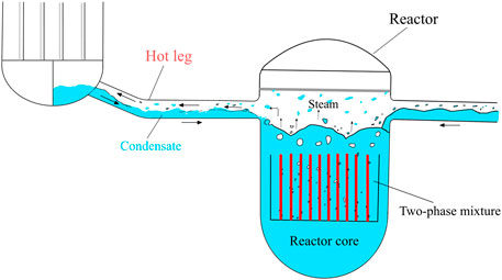
FIGURE 1. Counter current flow in the hot leg during the condensate flow back.
When LOCA occurs in a PWR, during the reflooding phase, the water collected at the steam generator inlet may flow back through the hot leg against the steam from the upper plenum, which creates a steam blockage in the primary loop. Among them, the counter current flow of water from the steam generator affects the accumulation of water and its horizontal distribution in the upper plenum, thereby affects the cooling of the multi-dimensional core, and the flow rate of water depends on the CCFL characteristics in the hot leg. In 1986, Akira (Ohnuki, 1986) conducted an experiment research in order to study the characteristics of CCFL in the model flow channel. This paper conducted a simulation study based on this experiment. The experimental system as shown in Figure 2. The cross section of the separator tank was a square of 0.21 m × 0.21 m and the height is 0.38 m. And the 0.03 m inner diameter water supply pipe located at the bottom of the measuring tank. The experimental section was visualized, and the separator tank was opened to the atmosphere. During the experimental procedure, to obtain an initial holdup of water in the separator tank, a continuous high flow rate of air was first supplied into the measuring tank. The water level h in the separator tank was kept constant during the experiment. When the air quality was constant
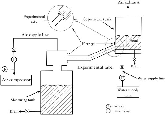
FIGURE 2. Schematic of experimental setup (Ohnuki, 1986).
Four pipe configurations were used in this study (Type A, Type B, Type C and Type D). Figure 3 to Figure 4 were schematic diagrams of the experimental pipes. In fact, the shape of upper exit of the PWR hot leg is a circular section. The shapes of elbow connecting the horizontal pipe and the inclined are smooth, and this section diameter is constant.

FIGURE 3. Schematic diagram of experimental Types A and B.
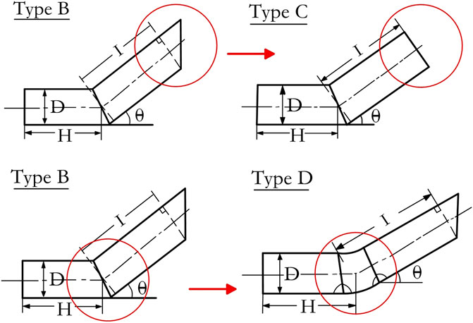
FIGURE 4. Schematic diagram of experimental Types C and D.
Type A was composed of inclined pipes only; Type B was composed of horizontal pipes connected to inclined pipes. Therefore, an improved pipe type was used instead of the Type B to study the effects of the shapes of upper exit and elbow. The shape of upper exit of Type C was a circular section, which was an improvement on Type B; Type D had a double-edged connection with the inclined pipe, which was an improvement to Type B, as shown in Figure 4. And Table1 shows the dimensions of the experimental section.
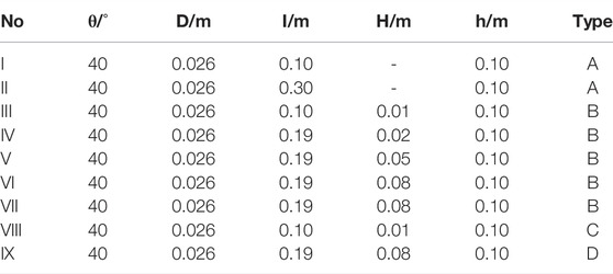
TABLE 1. Experiment section dimensions description.
Condition I, II and IV to VI carry out an analysis of the effect of lengths of horizontal pipe. Condition III and VIII pay attention to the effect of shapes of upper exit of inclined pipe. Furthermore, condition VII and IX focus on the effect of shapes of bend connecting horizontal pipe with inclined pipe.
The nodes division is shown in Figure 5. The inlet boundary, 210 and 310 components adopted the “TDV”; and the outlet boundary, 360 and 380 also adopted the “TDV”. Among them, 210 was used to simulate the air injection device, 310 was used to simulate the liquid injection, 360 was the exhaust port, and the 380 was used to maintain a constant water head in the separator. The horizontal and inclined pipe were simulated by “PIPE” 100.
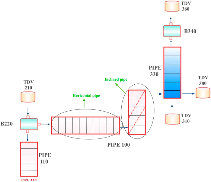
FIGURE 5. Nodes division diagram.
Noteworthily, in the modeling process, considering the difference in shapes of upper exit of inclined pipe, the simulation was carried out by changing the cross-sectional area of the exit, that was, Type A, Type B, and Type D were all calculated by elliptical area, and Type C was calculated by circular area, as shown in the Figure 6. As the Type D had a smooth bend connecting horizontal pipe with inclined, the nodes were refined to achieve a better simulation effect. At the same time, the influence of the coefficient of local resistance was considered at the joints of different elbows.
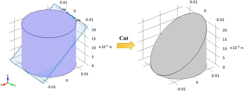
FIGURE 6. Schematic diagram of sharp incision in inclined pipe.
According to Figure 7, the area of the ellipse formed by the oblique cut is calculated as follows (in this study,
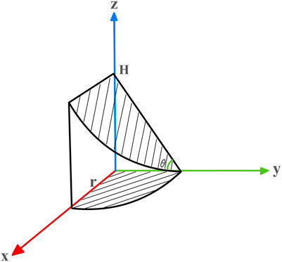
FIGURE 7. Coordinate chart for area calculation of sharp inclined pipe.
In the RELAP5/MOD3.3 program, if the CCFL model not turned on at the place where the gas-liquid counter current flow occurs, the “addition” and “subtraction” momentum equations are directly calculated simultaneously. Meanwhile, the program simulation do not take into consideration the effect of momentum loss caused by the instability of the liquid film; if the CCFL model turned on, this factor is considered.
The earliest Hewitt and Wallis (1963) passed the liquid down in a vertical acrylic resin tube with a diameter of 1.25 inch, and made the air flow up through the tube, in the opposite direction of the liquid, and then determined the minimum air flow rate required to cause the liquid to flow in the opposite direction upward. (that was, the flooding point), so obtain the empirical correlation related to CCFL.
Wallis number is a dimensionless number that characterizes the equilibrium relationship between momentum and static force. The following mainly analyzes the effect of the length H of the horizontal pipe, connecting the inclined pipe on the relationship between
where
The currently developed CCFL model has three main forms in the program: Wallis correlation, Kutateladze correlation, and the form between Wallis and Kutateladze correlation (Bankoff et al., 1981).
Classical relation:
where
The dimensionless fluxes of gas and liquid have the following forms:
where
where
By default, the Wallis correlation is used for small diameters and the Kutateladze correlation is used for large diameters. But the study of Tien et al. (Tien et al., 1979) believed that the correlations’ conditions should be more stringent and flooding data obtained from measurements of nuclear power plant geometry. Then, an appropriate CCFL model for the input cards is generated.
This part mainly discusses the influence of horizontal pipe length on CCFL of hot leg. It was found that the case of inclined riser without horizontal pipe,
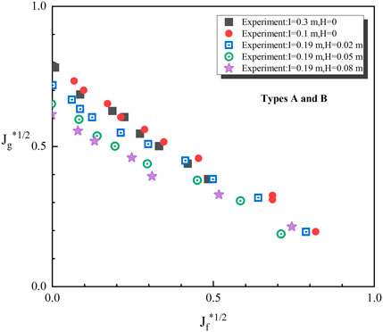
FIGURE 8. Influence of the horizontal pipe length (Ohnuki, 1986).
As follows, Figures 9, 10 showed the compares with the experimental data and RELAP5 simulation calculation data, respectively. It can be seen that the results calculated by RELAP5 are consistent with the change trend of the experimental data, but there are certain differences between the predicted data and the experimental data in some working conditions. If the pipe diameter and inclination angle of the inclined pipe remains constant in the hot leg, the initial flow rate keeps invariant, and the force between the gas and liquid phases and their effect maintains invariable. If the length of the horizontal pipe increases and the flow rate of the two phases remains unchanged, the action time and the distance between gas and liquid phases increases. And the gas phase consumes more energy in the liquid phase. Under the same liquid supply flow, a smaller air supply flow is required, the CCFL phenomenon occurs. It is worth noting that the “TDV” is used in the program calculation to specify the boundary conditions for the gas and liquid phase supply. In practice, if the pipe length is longer, the effect of gravity is magnified.
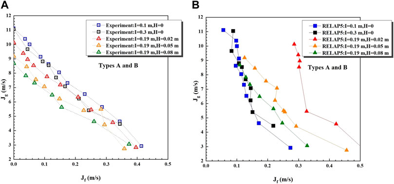
FIGURE 9. Summary of experimental and RELAP5 data (0.19 m long inclined pipe).
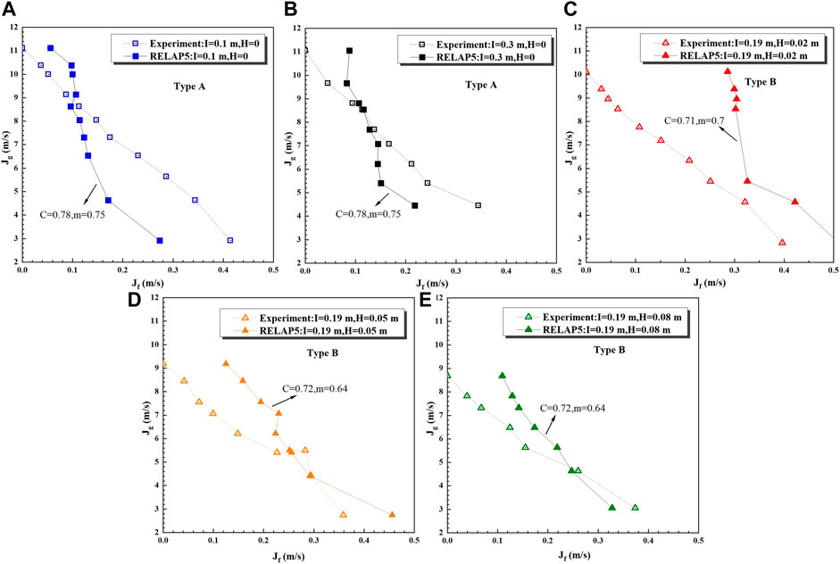
FIGURE 10. Effect of length of horizontal pipe.
This section primarily discusses the effect of shapes of bend connecting horizontal pipe with inclined on CCFL of hot leg. Figure 11 shows the effect of elbow shapes on the CCFL in experimental. The experimental data shows that the elbow shape had little effect on the CCFL, which is also reflected from the RELAP5 simulation results. Meanwhile, the trend of the simulated data is consistent with the experimental data, which is in good agreement. Due to the changes of the flow pattern of the two-phase flow at the junction of the horizontal pipe and the inclined pipe, the liquid in the elbow channel disturbs greatly at the junction, so it is easily carried by the gas flowing. This phenomenon becomes more obvious with the increase of liquid flow rate, which may affect the occurrence of CCFL phenomenon.
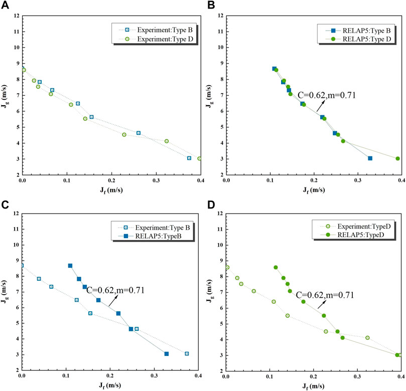
FIGURE 11. Effect of blow shapes.
Figure 12A shows the effect of different upper exit shapes of the inclined pipe on the CCFL experimental. Experimental data suggests that the upper exit shapes have an effect on CCFL, which are also reflected from the RELAP5 simulation results. Chung et al. (Tien et al., 1980) carried out an air-water CCFL test in a group of vertical pipes with the same pipe diameter and different outlet structures at the upper and lower ends. The lowest gas-phase flow rate occurs in the vertical pipe with the sharp-edged structure at the top; in the vertical pipe with the rounded top, the highest gas flow rate when CCFL occurs. Figures 12B–D have a similar situation in the inclined pipe. The
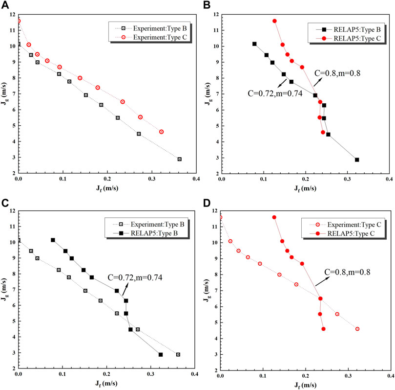
FIGURE 12. Effect of inclined pipe upper exit shapes.
Based on the simulation results in this paper, the following conclusions can be drawn:
1) Under the same water flow rate, the longer the horizontal pipe, the lower the gas flow rate at the beginning of the counter current flow. It should be noted that the program starts the CCFL model, nodes division in the vicinity of the connecting pipe should be as detailed as possible to reduce the program calculation error. And a single component can be added as a transition when simulating “TDV”.
2) The simulation results show that the elbow has little effect on the CCFL phenomenon. But with the increase of the liquid flow rate, the liquid disturbance increases, which affects the CCFL in the elbow.
3) The results show that the upper outlet shapes have the effect on CCFL characteristics. Compared with the sharp injection method, the gentle injection method is not easy to cause the initial disturbance of the liquid phase in the exit area, and the gas flow rate required to initiate the CCFL initiation under the same conditions is larger.
4) The above simulation results show that the CCFL model in Wallis correlation has good applicability, and the influence of pipe lengths and pipe orifice shapes on the characteristics of CCFL can be considered through the parameter fitting of c and m in the CCFL model. As long as the model aims to build at different geometric structures, the CCFL characteristics of different geometric structures can be well considered, but the input data of the determined model parameters are required in advance. It should be noted that the model of Wallis parameters comes from the fitting of experimental data with a small aperture geometry, and the modeling effect of the model needs to be considered for the large aperture experimental section in the nuclear reactor accident analysis.
In order to understand the influencing factors of the CCFL phenomenon in the hot leg more clearly, this paper mainly carried out the simulation of the effect of lengths of horizontal pipe, the effect of shapes of elbow and the effect of shapes of upper exit of inclined pipe. And this paper evaluated the CCFL model in the system program and analyzed the influencing factors. Simultaneously, some special considerations and solutions for modeling hot leg segments were given.
The original contributions presented in the study are included in the article/Supplementary Material, further inquiries can be directed to the corresponding author.
XL contributed the simulation work and also contributed the original writing and revision. LG, CX and TW contributed conceptions. WS provided experimental literature surveys and contributed constructive discussions. WZ, LuZ, ZM, and LoZ contributed review and suggestions. LP contributed the supervision of the study.
This work is financially supported by the National Key R&D Program of China (2018YFB1900400).
Authors LG, CX and TW are employed by Nuclear Power Technology Research Institute Co., Ltd.
The remaining authors declare that the research was conducted in the absence of any commercial or financial relationships that could be construed as a potential conflict of interest.
All claims expressed in this article are solely those of the authors and do not necessarily represent those of their affiliated organizations, or those of the publisher, the editors and the reviewers. Any product that may be evaluated in this article, or claim that may be made by its manufacturer, is not guaranteed or endorsed by the publisher.
Ardron, K. H., and Banerjee, S. (1986). Flooding in an Elbow between a Vertical and a Horizontal or Near-Horizontal Pipe. Int. J. Multiph. Flow 12, 543–558. doi:10.1016/0301-9322(86)90059-5
Bankoff, S. G., Tankin, R. S., Yuen, M. C., and Hsieh, C. L. (1981). Countercurrent Flow of Air/water and Steam/water through a Horizontal Perforated Plate. Int. J. Heat Mass Transf. 24 (8), 1381–1395. doi:10.1016/0017-9310(81)90188-5
Chun, M. H., No, H. C., Yu, S. O., Ghyym, S-H., and Sunf, C-K. (2000). “Effect of Initial Liquid Level on the Countercurrent Flow Limitation in a Horizontal Pipe Connected to an Inclined Riser[C],” in Proceedings of NTHAS2: Second Japan-Korea symposium on nuclear thermal hydraulics and safety, Japan (IAEA).
Hewitt, G. F., and Wallis, G. B. (1963).Flooding and Associated Phenomena in Falling Film Flow in a tube[R]. United Kingdom Atomic Energy Authority. Research Group. Harwell Berks, England: Atomic Energy Research Establishment.
Hewitt, G. F., Lacey, P. M. C., and Nicholls, B. (1965). “Transitions in Film Flow in a Vertical Tube[C],” in Symposium on Two-phase Flow, England (Exeter).
Murase, M., Tomiyama, A., Kinoshita, I., Utanohara, Y., Yanagi, C., Takata, T., et al. (2012). VOF Calculations of Countercurrent Gas-Liquid Flow in a PWR Hot Leg[J]. Sci. Technol. Nucl. Installations 2012, 935391. doi:10.1155/2012/935391
Ohnuki, A. (1986). Experimental Study of Counter-current Two-phase Flow in Horizontal Tube Connected to Inclined Riser. J. Nucl. Sci. Technol. 23 (3), 219–232. doi:10.1080/18811248.1986.9734975
Siddiqul, H., Banerjee, S., and Ardron, K. H. (1986). Flooding in an Elbow between a Vertical and a Horizontal or Nearhorizontal Pipe, Part I; Experiment. Int. Multiph. Flow. 12, 531–541.
Tien, C. L., Chung, K. S., and Liu, C. P. (1980). Flooding in Two-phase Counter Current Flows—II: Experimental Investigation[J]. Physicochem, Hydrodyn. 1, 209–220.
Wang, M., Wang, Y., Tian, W., Qiu, S., and Su, G. H. (2021). Recent Progress of CFD Applications in PWR Thermal Hydraulics Study and Future Directions. Ann. Nucl. Energy 150, 107836. doi:10.1016/j.anucene.2020.107836
Wongwises, S. (1998). Effect of Inclination Angles and Upper End Conditions on the Countercurrent Flow Limitation in Straight Circular Pipes. Int. Commun. Heat Mass Transf. 25 (1), 117–125. doi:10.1016/s0735-1933(97)00143-7
g gravitational acceleration (m·s−2)
D pipe diameter (m)
K nondimensional group depending only on fluid properties
L length of the lower limb of the elbow (m); Laplace capillary constant
Dj junction hydraulic diameter (m)
Greek symbols
ρk density (kg·m−3)
jk superficial velocity (m/s)
β constant
w feature length
Abbreviations
CCFL Counter current flow limitation
LOCA Loss of Coolant Accident
TDV Time Dependent Volume
RELAP Reactor Excursion and Leak Analysis Program
PWR Pressurized Water Reactor
Keywords: two-phase flow, RELAP5, counter current flow limitation, hot leg, LOCA
Citation: Li X, Gao L, Xu C, Wang T, Sun W, Zhu W, Zhang L, Ma Z, Zhu L and Pan L (2022) Research on Countercurrent Flow Limitation in Reactor Hot Leg at the Loss of Coolant Accident-Thermohydraulic Calculation With System Code RELAP5. Front. Energy Res. 10:891105. doi: 10.3389/fenrg.2022.891105
Received: 07 March 2022; Accepted: 21 April 2022;
Published: 18 May 2022.
Edited by:
Mingjun Wang, Xi’an Jiaotong University, ChinaReviewed by:
Hui He, Shanghai Jiao Tong University, ChinaCopyright © 2022 Li, Gao, Xu, Wang, Sun, Zhu, Zhang, Ma, Zhu and Pan. This is an open-access article distributed under the terms of the Creative Commons Attribution License (CC BY). The use, distribution or reproduction in other forums is permitted, provided the original author(s) and the copyright owner(s) are credited and that the original publication in this journal is cited, in accordance with accepted academic practice. No use, distribution or reproduction is permitted which does not comply with these terms.
*Correspondence: Wan Sun, c3Vud2FuQGNxdS5lZHUuY24=
Disclaimer: All claims expressed in this article are solely those of the authors and do not necessarily represent those of their affiliated organizations, or those of the publisher, the editors and the reviewers. Any product that may be evaluated in this article or claim that may be made by its manufacturer is not guaranteed or endorsed by the publisher.
Research integrity at Frontiers
Learn more about the work of our research integrity team to safeguard the quality of each article we publish.