- 1Key Laboratory of Power System Intelligent Dispatch and Control of Ministry of Education, Shandong University, Jinan, China
- 2Department of Electrical Engineering, Technical University of Denmark, Lyngby, Denmark
The coordinated optimization scheduling of the integrated energy systems is vital in multi-energy complementarity and hierarchical utilization. However, the centralized optimization is inferior to the distributed optimization of the large-scale multiregion integrated energy system (MRIES) in data processing capacity and information security. This study proposes a distributed computing architecture based on the edge computing unit (ECU), which takes the energy hub as the main body and sets the partitioning principle and method of MRIES. The ECU can finally realize the whole-system collaborative optimization of MRIES, which contains electrical, natural gas, and district heating networks through internal autonomous optimization and boundary information interaction with the cloud computing center. At the same time, an improved nested algorithm based on the consensus-alternating direction method of multipliers is proposed, which ensures the convergence of the mixed-integer linear program and effectively improves the convergence speed. Combining the advantages of the model and algorithm provides a theoretical and algorithmic support for the optimization research of the MRIES.
1 Introduction
Carbon peak and carbon neutrality targets put forward higher requirements for accelerating energy transformation in China. Therefore, the optimization of energy structure, energy conservation, and improvement of energy efficiency has become the most basic direction of energy development (Yunzhou et al., 2021). The construction of the IES is conducive to promoting the integration of source, network, load and storage, and multi-energy complementarity, which can realize the sustainable development for optimizing energy structure and improving energy efficiency. As the crucial part of IES research, RIES (Na et al., 2020) is mostly modeled in the form of EH. With EH as the main body, the RIES can be divided into functional units such as industrial areas, commercial areas, and residential areas. Based on the advantages of the geographical range, the RIES can conveniently realize the flexible optimization and scheduling decisions, which cannot be achieved without the assistance of multi-energy collaborative management, direct monitoring, and analysis of the operational data. Therefore, the RIES is an effective control and computing unit of IES intelligent evolution at present.
The IES distributed optimization has unique advantages over the centralized optimization in data acquisition cost, processing difficulty, application scale, information privacy, and security. A reasonable partition method of the IES and a suitable distributed algorithm are the fundamental problems of the IES distributed optimization. Haozhong et al. (2019) and Jianzhu Chen et al. (2019) used the different improved ADMM to conduct the distributed optimization of the IES based on the energy network decoupled. Jianzhu Chen et al. (2019) took CHP as the central part of the model and optimized the RIES in the distributed double layer, which took the delay of the bottom thermal ring network into account. In the study by Zhang et al., (2018), ADMM was adopted to optimize the pricing strategy of the multi-EH system with the underlying heating network. In the studies by Chen et al. (2018) and Chen et al. (2021), the static and dynamic characteristics of the EHs were taken into consideration and optimized, respectively. Zhang et al. (2018) proposed a multi-agent bargaining learning method, which optimized the large-scale IES in a distributed way, while the EH worked as the agent. Based on C-ADMM, Xu et al. (2019) improved the algorithm and analyzed the MRIES consisting of electrical, gas, and thermal three-ring networks with the four EHs. In comparison, Wen et al. (2017) used an improved method based on the C-ADMM dealing with the distributed optimization of a large-scale electric-gas system. ADMM was used for the distributed optimization of the multi-agent IES in the study by Haitao et al. (2021). Wu et al. (2020) used a hierarchical optimization method to carry out the distributed optimization of the electric–thermal system.
At present, the distributed collaborative optimization of the MRIES still has shortcomings:
(1) The role of MRIES in energy management and allocation is weakened by the decoupling method based on the different energy networks, which will be more complicated with the increase of the number and types of coupling devices.
(2) The distributed optimization with the EH as the main body does not consider the upper and lower energy network constraints. As a result, the global optimal solution cannot be obtained directly through the data interaction between the EHs.
(3) There is lack of a suitable distributed algorithm considering the EH off-design performance to support the expansion of the MRIES.
Therefore, this study proposes a distributed computing architecture based on an ECU and develops an IES partitioning method corresponding to it. And then, this study puts forward an improved algorithm adapted to the distributed characteristics of the model, forming a complete set of distributed computing methods based on ECU.
With the EH as the main body, the ECU is equivalent to RIES in geographical scope and structural level. The global optimal scheduling scheme is finally obtained through optimization within the unit and information interaction with the cloud. This architecture not only protects the information privacy and security of the RIES but also dramatically reduces the pressure of data transmission, storage, and processing in the cloud through edge computing, which reduces the difficulty of processing complex data of the IES. In addition, this study proposes a set of IES partitioning methods according to the connected positions of the EHs to reasonably partition ECU regions and provide a model basis for algorithm improvement. Based on the detailed RIES model, the improved C-ADMM nested algorithm fits the ECU model well, which can solve the nonconvergence problem caused by MISOCP and guarantee the optimization results with fewer iterations. They complement each other and provide a theoretical and methodological support for the MRIES distributed cooperative optimization.
In this article, the concept of the proposed ECU, modeling method, and improved algorithm are introduced in detail, and an example of the MRIES is used to verify the scalability and effectiveness of them.
2 Edge Computing Unit Framework for IES Distributed Optimization Scheduling
Internet of things, cloud computing, edge computing, and other technologies have played an important role in smart home management (Albataineh et al., 2020), power market (Chen S. et al., 2019), smart grid (Liu et al., 2021), (Cao et al., 2019), and other fields, but they have not fully emerged in the IES. Therefore, the ECU model proposed in this article will serve as a new energy management framework and provide a new idea for the unified management and coordinated scheduling of the IES multiple energy sources.
2.1 Framework of Edge Computing Unit
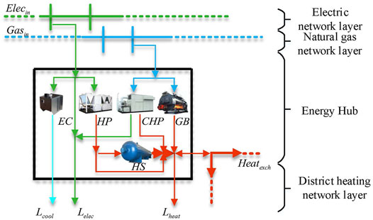
Corresponding to the cloud computing center in the IES, the ECU proposed in this article is the local energy data management unit, which can reduce cloud computing burden by finishing a part of the computing tasks at the local (Weisong et al., 2017). The structure of the ECU model presented in this article is shown in Figure 1.
EC, HP, CHP, and GB, as the coupling equipment convert power and natural gas into cold, heating, and power. Cooling and power are directly supplied to the local load, while the heating is transmitted to the HS or the DHN to jointly support the heating demand of the local load.
The modeling method of the upper radiant heat network is similar to that of the power grid and natural gas network. Therefore, the ring heating network is only established at the lower layer in this study for heat circulation. The ring network has high security and reliability (Wang et al., 2016), and the computing method for the ring network also meets the requirements of the radial heating network.
The ECU supports the multizone expansion, where the units are connected to each other through a power grid, natural gas network, and DHN, becoming the main body of the MRIES.
2.2 Data Exchange Process of Optimization Scheduling in Multiregion Integrated Energy System
The ECU obtains the data of the devices and nodes through the local awareness layer and submits the boundary information to the cloud after internal optimization. Then, the cloud feeds back the consensus information obtained from the centralized computing to each ECU. After that, the ECU adjusts the internal operation according to the consensus information. The MRIES achieves global optimization through several iterations.
The centralized optimization needs to submit all the device data to the cloud, which results in vast costs of communication facility construction, data transmission, storage, and processing. It deviates from the energy development idea of energy conservation and emission reduction. Meanwhile, the information security and privacy cannot be guaranteed, as shown in Figure 2A.
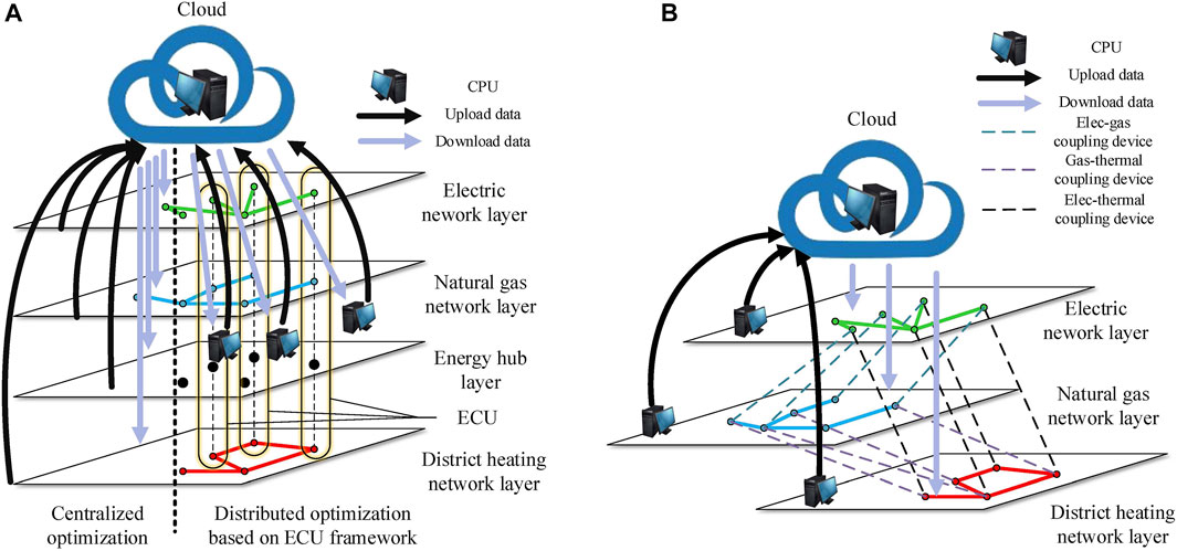
FIGURE 2. Data flow of different optimization methods in IES. (A) Data flow of the centralized optimization and the ECU architecture distributed optimization. (B) Data flow of the distributed optimization decoupled according to energy networks.
Figure 2B shows the distributed optimization based on the energy system decoupled. Each computing unit needs to process the data of the whole system, which is the mainstream distributed computing method at present. Although the amount of cloud workload is reduced by two to three times, it is still affected by the wide geographical range of the MRIES. Meanwhile, the cost of the communication facility construction is still relatively high. In addition, this method deconstructs the EH model, resulting in the separate operation of each coupling device. As the number and types of the coupling devices increase, the computational complexity of this method will increase and the cost of data transmission and storage will also increase significantly.
The decoupled method based on the ECU is shown in Figure 2A, where the data are transmitted within the RIES and only submits the boundary information at the coupling point between the ECUs to the cloud. This decoupled method dramatically reduces the cost of communication facility construction, data transmission, storage, and processing, while ensuring the security and privacy of the data. Furthermore, the ECU collects the data of three types of energy and processes them in a centralized manner, which can better play a synergistic role in optimization. In addition, this method lays a foundation for future research work of the unified energy management.
3 Modeling of the Edge Computing Unit
3.1 IES Decoupled Principle Based on Edge Computing Unit
As previously mentioned, EH is the main body and the energy management unit of the RIES. Therefore, the EH serves as the main body of the ECU to decouple the energy system. The partition principle should be based on the whole system’s lowest communication cost. The communication cost is proportional to the physical distance between the nodes. Therefore, we decouple the energy networks separately according to the adaptive method of P-median problem as shown in Eq. 1.
The objective function minimizes the information transmission distance within the network partitions, while the constraints ensure that the nodes are completely partitioned without repetition and omission. The IES model contains an electrical network, natural gas network, and DHN in the study. Therefore, the objective function should be applied in the three networks. After that, we can get the indices of the nodes in each unit of every network, but we need to further determine the boundaries between the units to provide the boundary data for cloud computing. As a result, section 3.2 provides a decoupled method to distinguish the boundaries between the units under different EH connection conditions.
3.2 IES Decoupled Method Based on the Edge Computing Unit
As previously mentioned, the units contain different nodes but are connected by an energy transmission line. The transmission line also falls within the scope of unit internal optimization, so the virtual node needs to be inserted into the transmission line to establish clear boundaries between the units and serve as a data collection point of the connecting transmission line.
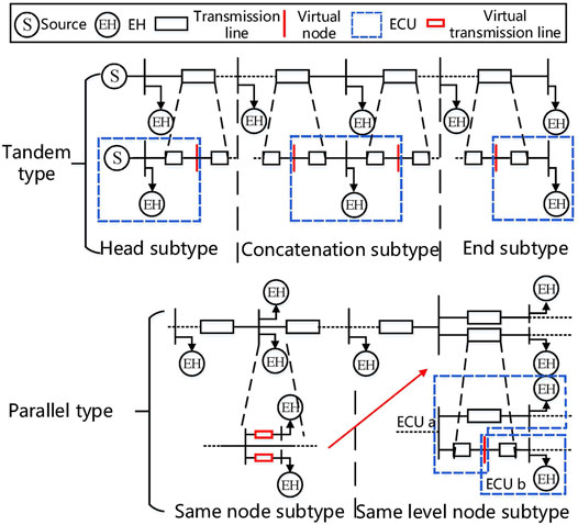
This study proposed a decoupled method, where the EH serves as the core in each ECU. Based on the connected position of the EH to the energy network, the whole system is decoupled by the partition method as given below. In Figure 3, the source represents the source of the energy network, which is the generator in the electrical network and the compressor in the natural gas network. EH represents a real hub. The virtual node is located in the middle of the transmission line, and the node data are the energy data in the middle of the transmission line. The virtual transmission line is lossless, aiming to reduce the coupling degree between the nodes.
3.2.1 Tandem Type
This type refers to the nodes of the EHs that are series nodes in the network. It contains three subtypes, such as the head subtype, concatenation subtype, and end subtype.
The concatenation subtype refers to the condition where the node of the EH is neither the end nor the head in the network. In this condition, the energy transmission line should be split in the middle and inserted with a virtual node on each side of the EH. The virtual node is included by the ECUs on both sides, and the insertion position of the virtual node is the boundary between the units. The data of the virtual node during the local optimization within the ECU are the boundary information submitted to the cloud.
The head/end subtype refers to the condition where the node of the EH is the head/end in the network. In this case, a virtual node should be inserted into the middle of the transmission line on only one side.
3.2.2 Parallel Type
This type contains two subtypes: same node subtype and same level node subtype, which, respectively, mean the EHs connected to the same nodes and the same level nodes in the network, as shown in Figure 3. When dealing with the same level node, a virtual node is inserted in the middle of one transmission line to transform it to the end subtype. As for the same node subtype, these node data for the EHs couple tightly, so a section of virtual transmission line should be added before each EH, which is transformed into the same level node subtype.
The energy networks are decoupled based on the abovementioned methods. The total energy consumption of a single ECU is the amount of the difference between the inflow and outflow.
3.3 Electrical Network Model in the Edge Computing Unit
In this study, the Distflow model is used to simulate the power flow of the distribution network in the ECU (Baran and Wu 1989), and the SOCP is used to deal with the nonlinear model. The power balance of the node described in Eqs 2–4 is the voltage loss equation, and Eq. 5 represents the relationship between the branch current, node voltage, and power.
The capacity limitation of the transmission line is shown as Eq. 6.
Power consumption of the ECU is shown as Eq. 7.
3.4 Natural Gas Network Model in the Edge Computing Unit
The natural gas network model in the ECU is similar to the electrical network, including the node energy balance constraint and pipeline transport constraint. Eq. 8 represents the balance between the inflow and outflow of node b.
The natural gas network in this article is a medium–low pressure network without considering the compressor model (Hu et al., 2020). The second-order cone programming is used to relax the Weymouth equation of the natural gas network, as shown in Eq. 9 (Liu et al., 2020). Eqs 10,11 are the upper and lower limits of the gas transmission volume and natural gas pressure of the pipeline, respectively.
The natural gas consumption of the ECU is shown as Eq. 12.
3.5 DHN Model in the Edge Computing Unit
This study uses the available heating Hav to describe the thermal flow in a pipe. Two strong-coupled variables, temperature T and mass flow q in the DHN model are decoupled to form the thermal flow network model and the basic flow-temperature equation.
The linearized heat loss equation shows as Eq. 14, and Wei et al., (2017) prove that it has good accuracy when the initial temperature is 88 ∼92°C. Section 4.2 will introduce the improved distributed algorithm based on linear heat loss.
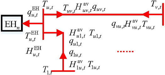
The setup of the reference direction of heating medium flow in the DHN is shown in Figure 4. The EHn represented the nth EH. The thermal flow network model is shown as Eq. 15.
A mixed-integer model of the thermal flow network is established based on the abovementioned equation to obtain the available heating distribution. Combined with the basic flow-temperature equation below, we can calculate the transmission temperature and thermal flow in the pipe.
The DHN operation cost is caused by the operation cost of circulating water pumps in the network. Therefore, the EHR is introduced to describe the cost of the circulating water pumps. Eq. 17 represents the heat network operation cost of the nth ECU. Each pipe is configured with a circulating water pump in this study.
3.6 EH Model Considering Off-Design Performance
The EH is the energy conversion main body of the ECU. In this article, the standard matrix model is adopted for the EH model (Wang et al., 2017), and the piecewise linearization method is used to improve the accuracy of the EH model (Huang et al., 2019).
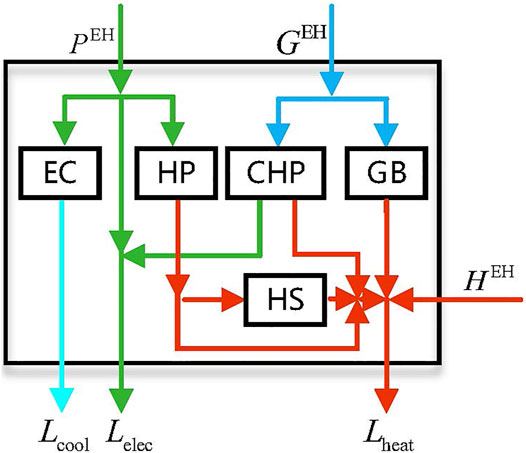
The energy flow direction of the coupling equipment is shown in Figure 5. Eqs 18–20 describe the standard model of the EH. The heating output from the EH and the heating obtained from the DHN jointly support the heat load in this region.
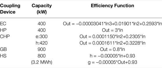
To simplify the nonlinearity of the coupling equipment efficiency, this study uses the piecewise linearization method as shown in Eqs 21–23 dealing with the nonlinear efficiency function of the coupling devices instead of the constant efficiency.
3.7 Objective Function of the Edge Computing Unit
The model of the ECU has been completed. The internal power grid and the natural gas network build up the SOCP, while the DHN and EH build up the MILP problem. This study takes the minimum economic cost as the optimization objective, and the objective function and the constraints of each ECU are shown in Eq 24.
4 Nested Algorithm Based on C-ADMM
The ADMM algorithm performs well in the distributed optimization and has many improved forms. The multiregion expansion form of the standard ADMM, which guarantees convergence, is complex and does not conform to the calculation form of the ECU proposed in this article (Wang et al., 2013). The GS-ADMM cannot guarantee the convergence of multiregion expansion when n ≥ 3, which is in the form of a serial computation (Ma et al., 2016). The C-ADMM supports the multizone expansion and is a parallel computing form, so it is used as the improved basis of the distributed algorithm in this study.
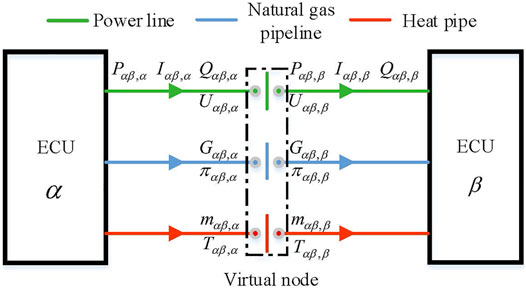
It is the key to coordinate the consensus information for the C-ADMM. The ECUs connect with each other through the power line, natural gas pipeline, and heat pipe as shown in Figure 6. The coupled information includes P, Q, I, U of the power line, G, π of the natural gas pipeline, and H of the heat pipe, which has an equality relationship with the consensus parameters at the virtual node as shown in Eq. 25.
According to Eq. 24, the Lagrange expansion of the C-ADMM is shown in Eq. 26. Eq. 27 is used to update the consensus variables and penalty factor.
In order to ensure the convergence of the optimization problems with discrete variables, previous work improved the C-ADMM algorithm, such as solving the MISOCP nonconvergence caused by the ring natural gas network through the nested computation of the discrete variables relaxation (Wen et al., 2017). The nonconvergence problem was solved by embedding the NC-ADMM method into the subproblem (Chen et al., 2020).
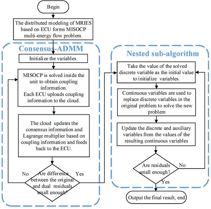
In order to ensure the convergence of the MISOCP constituent, a nested subalgorithm was added to the C-ADNN algorithm in this article, as shown in Eq. 28. The additional increment term describes that all the ECUs support transmission loss of the DHN which can constrain the direction of each iteration and improve the convergence speed, while the loss linearization of the heat network is the premise of this improvement. The algorithm flow chart is shown in Figure 7.
The nested subalgorithm is introduced as given below.
Step 1. Initializing the discrete variables B, k, and θ. Setting the error tolerance δ.
Step 2. Combining Eqs 2–16 and Eqs 18–23 to solve Eq. 29 and then obtaining the value of CB, before which the unknown variable CB takes place of the discrete variable B.
Step 3. Updating the discrete variables B and auxiliary variables zB as shown in Eq. (30).
Step 4. Comparing the error obtained by Eq. 29 with δ. If the error is little enough, the iterative process will be broken, and if on the contrary, steps two to four will be repeated.
The addition of the nested subalgorithm makes the solution approach the feasible region infinitely. When the difference between the original and the dual errors of the original problem is small enough, the convergence process can be sped up significantly.
5 Case Study
5.1 System Description
According to the partition method, the insertion of virtual nodes into the energy networks and partitioning them is based on the principle stated in section 3.1. The ECUs can completely contain all the nodes without repeat, as shown in Figure 8A. The partition details are shown in Figure 8B.
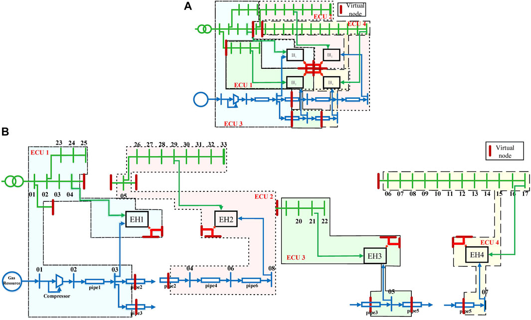
FIGURE 8. MRIES partition based on ECU. (A) Overall partition of MRIES. (B) Partition details of MRIES.
This article uses the improved C-ADMM algorithm to complete the distributed optimization of the MRIES in two scenarios.
Scenario A: Optimizing the MRIES containing electrical, gas, and heating networks based on the ECUs.
Scenario B: Optimizing the MRIES containing the electrical and natural gas networks based on the ECUs.
In both the scenarios, the MRIES have the same loads. Nevertheless, in Scenario B, the coupling equipment produces the heating to meet the heating demands.
Conversion efficiency functions of the coupling devices are shown in Table 1. The types of coupling devices in the MRIES are shown in Table 2. The energy prices and loads of each EH are shown in Figure 9.
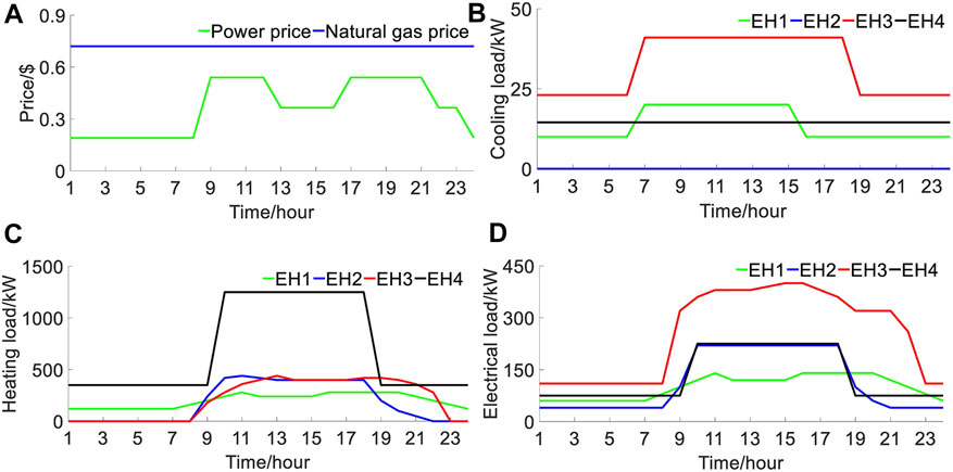
FIGURE 9. Model data of MRIES. (A) Energy price of system. (B) Daily cooling load of each EH. (C) Daily heat load of each EH. (D) Daily electrical load of each EH.
The codes were written in MATLAB 9.4.0.813654 (R2018a), and all the experiments were conducted on a desktop with 3.00 GHz Intel Core i5 and 16.0 GB RAM.
5.2 Analysis of Optimization Results
The improved algorithm proposed is used to optimize this MRIES in this article. The energy inputs to the equipment of the four ECUs in the different scenarios are shown in Figure 10.
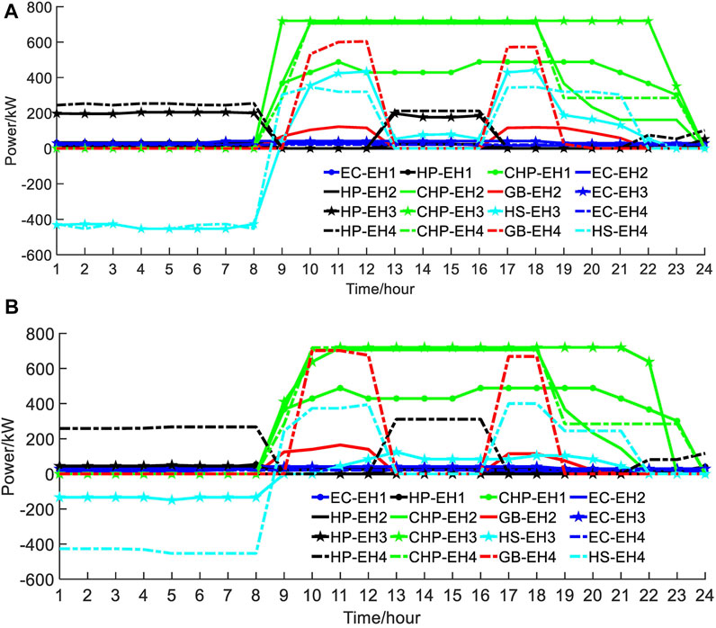
FIGURE 10. Energy input of each equipment. (A) Energy input of each equipment in scenario A. (B) Energy input of each equipment in scenario B.
As shown in Figure 10A, to support the heating load concentrated in midday, the HP is constantly working during low loading time of energy consumption when the power is cheaper. The heating is stored in the HS at night, which releases when the electricity price is high. In addition to this, the GB supports the remaining heating demand. Since there is no GB in EH3, it can only generate heat through the CHP. Furthermore, EH3 has the largest electric load at midday. As a result, the CHP runs at full capacity at all the time. In addition, the CHPs in EH2 and EH4 also run at full capacity at midday when the electric and heating load is large. On the other hand, the electric and heating load is relatively small in EH1. Therefore, the CHP is mainly used for power and heating supply in the peak load period, and the HP will start up for heat supplement during the flat power demand period.
As shown in Figure 10B, EH4 uses HP and GB with a high cost to supply heat due to the lack of DHN for heat exchange in scenario B. EH3 no longer needs to provide the heating to the DHN, which produced significant heating in scenario A. As a result, the utilization rate of HP and HS becomes lower. The overall energy cost response of the MRIES weakened in scenario B.
The heating generated by the EH, which is beyond the local heating load, is transmitted to the DHN. As shown in Figure 11, the energy represented by the blue block is equal to the energy of other color blocks higher than the heat load line (except the purple block that indicates heating storage). It should be noted that for the intuitive description, the load curves in Figure 11 are superimposed of electricity, gas, and heating load curves.
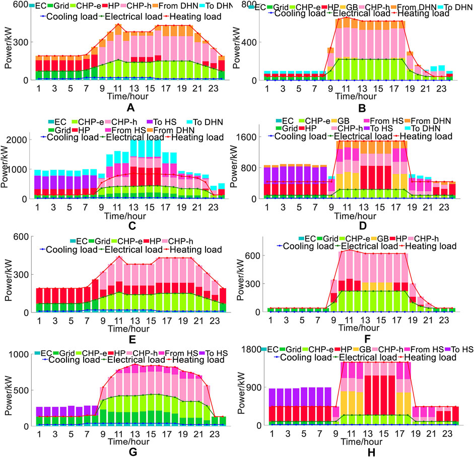
FIGURE 11. Energy components of the EHs in scenario A and B. (A) Energy components of EH1 in scenario A. (B) Energy components of EH2 in scenario A. (C) Energy components of EH3 in scenario A. (D) Energy components of EH4 in scenario A. (E) Energy components of EH1 in scenario B. (F) Energy components of EH2 in scenario B. (G) Energy components of EH3 in scenario B. (H) Energy components of EH4 in scenario B.
Because the coupling of the ECU in the electric network and natural gas network is only reflected in energy transmission, the energy interaction of each ECU in the DHN is mainly analyzed. The energy outputs of each EH device and the energy interaction with the DHN are integrated into Figures 11A–D. Evidently, the DHN realizes the heating interaction between the ECUs and dramatically increases the flexibility of energy utilization of the system. In scenario A, the EH1 internal equipment composition is relatively simple, which mainly absorbs the heat from the DHN. Although EH4 has many types of internal heat generation equipment, it still mainly absorbs the heat from the DHN due to its large heating load.
From Figure 11E–H, we can see that the heating support of EH3 is significantly reduced in scenario B. EH1, EH2, and EH4 have to convert energy through the coupling equipment in their units to meet the local loads, confirming the previous analysis conclusion. The total energy cost of scenario A is 12,281.24 dollars while that of scenario B is 15,234.56 dollars. For now, we can get the importance of the multi-energy cooperative scheduling.
5.3 Comparison of Algorithm Performance
The accuracy and convergence performance of the algorithm proposed are improved in this article. As analyzed previously, the improved algorithm can realize the MRIES global optimization through the unit internal optimization and information interaction between the units. The distributed optimization is not based on the whole system data; it can only approach the result of the centralized algorithm infinitely but cannot be better than that, and the insufficient iteration of the MISOCP will aggravate this error. The centralized algorithm which optimizes based on the whole system data can provide a precision reference for the improved distributed algorithm. The improved C-ADMM algorithm in this article adds the nested subalgorithm, which can not only overcome the nonconvergence problem caused by the MISOCP but can also approach the feasible region more closely than the C-ADMM algorithm, making the results more accurate. The results of the centralized algorithm, C-ADMM algorithm, and improved C-ADMM algorithm are shown as Table 3. The total energy cost error of the improved C-ADMM algorithm is about 0.1%. In contrast, the error of the C-ADMM algorithm is about 1.3%. In addition, the electricity and gas cost error are also relatively less. This shows that the improved algorithm proposed in this article achieves better optimization results than the original C-ADMM.
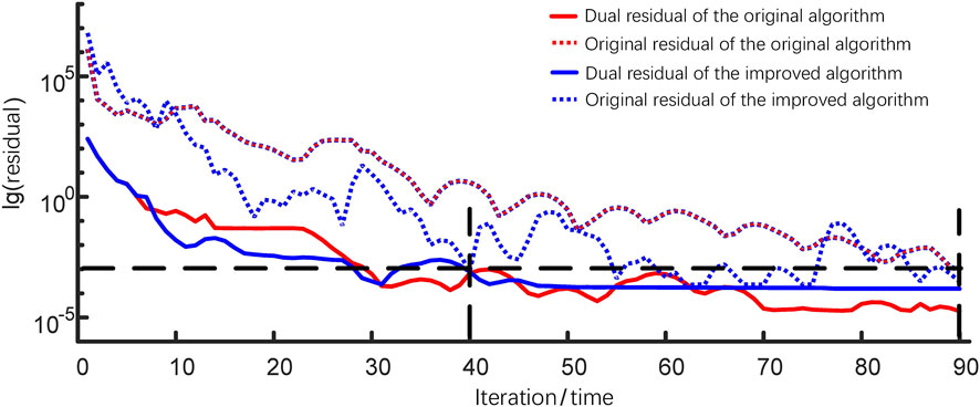
By comparing the convergence performance of the improved algorithm proposed in this article with that of the C-ADMM, the improved algorithm meets the accuracy requirement after 40 iterations. In comparison, the original algorithm needs 90 iterations under the same parameters as shown in Figure 12. In this article, the unit internal optimization and the information interaction between the units with the cloud are integrated and simulated on a computer. According to the simulation statistics, the C-ADMM algorithm takes 79.71 s, while the improved C-ADMM algorithm takes 40.76 s. Therefore, the convergence performance of the improved algorithm is better than that of the original algorithm.
The rationality of the distributed optimization with the ECU as a subsystem was verified by the improved algorithm. At the same time, the improved algorithm is proven to be superior to the original algorithm. The ECU provides a standard unit form for the improved consensus-ADMM algorithm, and their strengths are closely combined to achieve good optimization results.
6 Conclusion and Prospects
From the perspective of the data interaction architecture, this study compares the differences, advantages, and disadvantages of the centralized optimization and distributed optimization, where the IES is decoupled according to the energy networks and the distributed optimization based on the proposed ECU framework. In addition, a unified network partition method is proposed, and the ECU model is introduced in detail.
This study improved the C-ADMM method to adapt to the ECU model. A study case verifies the improved convergence performance of the improved algorithm, and the algorithm was proven to assist the ECU model in completing the distributed optimization of the MRIES well.
In conclusion, the ECU model proposed in this article can fully play the advantages of energy utilization and data management of the RIES and serve as a distributed unit connected to the upper energy network and the lower load layer. Moreover, it breaks through the limitation that the IES distributed optimization with EH as the main body failed to consider the constraints of networks. In addition, the ECU framework can be used as the unit of the MRIES for further research, such as model predictive control and study for the uncertainty involved by wind power and photovoltaic. In addition, the future work will consider carbon emission inthe optimization objective for the carbon peak and carbon neutrality targets.
Data Availability Statement
The raw data supporting the conclusions of this article will be made available by the authors, without undue reservation.
Author Contributions
MW: conceptualization, methodology, software, validation, formal analysis, investigation, writing—original draft, visualization, and resources. HZ: methodology, software, validation, writing—review and editing, supervision, project administration, and funding acquisition. HT: methodology, writing—review and editing, and project administration. QW: methodology, validation, writing—review and editing, and project administration.
Funding
This work was supported by the National Key R&D Program of China under Grant No. 2018YFA0702200.
Conflict of Interest
The authors declare that the research was conducted in the absence of any commercial or financial relationships that could be construed as a potential conflict of interest.
Publisher’s Note
All claims expressed in this article are solely those of the authors and do not necessarily represent those of their affiliated organizations, or those of the publisher, the editors and the reviewers. Any product that may be evaluated in this article, or claim that may be made by its manufacturer, is not guaranteed or endorsed by the publisher.
References
Albataineh, H., Nijim, M., and Bollampall, D. (2020). “The Design of a Novel Smart home Control System Using Smart Grid Based on Edge and Cloud Computing,” in 2020 IEEE 8th International Conference on Smart Energy Grid Engineering (SEGE), 88–91. doi:10.1109/SEGE49949.2020.9181961
Baran, M. E., and Wu, F. F. (1989). Network Reconfiguration in Distribution Systems for Loss Reduction and Load Balancing. IEEE Trans. Power Deliv. 4, 1401–1407. doi:10.1109/61.25627
Cao, K., Zhou, J., Xu, G., Wei, T., and Hu, S. (2019). “Exploring Renewable-Adaptive Computation Offloading for Hierarchical Qos Optimization in Fog Computing,” in IEEE Transactions on Computer-Aided Design of Integrated Circuits and Systems, 1. doi:10.1109/TCAD.2019.2957374
Chen, F., Deng, H., and Shao, Z. (2020). “Distributed Robust Synergistic Scheduling of Electricity, Natural Gas, Heating and Cooling Systems via Admm,” in International Journal of Energy Research. doi:10.1002/er.6379
Chen, J., Zhang, W., Lin, D., Zhihao, L. I., Song, G., and Yifeng, G. U. (2019). “Distributed Optimal Dispatch of Integrated Electricity-Gas-Heating System Based on Improved Alternative Direction Multiplier Method,” in Automation of Electric Power Systems. doi:10.7500/AEPS20180720004
Chen, Q., Xia, M., Chen, M., and Hu, H. (2018). “Distributed Energy Management for Integrated Energy System Considering Multiple Independent Operators,” in 2018 IEEE Power Energy Society General Meeting (PESGM), 1–5. doi:10.1109/pesgm.2018.8586052
Chen, S., Bai, Y., Zhang, Y., Liu, X., Zhang, J., Gao, T., et al. (2019). “A Framework of Decentralized Electricity Market Based on the Collaborative Mechanism of Blockchain and Edge Computing,” in 2019 IEEE International Conference on Service Operations and Logistics, and Informatics (SOLI), 219–223. doi:10.1109/SOLI48380.2019.8955023
Chen, W., Mu, Y., Hongjie, J., Wei, W., and Wei, H. (2021). “Operation Optimization Method for Regional Integrated Energy System that Considers Part-Load Performances of Devices,” in Power System Technology. doi:10.13335/j.1000-3673.pst.2020.1149
Haitao, H., Zha, J., Xi, C., and Jian, L. (2021). Research on Distributed Cooperative Optimization of Multi-Agent Integrated Energy System Based on Admm Algorithm. Harbin, Heilongjiang Province: Electrical Measurement & Instrumentation, 1–9. Available at: http://kns.cnki.net/kcms/detail/23.1202.TH.20210506.1312.006.html (Accessed April 10, 2022).
Haozhong, C., Xiao, H., Li, W., Yuquan, L., and Qi, Y. (2019). “Review on Research of Regional Integrated Energy System Planning,” in Automation of Electric Power Systems, 43, 12. doi:10.7500/AEPS20180416006
Hu, X., Shang, C., Cheng, H., Wang, L., Chen, D., and Yong, L. (2020). “Review and prospect of Calculation Method for Energy Flow in Integrated Energy System,” in Automation of Electric Power Systems, 44, 13. doi:10.7500/AEPS20191113001
Huang, W., Zhang, N., Wang, Y., Capuder, T., and Kang, C. (2019). “Matrix Modeling of Energy Hub with Variable Energy Efficiencies,” in International Journal of Electrical Power and Energy Systems. doi:10.1016/j.ijepes.2020.105876
Liu, D., Zeng, X., and Wang, Y. (2021). “Control Strategy of Virtual Power Station in Distribution Transformer Area under Edge Computing Architecture,” in Transactions of China Electrotechnical Society, 52–56. doi:10.19595/j.cnki.1000-6753.tces.l90517
Liu, T., Zhang, D., and Wu, T. (2020). Standardised Modelling and Optimisation of a System of Interconnected Energy Hubs Considering Multiple Energies-Electricity, Gas, Heating, and Cooling. Energ. Convers. Manage. 205, 112410. doi:10.1016/j.enconman.2019.112410
Ma, M., Fan, L., and Miao, Z. (2016). “Consensus Admm and Proximal Admm for Economic Dispatch and Ac Opf with Socp Relaxation,” in North American Power Symposium. doi:10.1109/naps.2016.7747961
Na, L., Xichao, Z., Bing, W., Lin, C., Tai, J., and Chongchao, P. (2020). “Research on Optimization Models of Integrated Energy System,” in Shanghai Energy Conservation, 6. doi:10.13770/j.cnki.issn2095-705x.2020.06.007
Wang, J., Gu, W., Lu, S., and Zhang, C. (2016). “Coordinated Planning of Multi-District Integrated Energy System Combining Heating Network Model,” in Automation of Electric Power Systems, 40, 8. doi:10.7500/AEPS20160426010
Wang, X., Hong, M., Ma, S., and Luo, Z. Q. (2013). “Solving Multiple-Block Separable Convex Minimization Problems Using Two-Block Alternating Direction Method of Multipliers,” in Pacific Journal of Optimization, 11. doi:10.48550/arXiv.1308.5294
Wang, Y., Zhang, N., Kang, C., Kirschen, D. S., Yang, J., and Xia, Q. (2017). “Standardized Matrix Modeling of Multiple Energy Systems,” in IEEE Transactions on Smart Grid. doi:10.1109/TSG.2017.2737662
Wei, G., Lu, S., Wang, J., Yin, X., and Wang, Z. (2017). “Modeling of the Heating Network for Multi-District Integrated Energy System and its Operation Optimization,” in Proceedings of the Chinese Society of Electrical Engineering, 3737. doi:10.13334/j.0258-8013.pcsee.160991
Weisong, S., Hui, S., Jie, C., Zhang, Q., and Liu, W. (2017). Edge Computing–An Emerging Computing Model for the Internet of Everything Era. Comput. Res. Develop. 54, 18. doi:10.7544/issn1000-1239.2017.20160941
Wen, Y., Qu, X., Li, W., Liu, X., and Ye, X. (2017). “Synergistic Operation of Electricity and Natural Gas Networks via Admm,” in IEEE Transactions on Smart Grid, 1. doi:10.1109/TSG.2017.2663380
Wu, M., Wan, C., Wang, L., Wang, K., and Jiang, Y. (2020). “Hierarchical Autonomous Cooperative Operation of District Integrated Heating and Power System,” in 2020 IEEE/IAS Industrial and Commercial Power System Asia (I&CPS Asia). doi:10.1109/icpsasia48933.2020.9208372
Xu, D., Wu, Q., Zhou, B., Li, C., and Huang, S. (2019). “Distributed Multi-Energy Operation of Coupled Electricity, Heating and Natural Gas Networks,” in IEEE Transactions on Sustainable Energy, 1. doi:10.1109/TSTE.2019.2961432
Yunzhou, Z., Hongcai, D., Xiaoyu, W., Rui, C., and Ning, Z. (2021). Development Trends and Key Issue of china’s Integrated Energy Services. Electric Power 2, 1–10. doi:10.11930/j.issn.1004-9649.202012040
Zhang, X., Yu, T., Zhang, Z., and Tang, J. (2018). Multi-agent Bargaining Learning for Distributed Energy Hub Economic Dispatch. IEEE Access 6, 39564–39573. doi:10.1109/access.2018.2853263
Nomenclature
Abbreviations
ADMM Alternating direction multiplier method
C-ADMM Consensus-alternating direction multiplier method
CHP Combined heat and power
DHN District Heating Network
ECU Edge computing unit
EC Electrical chiller
EHR Electricity consumption to transferred heating quantity ratio
EH Energy hub
GB Gas boiler
GS-ADMM Gauss–Seidel alternating direction multiplier method
HP Heat pump
HS Heat storage
IES Integrated energy system
MILP Mixed-integer linear programming
MISOCP Mixed-integer second-order cone programming
MRIES Multiregion integrated energy system
NC-ADMM Nonconvex alternating direction multiplier method
RIES Regional integrated energy system
SOCP Second-order core programing
Indices
a, b, ω Index of natural gas network nodes
d Index of loads in energy networks
g, pv, wt Indices of electrical generating units, photovoltaic power plants, and wind turbines
i, j, o Index of electrical network nodes
k Index of iteration numbers
p Index of heating network pipelines
r, f Indices of unpartitioned nodes and EH nodes in energy networks
s Index of binary variables
t Index of time intervals
u, v, m Index of heating network nodes
Parameters
μ Proportionality constant
ρ Penalty factor in the C-ADMM algorithm
∑R Total thermal resistance between the heat medium and surrounding medium per kilometer of pipe
θ Penalty factor in the subalgorithm
ce,t, cg,t Electricity price and natural gas price at t
Kab Weymouth characteristic parameter of the pipeline ab
luv Length of the pipe uv
N Number of EHs
pi Circular constant
S Number of binary variables
W Number of pipes in the DHN
Sets
γ ∈ Γ Set of segments in piecewise linearization
Λ(b), Υ(b) Set of loads and downstream nodes connected to node j in the natural gas network
Φ(u) Set of downstream nodes connected to node u in the DHN
Π(j), Ω(j) Set of devices and downstream nodes connected to node j in the power system
Θn Set of energy transmission lines between the nth ECU with others
Variables
σγ, ηγ Value of the γ-th segment of X and coefficient of the γ-th segment of FL(X)
EHRp The EHR of the water pump p
CB, zB,B Continuous variable, auxiliary variable, and binary variable,CB ∈ [0, 1]
HEH Heating input of EH from the DHN
Hav Available heating
Hp,t Heating transferred in pipe p
Lcool, Lelec, Lheat Cooling, electricity, and heating loads of the EH
PEH, GEH Power and natural gas input of the EH
q Mass flow
quv,t, qvu,t Mass flow from node u to node v and node v to node u at t
Rij, Xij Resistance and reactance of branch ij
T, Te Real temperature and ambient temperature
Trw, Tsw Return water temperature and supply water temperature
Tuv,t, Tvu,t Temperature of heat medium from node u to node v and node v to node u at t
V Matrix of coupling equipment’s input and output energy
V1 Matrix of the EH’s input resources and loads
X, X0 Continuous variable and its initial value
xαβ,α,t, xαβ,β,t Coupling variables on both sides of the virtual node at t
yrf Binary variable of node r partition to region f
Z Standard matrix of the EH
zαβ,t Consensus variable of the virtual node at t
λαβ,α,t, λαβ,β,t Lagrange multipliers of the ECUs on both sides of the virtual node at t
Keywords: edge computing unit, multiregional integrated energy system, distributed collaborative optimization, energy hub, energy conservation
Citation: Wang M, Zhao H, Tian H and Wu Q (2022) Distributed Collaborative Optimization of a Multi-Region Integrated Energy System Based on Edge Computing Unit. Front. Energy Res. 10:846006. doi: 10.3389/fenrg.2022.846006
Received: 30 December 2021; Accepted: 1 April 2022;
Published: 26 April 2022.
Edited by:
Athanasios I. Papadopoulos, Centre for Research and Technology Hellas (CERTH), GreeceEdited by:
Athanasios I. Papadopoulos, Centre for Research and Technology Hellas (CERTH), GreeceReviewed by:
Yue Xia, China Agricultural University, ChinaHua Ye, Chinese Academy of Sciences (CAS), China
Copyright © 2022 Wang, Zhao, Tian and Wu. This is an open-access article distributed under the terms of the Creative Commons Attribution License (CC BY). The use, distribution or reproduction in other forums is permitted, provided the original author(s) and the copyright owner(s) are credited and that the original publication in this journal is cited, in accordance with accepted academic practice. No use, distribution or reproduction is permitted which does not comply with these terms.
*Correspondence: Haoran Zhao, aHpoYW9AbWFpbC5zZHUuZWR1LmNu
 Mengxue Wang
 Haoran Zhao1*
 Hang Tian
 Qiuwei Wu