- School of Computer Engineering, Nanjing Institute of Technology, Nanjing, China
In order to solve the problems of large reflux and low output performance of the valveless piezoelectric pump with conical tubes, the valveless piezoelectric pump with hyperbolic tubes was proposed. However, the previous research only paid attention to the difference of forward and reverse flow resistance inside the tubes. For this reason, the prototypes of conical tube valveless piezoelectric pump and hyperbolic tubes valveless piezoelectric pump were fabricated in this paper. The maximum output flow rate of the valveless piezoelectric pump with hyperbolic tubes was 54 ml/min. Subsequently, the size and position of entropy production of the hyperbolic tube and the conical tube were numerically calculated based on entropy production theory in this paper. The results show that the entropy production rate of the hyperbolic tube was significantly lower than that of the conical tube, which is consistent with the experimental results. This research analyzed the energy loss inside the valveless piezoelectric pump by using the entropy generation theory, and provided a new design and research method for improving the output performance of the valveless piezoelectric pump in the future.
Introduction
As the core component of the micro-fluid control system, the output performance of the micro pump determines the characteristics of the entire system. According to different driving methods, micro pumps can be divided into electromagnetic pumps (Mi et al., 2020; Rusli et al., 2018) heat pumps (Feng et al., 2021; Skye and Wu, 2021), pneumatic pumps (Hamid et al., 2017; Ma et al., 2019), shape memory pumps (Robertson et al., 2016) and piezoelectric pumps (Huang et al., 2020; Ma et al., 2016; Ma et al., 2015). Among them, piezoelectric pumps have attracted more and more attention for their outstanding advantages such as high energy density, fast response speed, large driving force, and easy integration. According to whether there are valves inside, piezoelectric pumps can be divided into valve piezoelectric pumps and valveless piezoelectric pumps (Singhal et al., 2004; Li et al., 2021). The valve piezoelectric pump has a movable valve, which can avoid backflow and generate a larger output pressure. However, due to the existence of micro-valves, processing and assembly are difficult. In addition, the valve is easy to wear and there is a risk of fatigue damage, which greatly reduces the reliability of the valve piezoelectric pump. Compared with the former, the valveless piezoelectric pump uses a fluid diode to replace the active valve, which simplifies the structure of the valveless piezoelectric pump, makes it easy to miniaturize, and improves the system integration (Zhang et al., 2017).
The valveless piezoelectric micropump is usually composed of a piezoelectric vibrator, a pump body and a fluid diode. The fluid diode has the characteristics of unequal flow resistance between the forward and reverse directions, so it is the most important part of the valveless pump. Among them, the cone tube, as the most classic fluid diode, was first used in valveless piezoelectric pumps (Stemme and Stemme, 1993; Olsson et al., 1997). Because there is no movable valve, there are shortcomings of large output return and low output performance for the valveless piezoelectric pump. To this end, many researchers have proposed valveless piezoelectric pumps such as Tesla tube (Morris and Forster, 2003; Gamboa et al., 2005), Y-shaped tube (Zhang et al., 2008), multi-stage bifurcated tube0 (Fadl et al., 2010; Huang et al., 2014), spiral tube (Leng et al., 2013), and vortex tube (Huang et al., 2019; Huang et al., 2021) to reduce backflow and increase output flow.
However, the conical tubes valveless piezoelectric pump is still widely studied due to its simple structure. Among them, Zhang et al. (Bian et al., 2020) proposed the hyperbolic tubes valveless piezoelectric pump based on the conical tube, aiming to improve the output performance of the valveless piezoelectric pump by reducing the vortex during the flow of the piezoelectric pump. However, this study only used software simulation (Tang et al., 2021) and combined with experimental research on the internal flow field distribution of the hyperbolic tubes to illustrate the flow characteristics of the pump (Wang et al., 2020). Therefore, this article will analyze minutely the internal flow and energy loss of the hyperbolic tubes valveless piezoelectric pump based on the entropy generation theory. Subsequently, the size and position of entropy generation in the conical tube and the hyperbolic tube are obtained by numerical calculation. Finally, the output performance experiments of the prototypes are carried out. The calculation and analysis of fluid diodes using entropy generation theory can provide new ideas for improving the output performance of valveless piezoelectric pumps.
Structural Design and Working Principle
Design of Hyperbolic Tube
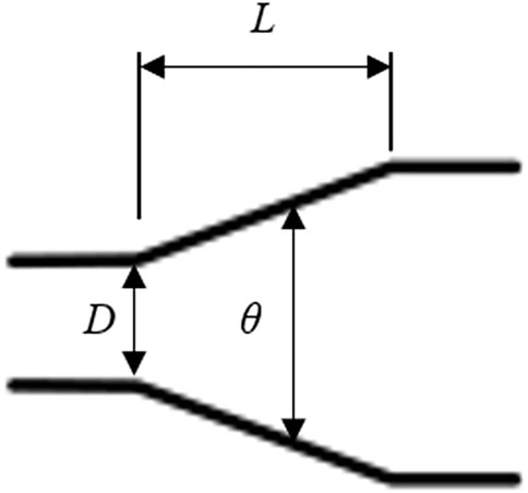
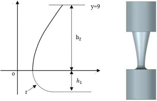
Figure 1 shows a schematic diagram of the conical tube structure, in which L is the length of the conical tube, D is the diameter of the throat of the conical tube, and θ is the cone angle. The hyperbolic tube is made by changing the structure of the conical tube, that is, the gradually expanding straight wall of the conical tube is changed to a hyperbolic wall, and the throat of the conical tube is changed to a circular arc transition section. The left side of Figure 2 shows the wall curve of the hyperbolic tubes, where h1 is the height of the arc section, h2 is the height of the hyperbola section, and r is the minimum radius of the flow channel of the tube. The hyperbolic function is:
Among them, a is equal to r, and b is the only variable in Formula (1). Constrain the hyperbola with two straight lines y = 0 and y = 9. The arc part at the throat is constructed by Formula (2):
Finally, the obtained hyperbolic arc streamline is rotated 360° around the axis to obtain the inner flow passage of the hyperbolic tube as shown in the right side of Figure 2.
Working Principle
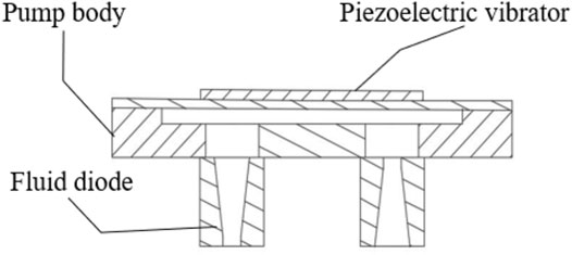
The valveless piezoelectric pump with hyperbolic tubes is composed of a piezoelectric vibrator, a pump body containing two hyperbolic tubes, and a pump cover, as shown in Figure 3. In this study, the fluid flowing from the arc section into the hyperbola is defined as the forward flow, and the fluid flowing from the hyperbolic section into the arc section is defined as the reverse flow. The piezoelectric vibrator receives the current voltage signal to generate up and down vibrations to change the volume of the pump cavity and change the pressure inside the pump cavity, so as to realize the unidirectional transportation of the fluid on the macroscopic level.
The circular piezoelectric vibrator is fixed by adhering its periphery to the pump body, and AC voltage is applied to generate periodic vibration, and its vibration shape is approximately parabolic. By establishing a polar coordinate system, the origin of the coordinate system is the center of the piezoelectric vibrator, then the polar coordinate equation of the parabola:
In the formula, Ω0is the maximum amplitude, R is the radius of the piezoelectric vibrator, and the maximum volume change of the pump cavity is:
The flow resistance experienced by the fluid in the hyperbolic tube is mainly local resistance and friction resistance, as shown below:
In the formula, γ+ is the total forward flow resistance coefficient of the hyperbolic tube, and γ− is the total reverse flow resistance coefficient of the tube. The output flow of the pump can be expressed as:
Where ƒ is the driving frequency of the piezoelectric vibrator.
Experimental Setup
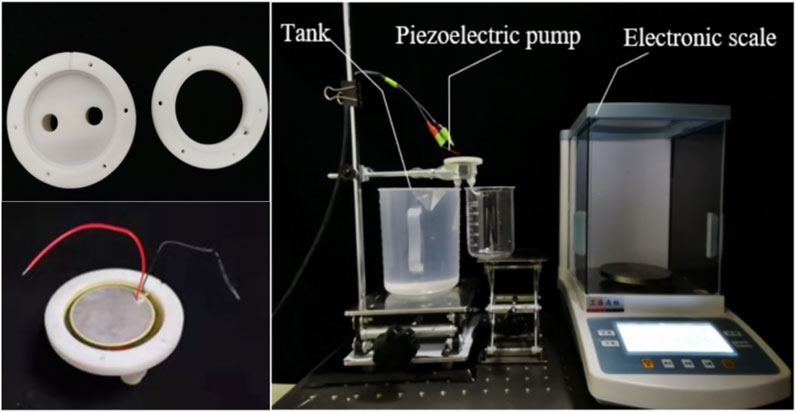
In this paper, a stereolithography machine (SLA) was used to fabricate the valveless piezoelectric pump with conical tubes and the valveless piezoelectric pump with hyperbolic tubes. As shown in the left of Figure 4, the pump body is made of photosensitive resin. The tube parameters are shown in Table 1, the pump cavity diameter is 41 mm, the pump cavity depth is 0.8 mm, and the vibrator radius is 41 mm.
The experimental setup of the piezoelectric pumps with two tubes is shown in the right of Figure 4. The input AC voltage of the piezoelectric pump is set to 200 Vpp (peak-to-peak voltage). The reservoir contained a certain amount of deionized water. Take the small radius of the flow tube as the inlet and the flow tube with joints as the outlet, and the liquid level of the inlet and outlet are the same during the experiment. The analytical balance is used to measure the output flow of the piezoelectric pump per unit time under different frequencies. The accuracy of the analytical balance is 0.001 g.
Simulation Analysis
Entropy Generation Theory
During the operation of the valveless piezoelectric pump, due to the viscosity of the working fluid and Reynolds stress, the consumed mechanical energy is irreversibly converted into internal energy. According to the second law of thermodynamics, the entropy generation theory is used to calculate the energy loss.
For turbulent flow, based on the Reynolds time-average equation, the entropy generation rate can be divided into two parts, the one is caused by the average velocity, called the direct dissipation term; the other is caused by the pulsating velocity, called the turbulent dissipation term. So, define the local total entropy production rate SD per unit volume as:
In the formula,
The entropy production rate caused by the average speed is:
The entropy production rate caused by the pulsating velocity is
Where
However, the pulsating velocity component cannot be calculated in the Reynolds average equation. This paper adopts the k-epsilon turbulence (Shi et al., 2020; Han et al., 2021) model. Therefore, the entropy generation rate produced by the pulsating velocity can be approximated by the following formula.
In the formula, the empirical coefficient β = 0.09, ƒ is the characteristic frequency of turbulent pulsation, s−1, k is turbulent kinetic energy, m2/s2; ρ is the density, kg/cm3.
Integrating the above-mentioned parts of the entropy production rate in the integration area, the direct dissipation entropy production
Therefore, the entropy production of the mainstream area in the entire computational domain is:
According to the entropy generation calculation results of the conical tube and the hyperbolic tube, the resistance coefficient ɛ is used to describe the flow performance and defined in Eq. 16. the impedance ratio is defined in Eq. 17, which is adopted to describe the unidirectional transport performance of the tube.
Hyperbolic Tube Grid Establishment
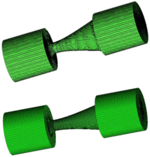
The finite element models of the tubes are shown in Figure 5 (the conical tube on the top and the hyperbolic tube on the bottom). The k-epsilon turbulence model is adopted, because there is small turbulence in tubes. The wall is a non-slip boundary, the pressure applied to the inlet is 500, 1,000, 2,000, and 4,000 Pa, the outlet of the tube is defined as 0 Pa, and the numerical convergence residual is set to 10–4.
The grid independence of the model is verified. Table 1 shows the calculation results of grid independence, where N is the number of grids, Q is the flow rate (kg/s), and r is the relative error. When the mesh numbers of the conical tube and the hyperbolic tube are 375,700 and 279,000 respectively, the error is less than 1%, so the finite element model is used to calculate the entropy generation.
Results and Discussion
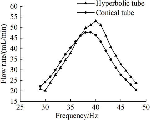
The experimental result of the pump flow rate is shown in Figure 6. The output flow rate of the piezoelectric pump with hyperbolic tubes is finally measured at a frequency of 40 Hz, which is 54 ml/min. The maximum output flow rate of the piezoelectric pump with conical tube is 47 ml/min. Therefore, the output performance of the piezoelectric pump with hyperbolic tubes is greater than that of the piezoelectric pump with conical tubes.
Calculate the viscous entropy production and turbulent entropy production under different pressure differences when the two tubes are flowing in the forward direction, as shown in Table 2 and Table 3. It can be seen that under the same working conditions, the turbulent entropy production and viscous entropy production of the hyperbolic tube are smaller than that of the conical tube. Therefore, the output performance of the piezoelectric pump with hyperbolic tubes is better than that of the piezoelectric pump with conical tubes.
The difference between the forward and reverse flow resistance of the hyperbolic tube directly affects the cut-off performance, which in turn affects the output performance of the valveless piezoelectric pump with hyperbolic tubes.
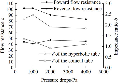
Figure 7 shows that the forward flow resistance of the hyperbolic tube is smaller than the reverse flow resistance, indicating that unidirectional transport of fluid can be achieved. Moreover, the impedance ratio of the hyperbolic tube is larger than that of the conical tube, indicating that the unidirectional transport performance of the hyperbolic tube is better than that of the conical tube.
Figure 8A shows the turbulent entropy production of the conical tube. The turbulent entropy production is mainly caused by turbulent dissipation. It can be seen that the turbulent entropy production is symmetrically distributed on the axis of the conical tube, and it is greater in the reverse flow than that in the forward flow. Figure 8B shows the viscous entropy production of the conical tube. Compared with the turbulent entropy production, the viscous entropy production is smaller. The viscous entropy production is mainly caused by the dissipation of the irreversible viscous entropy production. The viscous entropy production is at the smallest radius of the tube. The maximum, decreases as the tube spreads.
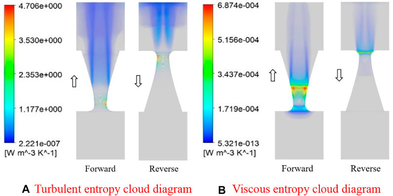
FIGURE 8. Entropy cloud diagram of the conical tube. (A) Turbulent entropy cloud diagram (B) Viscous entropy cloud diagram.
Figure 9A shows the viscous entropy production of the hyperbolic tube. Compared with the conical tube, the viscous entropy production area of the hyperbolic tube in the forward and reverse flow is smaller than that of the conical tube. Figure 9B shows the turbulent entropy production of the hyperbolic tube. Compared with the conical tube, the turbulent entropy production of the hyperbolic tube is much smaller than that of the conical tube, and the viscous entropy production is less dissipated. In summary, the entropy production at the smallest channel diameter of the tube is larger, and both viscous entropy production and turbulent entropy production are positively correlated with the pressure difference, but the turbulent entropy production and viscous entropy production of the hyperbolic tube are both smaller than those of the conical tube.
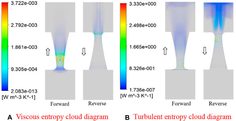
FIGURE 9. Entropy cloud diagram of the hyperbolic tube. (A) Viscous entropy cloud diagram (B) Turbulent entropy cloud diagram.
Figure 10A and Figure 11Arespectively show the velocity cloud diagrams of the conical tube and the hyperbolic tube. It can be seen that the flow velocity of the fluid in the hyperbolic tube is greater than that in the conical tube. In addition, there is a larger vortex in the conical tube, which is larger than the hyperbolic tube, which has a greater impact on the flow of fluid in the tube. Figure 10B and Figure 11B respectively show the pressure cloud diagrams of the conical tube and the hyperbolic tube. It can be seen that the reverse cut-off performance of the hyperbolic tube is better than that of the conical tube.
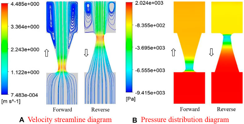
FIGURE 10. Flow distribution simulation results of the conical tube. (A) Velocity streamline diagram (B) Pressure distribution diagram.
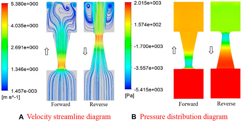
FIGURE 11. Flow distribution simulation results of the hyperbolic tube. (A) Velocity streamline diagram (B) Pressure distribution diagram.
Therefore, under the same working conditions, the energy loss of the hyperbolic tube is smaller than that of the conical tube, and the output performance of the hyperbolic tube piezoelectric pump is better than that of the conical tube piezoelectric pump.
Conclusion
In order to improve the flow characteristics of the valveless piezoelectric pump, two valveless piezoelectric pumps with tubes with different curves as the inlet and outlet pipes were developed. The prototypes of the piezoelectric pumps were fabricated, and the experimental results showed that the hyperbolic tubes had the largest flow rate, and the corresponding valveless piezoelectric pump had better output performance. The entropy generation theory was used to analyze the energy loss of the tube, and the entropy production values of the tubes were calculated. The results show that the total entropy produced by the hyperbolic curve tube is smaller than the entropy produced by the conical tube. The entropy generation theory can effectively predict and analyze the energy loss of the tubes, and provide a reference for the structural design and performance optimization of the piezoelectric pump.
Data Availability Statement
The datasets presented in this study can be found in online repositories. The names of the repository/repositories and accession number(s) can be found in the article/supplementary material.
Author Contributions
QY and JC contributed to conception and design of the study. QY and JC performed the simulation analysis. QY wrote the first draft of the manuscript. JC wrote sections of the manuscript. All authors contributed to manuscript revision, read, and approved the submitted version.
Conflict of Interest
The authors declare that the research was conducted in the absence of any commercial or financial relationships that could be construed as a potential conflict of interest.
Publisher’s Note
All claims expressed in this article are solely those of the authors and do not necessarily represent those of their affiliated organizations, or those of the publisher, the editors and the reviewers. Any product that may be evaluated in this article, or claim that may be made by its manufacturer, is not guaranteed or endorsed by the publisher.
References
Bian, K., Huang, Z., Bao, Q. B., Zhang, J. H., Lai, L., Chen, X. S., et al. (2020). Design and experiment of Streamlined Piezoelectric Pump with Low Vortex and Large Flow Rate. Trans. Nanjing Univ. Aeronautics Astronautics 37 (01), 155–163. doi:10.16356/j.1005-1120.2020.01.014
Fadl, A., Demming, S., Zhang, Z., Büttgenbach, S., Krafczyk, M., and Meyer, D. M. L. (2010). A Multifunction and Bidirectional Valve-Less Rectification Micropump Based on Bifurcation Geometry. Microfluid Nanofluid 9, 267–280. doi:10.1007/s10404-009-0544-0
Feng, L., Jin, Z., Zhou, R., Xu, M., Qin, L., and Li, S. (2021). Thermodynamic Analysis of an Ammonia-Water Solution Cross-type Absorption-Resorption Heat Pump System. Appl. Therm. Eng. 198, 117460. doi:10.1016/j.applthermaleng.2021.117460
Gamboa, A. R., Morris, C. J., and Forster, F. K. (2005). Improvements in Fixed-Valve Micropump Performance through Shape Optimization of Valves. J. Fluids Eng. 127, 339–346. doi:10.1115/1.1891151
Hamid, N. A., Majlis, B. Y., Yunas, J., Syafeeza, A. R., Wong, Y. C., and Ibrahim, M. (2017). A Stack Bonded Thermo-Pneumatic Micro-pump Utilizing Polyimide Based Actuator Membrane for Biomedical Applications. Microsyst Technol. 23, 4037–4043. doi:10.1007/s00542-016-2951-y
Han, Y., Zhou, L., Bai, L., Shi, W., and Agarwal, R. (2021). Comparison and Validation of Various Turbulence Models for U-bend Flow with a Magnetic Resonance Velocimetry experiment. Phys. Fluids 33, 125117. doi:10.1063/5.0073910
Huang, J., Li, K., Chen, G., Gong, J., Zhang, Q., and Wang, Y. (2021). Design and Experimental Verification of Variable-Structure Vortex Tubes for Valveless Piezoelectric Pump Translating High-Viscosity Liquid Based on the Entropy Generation. Sensors Actuators A: Phys. 331, 112973. doi:10.1016/j.sna.2021.112973
Huang, J., Zhang, J., Wang, S., and Liu, W. (2014). Analysis of the Flow Rate Characteristics of Valveless Piezoelectric Pump with Fractal-like Y-Shape Branching Tubes. Chin. J. Mech. Eng. 27, 628–634. doi:10.3901/cjme.2014.03.628
Huang, J., Zou, L., Li, Z., Wang, X., Zhang, Q., and Wang, Y. (2020). Development and Performance Comparison of Valveless Piezoelectric Pumps with Asymmetrical Channels. Sensors Actuators A: Phys. 314, 112241. doi:10.1016/j.sna.2020.112241
Huang, J., Zou, L., Tian, P., Wang, Y., and Zhang, Q. (2019). Development of a Valveless Piezoelectric Pump with Vortex Diodes. J. Micromech. Microeng. 29 (12), 125006. doi:10.1088/1361-6439/ab4852
Leng, X.-f., Zhang, J.-h., Jiang, Y., Zhang, J.-Y., Sun, X.-c., and Lin, X.-g. (2013). Theory and Experimental Verification of Spiral Flow Tube-type Valveless Piezoelectric Pump with Gyroscopic Effect. Sensors Actuators A: Phys. 195, 1–6. doi:10.1016/j.sna.2013.02.026
Li, H., Liu, J., Li, K., and Liu, Y. (2021). A Review of Recent Studies on Piezoelectric Pumps and Their Applications. Mech. Syst. Signal Process. 151, 107393. doi:10.1016/j.ymssp.2020.107393
Ma, H.-K., Luo, W.-F., and Lin, J.-Y. (2015). Development of a Piezoelectric Micropump with Novel Separable Design for Medical Applications. Sensors Actuators A: Phys. 236, 57–66. doi:10.1016/j.sna.2015.10.010
Ma, H. K., Chen, R. H., Yu, N. S., and Hsu, Y. H. (2016). A Miniature Circular Pump with a Piezoelectric Bimorph and a Disposable Chamber for Biomedical Applications. Sensors Actuators A: Phys. 251, 108–118. doi:10.1016/j.sna.2016.10.010
Ma, T., Sun, S., Li, B., and Chu, J. (2019). Piezoelectric Peristaltic Micropump Integrated on a Microfluidic Chip. Sensors Actuators A: Phys. 292, 90–96. doi:10.1016/j.sna.2019.04.005
Mi, S., Pu, H., Xia, S., and Sun, W. (2020). A Minimized Valveless Electromagnetic Micropump for Microfluidic Actuation on Organ Chips. Sensors Actuators A: Phys. 301, 111704. doi:10.1016/j.sna.2019.111704
Morris, C. J., and Forster, F. K. (2003). Low-order Modeling of Resonance for Fixed-Valve Micropumps Based on First Principles. J. Microelectromech. Syst. 12, 325–334. doi:10.1109/jmems.2003.809965
Olsson, A., Enoksson, P., Stemme, G., and Stemme, E. (1997). Micromachined Flat-Walled Valveless Diffuser Pumps. J. Microelectromech. Syst. 6, 161–166. doi:10.1109/84.585794
Robertson, J. M., Rodriguez, R. X., Holmes, L. R., Mather, P. T., and Wetzel, E. D. (2016). Thermally Driven Microfluidic Pumping via Reversible Shape Memory Polymers. Smart Mater. Struct. 25 (8), 085043. doi:10.1088/0964-1726/25/8/085043
Rusli, M., Chee, P. S., Arsat, R., Lau, K. X., and Leow, P. L. (2018). Electromagnetic Actuation Dual-Chamber Bidirectional Flow Micropump. Sensors Actuators A: Phys. 282, 17–27. doi:10.1016/j.sna.2018.08.047
Shi, L., Zhu, J., Tang, F., and Wang, C. (2020). Multi-Disciplinary Optimization Design of Axial-Flow Pump Impellers Based on the Approximation Model. Energies 13 (4), 779. doi:10.3390/en13040779
Singhal, V., Garimella, S. V., and Raman, A. (20042004). Microscale Pumping Technologies for Microchannel Cooling Systems. Appl. Mech. Rev. 57 (1), 191. doi:10.1115/1.1695401
Skye, H. M., and Wu, W. (2021). Experiments and Exergy Analysis for a Carbon Dioxide Ground-Source Heat Pump in Cooling Mode. Int. J. Refrigeration 131, 920–937. doi:10.1016/j.ijrefrig.2021.08.018
Stemme, E., and Stemme, G. (1993). A Valveless Diffuser/nozzle-Based Fluid Pump. Sensors Actuators A: Phys. 39, 159–167. doi:10.1016/0924-4247(93)80213-z
Tang, S., Zhu, Y., and Yuan, S. (2021). An Improved Convolutional Neural Network with an Adaptable Learning Rate towards Multi-Signal Fault Diagnosis of Hydraulic Piston Pump. Adv. Eng. Inform. 50, 101406. doi:10.1016/j.aei.2021.101406
Wang, H., Long, B., Wang, C., Han, C., and Li, L. (2020). Effects of the Impeller Blade with a Slot Structure on the Centrifugal Pump Performance. Energies 13 (7), 1628. doi:10.3390/en13071628
Zhang, J.-H., Wang, Y., and Huang, J. (2017). Advances in Valveless Piezoelectric Pump with Cone-Shaped Tubes. Chin. J. Mech. Eng. 30 (4), 766–781. doi:10.1007/s10033-017-0151-z
Keywords: hyperbolic tube, conical tube, valveless piezoelectric pump, entropy generation, output flow
Citation: Yang Q and Chen J (2022) Entropy Analysis of a Valveless Piezoelectric Pump With Hyperbolic Tubes. Front. Energy Res. 10:841730. doi: 10.3389/fenrg.2022.841730
Received: 22 December 2021; Accepted: 12 January 2022;
Published: 14 February 2022.
Edited by:
Ling Zhou, Jiangsu University, ChinaCopyright © 2022 Yang and Chen. This is an open-access article distributed under the terms of the Creative Commons Attribution License (CC BY). The use, distribution or reproduction in other forums is permitted, provided the original author(s) and the copyright owner(s) are credited and that the original publication in this journal is cited, in accordance with accepted academic practice. No use, distribution or reproduction is permitted which does not comply with these terms.
*Correspondence: Jun Chen, Y2hlbmpAbmppdC5lZHUuY24=
 Qing Yang
 Jun Chen