 Xiu Zhou
 Tian Tian
- State Grid Ningxia Electric Power Co Ltd., Electric Power Research Institute, Yinchuan, China
In recent years, the calculation of the core grounding current of the converter transformer is difficult, low precision, and time-consuming, especially when the core is grounded by multiple points. This makes it difficult to analyze the core grounding current. To improve the accuracy of the calculation and reduce the complexity of the calculation, this paper carries out analytical calculation, simulation analysis, and experimental research on the grounding current of the converter transformer core. Firstly, a calculation method of core grounding current considering the winding connection of the converter transformer is proposed. In the implementation process, the converter transformer circuit model is established and the influence of saturation characteristics is considered, and the core grounding current is calculated and analyzed. Secondly, the grounding current of the converter transformer core is calculated by the finite element method (FEM). Finally, the proposed scheme is verified by experiments. The results show that the analytical method is close to the FEM and the experimental method, which indicates that the analytical method proposed can meet the accuracy requirements of engineering in this paper, and provides a new scheme for fast and accurate calculation of the grounding current of the converter transformer core.
Introduction
A converter transformer is one of the important equipment in a UHVDC transmission system. The safety and stability of converter transformer operation are directly related to the stable operation of the power network. Therefore, it is of great significance to carry out the operational status and evaluation of the converter transformer (Dai et al., 2016).
Under the action of electric and magnetic fields inside the converter transformer during operation, the core and other components have different potentials. Assuming that the core is not reliably grounded, the potential of each part of the core is different, which will produce a discharge phenomenon and destroy the insulation. Figure 1 shows the insulation damage of the converter transformer’s pull belt. When the converter transformer core is multi-point grounded, the two ground points form a closed loop through the core and the grounding wire, and a large grounding current will be generated in the loop, resulting in the converter transformer core grounding fault (Hamzehbahmani et al., 2014; Zhang, Zhan, Yi). The ground current of converter transformer is larger, the limit value is 300mA; The grounding current of small transformers is smaller and the limit value is 100 mA.
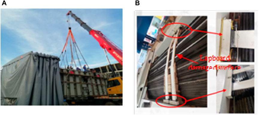
FIGURE 1. Insulation damage of the converter transformer’s pull belt: (A) converter transformer repair site; (B) multi-point grounding of the core.
In (Geng, Wang), the working current of the one-point grounding of the transformer core is calculated, and the model of the one-point grounding current of the transformer core is established. In (Zhou et al., et al.), a transformer model with a multi-point underground connection is established, and the influence of transformer core homogenization is taken into account. In (Zhang et al., et al.), based on the online grounding system of converter transformer core grounding current, the measurement research on converter transformer core grounding current is carried out, and the law of grounding current is summarized. In (Zhang, Su, Zhou, He, Xiao) an experimental study was carried out on the harmonic characteristics of the converter transformer core grounding current, obtained the converter transformer core grounding current and its harmonic characteristics data curves under different transmission powers, and summarized its pattern. In (Wang et al., 2012), Transformer oil was analyzed by meteorological chromatography under grounding fault conditions. In (Ming-Cai et al., 2022), iron core multi-point grounding automatic protection and control system with 10 kV dry-type transformer is designed.
Based on the above analysis, the research on transformer core grounding current is still based on experiments, and the mathematical modeling of transformer core grounding current is lacking. Therefore, in this paper, the core grounding current of the converter transformer is modeled mathematically, the influence of connection mode is considered, and the mathematical expression of the core grounding current of the converter transformer is given. Secondly, through finite element analysis, the finite element simulation model of transformer core grounding current is established, and the simulation research is carried out. Finally, an experimental study on the grounding current of the converter transformer core is carried out, and the analytical method, FEM, and experimental method are compared to verify the correctness of the proposed scheme.
Basic structure and parameters of converter transformer
The converter transformer in the UHVDC transmission system analyzed in this paper is composed of three single-phase power transformers. The main structure of the converter transformer is shown in Figure 2, and the basic parameters of the converter transformer are shown in Table 1.
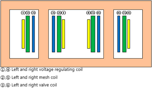
FIGURE 2. Converter transformer main structure.
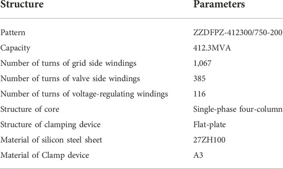
TABLE 1. Basic parameters of converter transformer.
As shown in Figure 2, the core of the converter transformer adopts single-phase four-column structure, and the windings are divided into grid-side windings, valve-side windings, and voltage-regulating windings. The windings on each column are connected in parallel, wherein the grid-side winding is connected to the grid, and the valve-side winding and the voltage-regulating winding are connected to the converter valve.
Core grounding current modeling of converter transformer
Modeling of converter transformer
As shown in Figure 3, the converter transformer mainly includes three parts: high-voltage winding, medium-voltage winding, and low-voltage winding. R1, R2, and R3 are the resistance of high-voltage winding, medium-voltage winding, and low-voltage winding; L1, L2, and L3 are the inductances of high-voltage winding, medium-voltage winding, and low-voltage winding; Lm is the excitation inductance; Lsat is the saturation inductance.
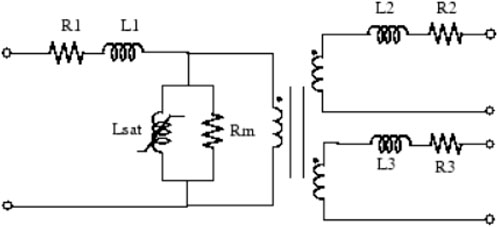
FIGURE 3. Shows the equivalent circuit diagram of the converter transformer.
The voltage equation of the converter transformer is established according to Figure 3, as shown in Eq. 1.
where N1 is the turns of the primary side, N2 is the turns of the secondary side, i1 is the current of the primary side, i2 is the turns of the secondary side, im is the exciting current, Φis the flux linkage, B is the flux density, S is the area, F is the magnetomotive force, H is the magnetic field intensity, L is the magnetic circuit length, N the is the turns, and i is the current.
For further analysis, considering the influence of transformer saturation characteristics, its saturation characteristics are determined by the curves of flux and excitation current, as shown in Figure 4.
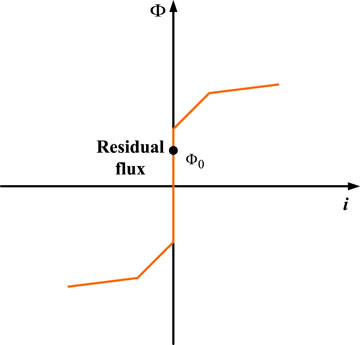
FIGURE 4. Current and flux curve.
Therefore, if
where
According to (1)–(3), when the sinusoidal voltage source is connected to the primary side winding, the voltage of the primary side winding can be obtained, and the expression of magnetic flux can be obtained by integrating this voltage, and the expression of current can be obtained by inputting this expression of magnetic flux into the curve in Figure 4. In this way, the magnetic flux and current equations of other windings can be obtained.
Modeling of core grounding current of converter transformer
Figure 5 shows the two connection modes of a converter transformer in a power system and a prototype converter transformer.
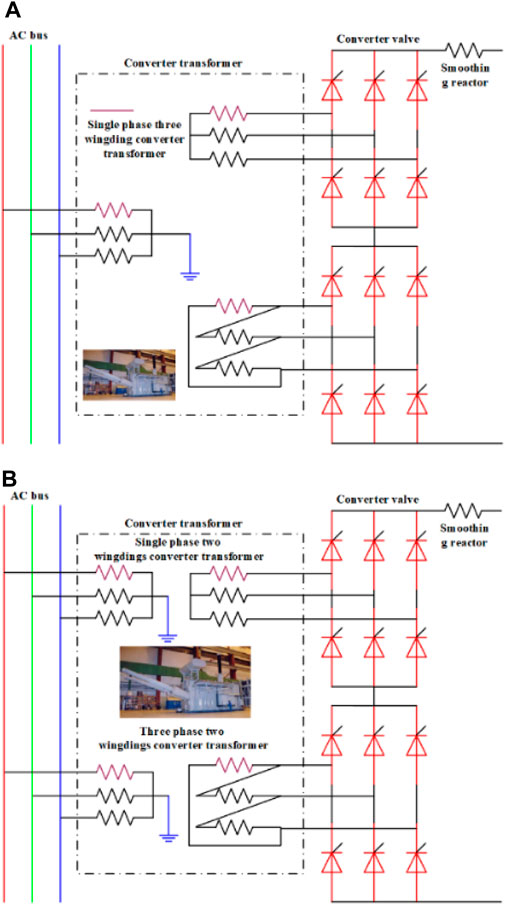
FIGURE 5. Converter transformer main connection mode: (A) Converter transformer adopts single-phase three winding structure; (B) Converter transformer pole I high single-phase double winding structure, pole I low three-phase double winding structure.
There are some similarities in the calculation of ground current between converter transformer and power transformer. To form a unified theory of the grounding current of the power transformer core, the grounding current of the power transformer core with YN/YAI and YNynd11 winding structures is analyzed below. The single-point grounding of YN/YAI and YNynd11 cores is shown in Figure 6.
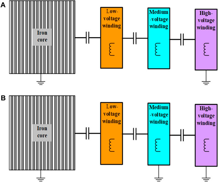
FIGURE 6. Single point grounding diagram of YN/YAI and YNynd11 cores: (A) YN/YAI structure; (B) YNynd11 structure.
For the converter transformer, firstly, to prevent the floating potential discharge, the iron core needs to be grounded; secondly, the grid-side winding (high-voltage winding) of the converter transformer adopts graded insulation and needs to be grounded; at the same time, the valve winding (medium-voltage and low-voltage winding) has DC voltage, and it is a fully insulated structure, so it is not grounded.
Generally, the grounding current of the power transformer core is capacitive. Therefore, the equivalent circuit diagram of the grounding current of the power transformer core shown in Figure 6 can be established through the schematic diagram of the single-point grounding structure of the core shown in Figure 5.
where Rs is the equivalent resistance of insulating film on the surface of the core silicon steel sheet of the power transformer, CC-L is distributed capacitance of core and low-voltage winding, UL is the voltage of low-voltage winding, CL-M has distributed capacitance of the core and medium-voltage winding, UM is the voltage of medium-voltage winding, CM-H has distributed capacitance of core and high-voltage winding, UH is the voltage of the high-voltage winding.
As shown in Figure 6, the loop impedance of the power transformer is the sum of the equivalent impedances between the core and the windings, between the windings and the insulating film on the surface of the core silicon steel sheet. Therefore, as long as the loop impedance value of each part is calculated, the grounding current calculation of the iron core of the power transformer can be completed. The grounding current of the converter transformer core can be written as follows:
where iGA, iGB, and iGC are the core grounding currents of phase A, phase B, and phase C of the converter transformer respectively.
It can be seen from Eqs. 4, 5 that the grounding current of the converter transformer core is related to the coating resistance on the surface of the silicon steel sheet, the three-phase voltage, the equivalent capacitance between the core and the windings, the equivalent capacitance between the windings and the power supply frequency.
Since the coating resistance on the surface of silicon steel sheet, three-phase voltage, and power supply frequency are known conditions, and the equivalent capacitance between the core and the windings, and the equivalent capacitance between the windings are affected by aging, winding deformation, and other factors, the following calculation is carried out.
The internal insulation of the converter transformer is an oil-immersed insulation structure, which adopts oil-paper insulation. Before calculating the capacitance, it is necessary to calculate the equivalent dielectric constant of the composite insulation. The equivalent dielectric constant between windings and windings, between windings and core as shown in Eq. 6:
where,
The geometric capacitance between winding and winding and between winding and core can be calculated according to the cylindrical capacitance calculation method, as shown in Eq. 7:
where
Based on Eqs. 6, 7, the equivalent capacitance of the converter transformer is calculated as shown in Table 2.
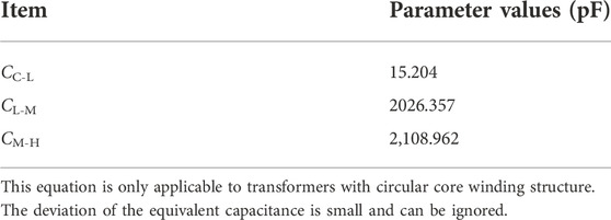
TABLE 2. Calculation value of equivalent capacitance of converter transformer.
Simulation and analysis of core grounding current of converter transformer by using analytical method
According to the circuit structure of the converter transformer shown in Figure 5 (a) and the parameters in Table 1 and Table 2, a calculation model of the converter transformer core single-point grounding current was established. Figure 7 shows the circuit simulation of 50HZ and 60 Hz AC grids connected by DC transmission.
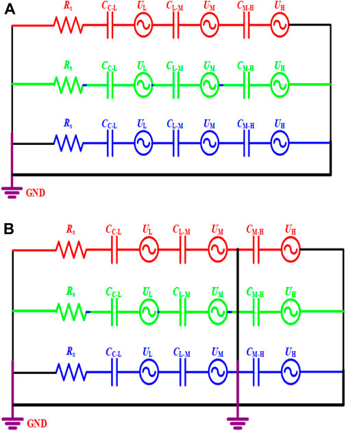
FIGURE 7. Single point grounding diagram of YN/YAI and YNynd11 cores: (A) YN/YAI structure; (B) YNynd11 structure.
As shown in Figure 8, the simulation circuit adopts a 750 kV HVDC transmission line with a length of 500 km. The Rectifier module includes three parts: the single-phase three-winding transformer (three in total, forming a three-phase transformer), a 12-pulse rectifier part. The Inverter module contains a single-phase three-winding transformer (a total of three, forming a three-phase transformer), a 12-pulse inverter part, and an equivalent circuit of core grounding current. Figure 9 shows the waveform and spectrum analysis results of the converter transformer single-point grounding current under different loads. Figure 10 shows the comparison of effective grounding current values of converter transformer single-point grounding under different loads.
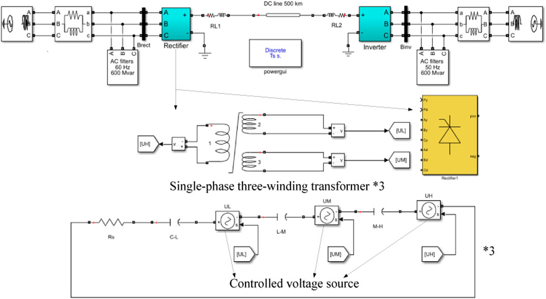
FIGURE 8. Simulation circuit converter transformer.
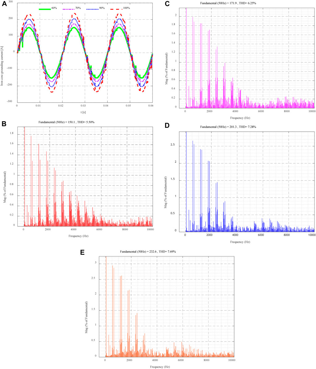
FIGURE 9. Waveform and spectrum analysis of single point grounding current of converter transformer under different loads: (A) Grounding current; (B) Current spectrum at 60% load; (C) Current spectrum at 70% load; (D) Current spectrum at 90% load; (E) Current spectrum at 100% load.
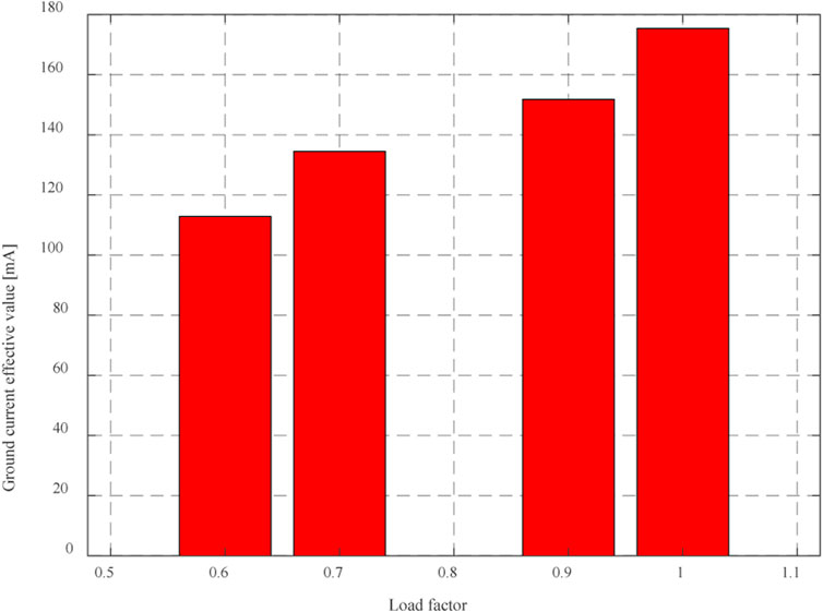
FIGURE 10. Comparison of single-point grounding current effective values of converter transformers under different loads.
Most converter transformers work under the condition of non-full load. This paper only considers the ground current analysis under the normal working condition of converter transformers.
It can be seen from Figure 8 that the grounding current of the converter transformer core increases with the increase of load rate. When the load rate increases to 100%, the effective value of the converter transformer core grounding current is 175.37mA, and the peak value reaches 201.3mA, which does not exceed the 300 mA limit specified by the power system. As can be seen from Figures 8B–E, with the increase in load rate, the harmonic distortion rate of the grounding current of the converter transformer core increases, and the maximum value is 7.69%.
Analysis of core grounding current of converter transformer by using FEM
For the FEM calculation of the single-point grounding current of the converter transformer core, in addition to the analysis of the general steps of finite element modeling, the average current density and equivalent resistance of the core under different load rates need to be calculated. Figure 11 shows the magnetic density distribution and excitation current waveform of the converter transformer under no-load conditions.
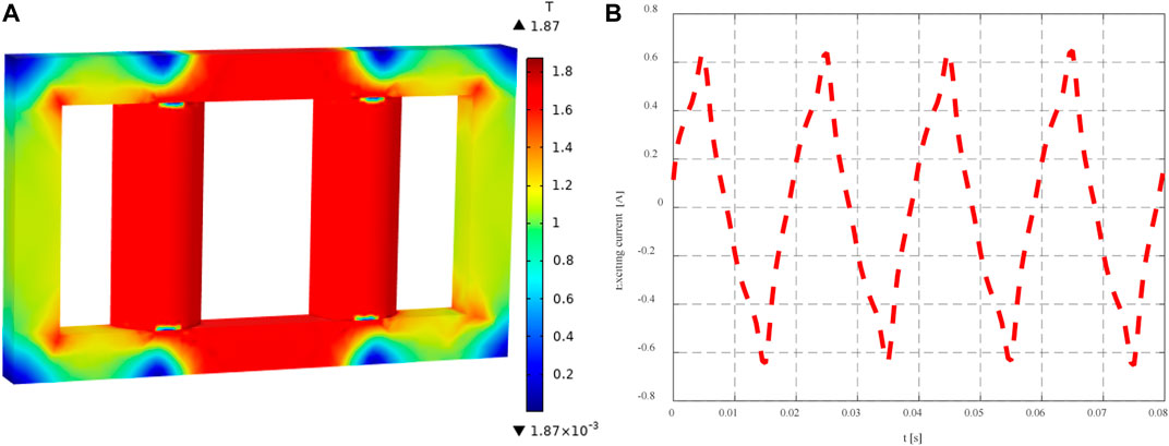
FIGURE 11. Magnetic density distribution and excitation current waveform of converter transformer under the no-load condition: (A) Magnetic density distribution of converter transformer; (B) Excitation current waveform.
As can be seen from Figure 12, the average magnetic density of the converter transformer core is 1.7T, and the effective value of excitation current is 0.43A, which verifies the correctness of the FEM in modeling, subdivision, materials, and other aspects.
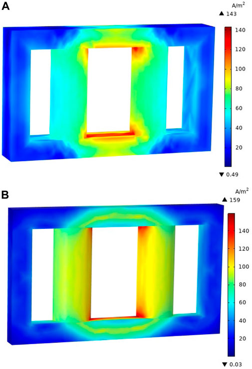
FIGURE 12. The current density of the converter transformer when the load rate of the converter transformer is 60% and 100%: (A) 60% load rate; (B) 100% load rate.
Figure 10 shows the converter transformer current density when the converter transformer load rate is 60% and 100%, and Table 3 shows the core grounding current when the converter transformer load rate is 60% and 100%.
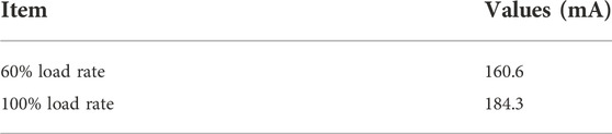
TABLE 3. The core grounding current when the load factor of the converter transformer is 60% and 100%.
Experimental study of core grounding current of converter transformer
Figure 13 shows the ground point and test point of the converter transformer core. Table 4 shows the comparison of the grounding current of the converter transformer core by analytical method, FEM, and experimental method.

FIGURE 13. Converter transformer core ground point and test point.
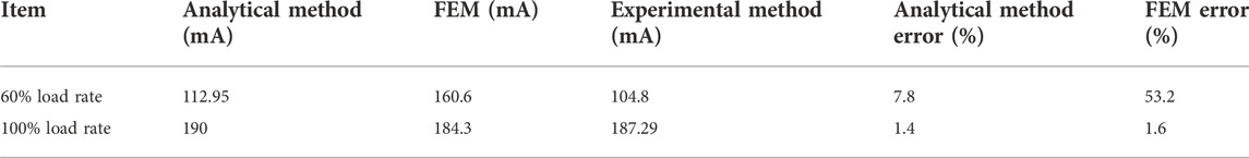
TABLE 4. Comparison of grounding current of the converter transformer core.
It can be seen from Table 4 that the analytical method has a deviation of 7.8% at a load rate of 60% and a deviation of 1.4% at a load rate of 100%, which meets the engineering requirements. The deviation of the FEM is 53.2% at 60% load rate, and the deviation is 1.6% at 100% load rate. There is no significant deviation in analytical calculation, the maximum is 1.6%. When converter transformer is 100% loaded, the deviation between analytical method and FEM is tiny, and analytical method is more accurate. In the calculation process, the influence of the homogenization of the iron core is not considered, and the conductivity of the iron core is constant, which causes more deviation.
Conclusion
In the actual operation of the converter transformer, the grounding current will be generated in the core. This paper carries out the calculation research on the grounding current of the converter transformer core.
1) Established the different winding connection modes of the converter transformer core Earth current equivalent circuit, based on the equivalent circuit of the converter transformer core Earth current under different load rates on the calculation, the research results show that the load rate, the greater the converter transformer core Earth current, the greater the calculation deviation is within 10%, conform to the requirements of the project.
2) Based on the finite element analysis, the core grounding current of the converter transformer is calculated and analyzed, and the deviation is analyzed.
3) The experimental research on the grounding current of the converter transformer core is carried out, and the correctness of the proposed scheme is verified by comparison with the analytical method and the FEM.
Data availability statement
The original contributions presented in the study are included in the article/supplementary material, further inquiries can be directed to the corresponding author.
Author contributions
XZ provided the ideas for the paper; TT edited the paper; PW performed the simulation-related work; YL and JB performed the theoretical analysis of the paper; NH conducted the experiments; and XL performed the final verification of the paper.
Funding
The Key Research and Development Program of Ningxia Hui Autonomous Region (2021BDE931018); Science and Technology Project of State Grid Ningxia Electric Power Co., LTD. (5229DK20004N).
The funder was not involved in the study design, collection, analysis, interpretation of data, the writing of this article, or the decision to submit it for publication.
Conflict of interest
Authors XZ, TT, PW, YL, JB, NH and XL were employed by State Grid Ningxia Electric Power Co Ltd., Electric Power Research Institute.
Publisher’s note
All claims expressed in this article are solely those of the authors and do not necessarily represent those of their affiliated organizations, or those of the publisher, the editors and the reviewers. Any product that may be evaluated in this article, or claim that may be made by its manufacturer, is not guaranteed or endorsed by the publisher.
References
Dai, Chenxin, Liu, Zhigang, Hu, Keting, and Huang, K. (2016). Fault diagnosis approach of traction transformers in high-speed railway combining kernel principal component analysis with random forest. IET Electr. Syst. Transp. 6 (3), 202–206. doi:10.1049/iet-est.2015.0018
Geng, Jianghai, and Wang, Ping. Current calculation during one point earthing of transformer core. TRANSFORMER 50 (04), 33–35.
Hamzehbahmani, H., Anderson, P., Hall, J., and Fox, D. (2014). Eddy current loss estimation of edge burr-affected magnetic laminations based on equivalent electrical network-Part I: Fundamental concepts and FEM modeling. IEEE Trans. Power Deliv. 29 (2), 642–650. doi:10.1109/tpwrd.2013.2272663
Ming-Cai, L., Jin, M., and Fu-Li, T. (2022). “Design of transformer iron core multi-point earthing automatic protection control system,” in Proceedings of the 2022 7th Asia Conference on Power and Electrical Engineering (ACPEE), Hangzhou, China, 1472–1476.
Wang, Qinghao, Zhang, Hua, Liu, Guobin, Zhang, Wenguang, Li, Na, Yang, Ying, and Ma, Guohai. “Transformer core accidents caused by loosing ground wire,” Singapore: IEEE PES Innovative Smart Grid Technologies, (2012) 1–3.
Zhang, Jin, Su, Minghong, Zhou, Dianbo, He, Yuhang, and Xiao, Yao. Grounding current of converter transformer core and its harmonic characteristics. TRANSFORMER 56 (09), 31–35.
Zhang, Jun, Zhan, Xiaobin, and Yi, Meisheng. Analysis for the reason for grounding current’s slight overload of transformer clamps. TRANSFORMER 56 (11), 40–44.
Zhang, Xiaohui, Wang, Maojun, Gao, Qiang, Liu, Qi, and Yuan, Feng. Reason Analysis and Countermeasures on Monitoring Abnormal Date of Converter Transformer Core Grounding Current. Northeast Electr. Power Technol. 38 (03): 59–62.
Keywords: transformer, core grounding current, analytic method, winding wiring model, calculation
Citation: Zhou X, Tian T, Wu P, Luo Y, Bai J, He N and Li X (2023) Analytical modeling and calculation of core grounding current in converter transformer. Front. Energy Res. 10:1074501. doi: 10.3389/fenrg.2022.1074501
Received: 19 October 2022; Accepted: 03 November 2022;
Published: 16 January 2023.
Edited by:
Dezhi Chen, Shenyang University of Technology, ChinaReviewed by:
Wenping Chai, Harbin Institute of Technology at Weihai, ChinaFuzhen Xing, Dalian Maritime University, China
Copyright © 2023 Zhou, Tian, Wu, Luo, Bai, He and Li. This is an open-access article distributed under the terms of the Creative Commons Attribution License (CC BY). The use, distribution or reproduction in other forums is permitted, provided the original author(s) and the copyright owner(s) are credited and that the original publication in this journal is cited, in accordance with accepted academic practice. No use, distribution or reproduction is permitted which does not comply with these terms.
*Correspondence: Tian Tian, dGlhbnQwNTMxQDE2My5jb20=