
94% of researchers rate our articles as excellent or good
Learn more about the work of our research integrity team to safeguard the quality of each article we publish.
Find out more
ORIGINAL RESEARCH article
Front. Energy Res. , 22 May 2019
Sec. Indoor Environment
Volume 7 - 2019 | https://doi.org/10.3389/fenrg.2019.00045
This article is part of the Research Topic New Materials and Design of the Building Enclosure View all 7 articles
 Vivian Ting Ting Chan1
 Matthew D. Ooms2
 Juergen Korn3Douglas MacLean4
 Stephen Mooney5Shane Andre2
 Phalguni Mukhopadhyaya1*
Glass fiber core vacuum insulation panels (VIPs) are becoming an increasingly attractive option for building envelope construction due to lower cost and availability around the world. Although fumed silica core VIPs have shown superior long-term performance under accelerated aging tests compared to glass fiber core VIPS, these laboratory test results have yet to be verified with long-term field performance data. In 2011, glass fiber core VIPs were installed in a commercial building retrofit project in Yukon, Canada (one of Canada's most northern territories), and have been continuously monitored since. This paper summarizes the thermal performance of the glass fiber core VIPs over the period of 2011–2018 in an extreme cold climate. Findings from this study provided data to validate glass fiber core VIP accelerated aging test results and the aging rate of VIPs in a cold and dry climate was determined. These results will help developing a better understanding of the long-term performance of glass fiber core VIPs in a real-world context.
Vacuum insulation panels (VIP) are one of the most promising advanced building insulation materials owing to their low thermal conductivity of about 0.004 W/m·K (Simmler et al., 2005). Traditional thermal insulation materials such as mineral wool, expanded polystyrene, extruded polystyrene, cellulose etc. are in the range of 0.025–0.040 W/m·K , have thermal conductivities 5–10 times higher than that of VIPs (Jelle, 2011). Integration of VIPs into building envelopes can help builders meet increasingly stringent code requirements, particularly when space is limited, and allow for greater aesthetic flexibility in architectural design. In spite of these benefits, VIPs have not been broadly adopted because of their high cost, concerns related to long-term effectiveness, thermal bridge effects at the panel edges, and the risk of condensation if appropriate moisture control is not considered in the design (Kalnaes and Jelle, 2014). It is worth mentioning that integration and adoption of new materials and technologies in the building construction industry takes time and cannot be done prior to rigorous short- and long-term holistic performance evaluation. This is particularly true in Canada1 or insulation because of the significant economic implications that can be expected should the insulation not perform as expected during Canada's long and very cold winters. In the case of VIPs, there are also related concerns about the effects of damage to VIPs during construction and in service, as well as the unknown service life for VIPs.
VIPs consist of an evacuated open-pore core enclosed within a gas-tight envelope, as shown in Figure 1. The core provides thermal resistance and adequate load bearing capacity to resist atmospheric pressure (Heinemann, 2017) while the single/multi-layer sealed envelope maintains the vacuum inside the panel. Opacifiers can be added to the core to reduce radiative heat transfer through the core, and getters/desiccants adsorb residual or permeating gas and moisture (Simmler et al., 2005) and thus slow the aging rate. In these ways, heat transfer across the panel is minimized and the service life is extended.
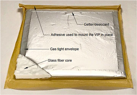
Figure 1. Schematic of a glass fiber core VIP. One corner of the gas-tight envelope has been removed to show the evacuated open-pore core. The getter/desiccant is in a sachet in the raised area at the top-center. The brown wax paper backing covers the adhesive that is used to mount the VIP in place.
To maintain high thermal performance, VIPs require their internal pressure to be kept very low, close to vacuum (zero). Permeation of dry air (e.g., oxygen and nitrogen) and water vapor through the envelope can compromise this vacuum and lead to an irreversible pressure increase and moisture accumulation inside the panel (Mukhopadhyaya, 2006). Temperature and relative humidity (RH) are the dominant factors impacting the rate of gas permeation through the envelope and consequently the VIP's expected service life.
The most commonly used VIP core materials are fumed silica and glass fiber. Fumed silica core VIPs can achieve thermal conductivities of 0.004 W/m·K when the pore pressure is reduced to 2,000–10,000 Pa at room temperature. Fumed silica has a pore size of about 30–100 nm and its thermal characteristics are stable up to about 5,000 Pa (Simmler et al., 2005). Among core materials, fumed silica is least sensitive to increases in pressure, and its internal pressure can be satisfactorily maintained with a moderately effective gas-tight envelope. Fumed silica VIPs with laminated aluminum foil envelopes are expected to have service lives of up to 50 years (Simmler et al., 2005; Fricke et al., 2006). Furthermore, even after complete vacuum failure, fumed silica core VIPs can have thermal resistances twice as high (thermal conductivity = 0.020 W/m·K) as conventional insulation materials (Simmler et al., 2005).
In comparison, glass fiber VIPs are able to achieve thermal conductivities as low as 0.002 W/m·K, the lowest of all core materials (MacLean and Korn, 2011) although they require an internal pressure of about 10 Pa to achieve this performance. In addition, the larger pore size (1–12 μm) of glass fiber cores leads to a rapid increase in thermal conductivity when the internal pressure rises above 100 Pa (Fricke et al., 2006). Nevertheless, glass fiber core VIPs are less expensive to manufacture and therefore remain an attractive alternative as a building material (Simmler et al., 2005). Glass fiber VIPs have been used extensively in the aerospace and refrigerator industries where the expected service life is no more than 15 years (Simmler et al., 2005). While the expected service life of thermal insulation in building construction is 25–50 years, broad industry confidence in long-term thermal performance of glass fiber core VIPs still needs to be established.
Glass fiber core VIPs have been used as thermal insulation in retrofitting an existing wall of a commercial building in Whitehorse, Yukon, a subarctic city in Northern Canada. Buildings in Whitehorse typically have high space-heating demands due to the region's extremely cold winters, so interest in high performing building insulation systems is high. This paper is a continuation of a series of publications (MacLean and Korn, 2011; Mukhopadhyaya et al., 2011, 2013, 2014, 2017; MacLean et al., 2017) and presents the most up-to-date field performance data observed from continuous in situ monitoring of this installation (2011–2018), compares these results to accelerated aging test results presented in the literature, and discusses the lessons learned from VIP handling and installation.
An 8.4 × 3.7 m2 wall of an existing building was retrofitted with VIPs sandwiched between layers of extruded polystyrene foam (XPS) attaching to its concrete exterior. The VIP specimens used were 560 × 460 × 12 mm in size. The pre-installation thermal conductivity of the VIPs was measured using a 600 × 600 mm heat flow meter apparatus with 300 × 300 mm heat flow sensor and an accuracy of ± 2%, the thermal conductivity was found to be 0.0034 W/m·K at the center of the panel (Mukhopadhyaya et al., 2014).
The existing exterior concrete block wall (Figure 2) was insulated with fiberglass batts. The thermal resistance of this existing wall was about 3.5 m2.K/W, and the retrofitting goal was to increase the wall's thermal resistance to 8.8–10.6 m2.K/W (Mukhopadhyaya et al., 2014). The integrity of VIPs was verified by physical examination at the construction site before the assembly. Concerns regarding condensation in additional wall layers and mechanical rubbing on VIP surfaces caused by uneven proximate wall elements were addressed in the design described below (Mukhopadhyaya et al., 2014). In summary, additional layers of insulation were constructed on the exterior of the existing concrete block wall in the following order (Mukhopadhyaya et al., 2014):
- First, a 0.15 mm polyethylene air-vapor-moisture barrier was glued to the concrete block wall to minimize condensation in extra wall layers.
- Then, 25 mm extruded polystyrene (XPS) board was adhered to the polyethylene barrier, creating an even surface for subsequent mounting of the VIPs.
- 50 × 75 mm wood strapping was then attached over top of the XPS board and affixed to the concrete wall with anchors.
- Glass fiber core VIPs were adhered to the XPS board between the wood straps, using a “peel and stick” adhesive on one side.
- The VIPs were then covered with a layer of 6 mm flexible polyurethane foam that was held in place with sheathing tape.
- Lastly, a layer of 25 mm thick polystyrene board was installed over the polyurethane foam to avoid the potential risk of condensation and damage from mechanical rubbing.
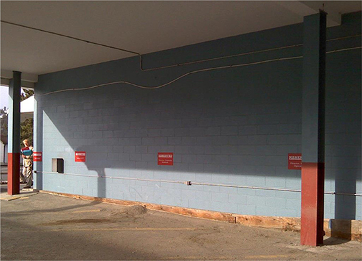
Figure 2. Existing wall selected for retrofit (MacLean and Korn, 2011).
Installations proceeded quickly and smoothly as documented in Figures 2–5.
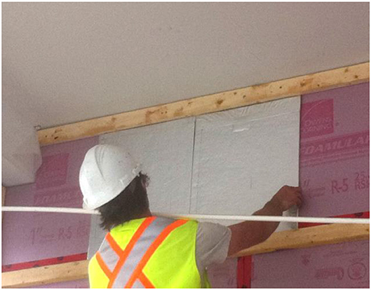
Figure 3. Installation of VIPs over a layer of XPS and a 0.15 mm (6 mil) polyethylene air vapor barrier on the existing concrete block wall (MacLean and Korn, 2011).
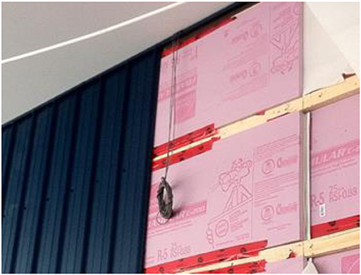
Figure 4. The second layer of XPS is shown in place over 6 mm polyurethane foam. The XPS layer ensured that the bottom surface of each VIP was attached to a smooth surface and protected from abrasion. A layer of 6 mm flexible polyurethane foam was placed over the exterior surface of the VIPs to help prevent mechanical rubbing of the outside surface of each VIP against the 25 mm polystyrene foam board placed on top of it.
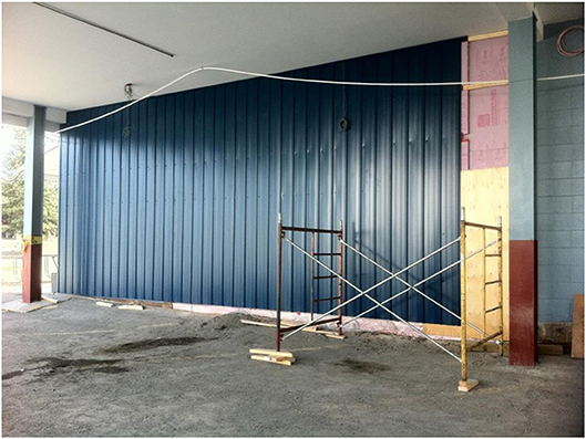
Figure 5. Post-retrofit wall (MacLean and Korn, 2011). Because all holes for fasteners were drilled before the siding was put on the wall, it was possible to visually check that all fastening points were directly over the support members.
Four thermistors were installed to monitor the temperature at the interface between insulation layers, as shown schematically in Figure 6. These thermistors were set up ~2 m from the south edge of the wall and 1 m down from the top of the wall (Mukhopadhyaya et al., 2014). Three sensors were placed on the existing wall ~2 m from the north edge of the wall retrofitted area. These sensors were located ~1, 1.5, and 3 m from the top of the wall, and they were used to monitor the thermal gradients from the top to the bottom of the wall (Mukhopadhyaya et al., 2014).
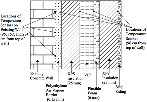
Figure 6. Schematic diagram of the retrofitted wall cross-section starting from cladding onwards and the locations of the temperature sensors (thermistors) (MacLean and Korn, 2011). This drawing is not to scale. Two sets of thermistors are installed at different locations along the length of the wall (one set is near the north edge and the other is near the south edge).
Infrared thermal images of the retrofitted wall were taken in 2011, 2014, 2016, and 2018 are shown in Figure 7. These images confirm that all VIPs installed in 2011 remain functional after 8 years. Specifically, it is clear from the temperature of the wall over each VIP that none of the VIPs have lost their insulating value over 8 years (failed VIPs will be indicated by abrupt change of color in the infrared thermal images). This is a very significant finding for the long-term performance of glass fiber core VIPs in an extreme cold climate and demonstrates the effective integration of VIPs in an exterior building envelope retrofit. In order to gain greater insight into the thermal performance of the exterior wall and VIPs, the temperatures at the interfaces between insulation layers of the retrofitted wall were collected over the past 8 years (2011–2018) since the project started, and selected data were analyzed for the following colder winter time periods (summer data were not stable due to factors such as lack of thermal gradient, unstable indoor condition etc.):
• December 13, 2011–April 15, 2012
• December 5, 2012–May 23, 2013
• November 1, 2013–January 9, 2014
• February 11, 2016–March 31, 2016
• November 1, 2016–January 11, 2017
• March 24, 2018–June 8, 2018
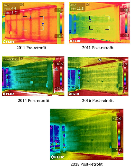
Figure 7. Infrared images of the pre-retrofit and post-retrofit wall. Images were taken in 2011, 2014, 2016, and 2018.
The temperature drops across each layer of the composite exterior insulation (XPS-VIP-XPS) were calculated as a percentage of total temperature drop across the composite exterior insulation. A sample calculation can be found in Appendix A. Figure 8 shows the percentage of total temperature drop across each insulation layer averaged over the winter and/or spring months for six selected years. The average temperature drop for the VIP layer is about 66.49%, while that for the first (interior) and second (exterior) layers of XPS are 14.48 and 18.95%, respectively. The exterior layer of XPS is a more effective thermal insulator than the identical interior XPS layer due to the cooler exterior temperature. This observation clearly validates a very basic physical principle of heat transfer and generates confidence in the recorded data and the analysis procedure. The graphical representation in Figure 8 shows that the effectiveness of the VIP layer is decreasing very slowly, from about 69% initially in winter 2011 to 63% in spring 2018, at an average rate of 0.9% per annum, and this rate of aging appears to be linear. However, it is to be noted that the aging rate of VIPs cannot be linear forever and it is expected to increase rapidly as the internal pressure approaches atmospheric pressure. The transition from lower aging rate to higher aging rate depends on the functional relationship between thermal conductivity and internal pore pressure of the VIP core material.
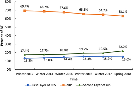
Figure 8. Percentage of temperature drop across wall components, relative to the drop across the entire wall. Data averaged for the winter months 2011–2017 and spring months of 2018.
Accelerated aging tests were conducted, at the National Research Council (NRC) Canada, in 2011 to establish long-term thermal performance of the glass fiber core VIPs used in this study (Mukhopadhyaya et al., 2014). Three VIP specimens (560 × 460 × 12 mm) were tested under cyclic exposure conditions. In one cycle, VIPs were kept at 23°C, 95% RH for 1 week and then changed to 70°C, 5% RH for the next week. The specimens went through 14 weeks of total exposure (i.e., a total of seven cycles). The thermal resistance of the panels was measured at the end of each week using a 600 × 600 mm heat flow meter. One specimen failed after 8 weeks, and the average linear aging rate of the other two was found to be about 3.29% (Morlidge, 2012) per cycle as shown in Figure 9. The normalized in situ VIP aging rate (expressed as the percentage of its initial thermal resistance) was also plotted with the average of accelerated aging test results in Figure 9. It can be observed from the plot, that the 2-year in situ aging rate is nearly equal to one cycle (two weeks) of the accelerated aging rate for the time period where field data are available. Based on this correlation, the linear extrapolation of the in situ data predicts that the total reduction of thermal resistance in 2026 (14 years since construction) will be about 21% (thermal conductivity increased from 0.0034 to 0.00429 W/m·K).
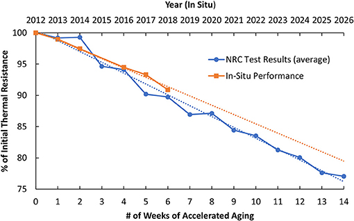
Figure 9. Aging rate of glass fiber core VIP in terms of its pristine thermal resistance as a function of time determined from in situ performance and laboratory accelerated aging test results.
The small divergence between the accelerated aging test and the actual field performance of VIPs could be attributed to the different environmental (boundary) conditions that the VIPs were exposed to. Accelerated aging tests were conducted with the exposure in cyclic conditions of extreme high temperature and relative humidity (23°C, 95% and 70°C, 5%), while the in situ performance study was carried out in the subarctic climate of Whitehorse, Yukon with lower temperatures and high RH [an average of −13°C and 75% RH over winter months and an average of 11.5°C and 62% RH over summer months]2. Since the permeability of gas through the VIPs envelope increases with temperature, the VIP aging rate is slower when subjected to lower temperatures. It is also to be noted that the XPS foam on both sides of the VIPs resisted water vapor movement and absorbed some amount of water vapor, thus buffering the VIP's exposure to moisture. Overall, the linear aging trends from in situ measurements and laboratory accelerated aging test results are quite similar. Additional field and accelerated aging test observations are required to elaborate on the relationship between VIP type, environment and comparison to laboratory tests and to establish more general rules or protocols for the prediction of long-term performance of glass fiber core VIPs.
The typical relationships between the thermal conductivity and internal pore pressure for glass fiber and fumed silica core VIPs are shown in Figure 10 (Fricke et al., 2006). These relationships clearly indicate that the rate of increasing thermal conductivity with pore pressure (i.e., the aging rate) of VIPs is not linear during their service life. Derived from Figure 10, 11 shows the aging of glass fiber and fumed silica core VIPs in terms of their initial thermal resistance as a function of internal gas pressure.
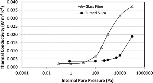
Figure 10. Typical thermal conductivity of glass fiber and fumed silica VIPs as a function of internal pore gas (air) pressure (Heinemann, 2017).
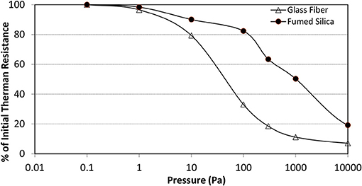
Figure 11. Aging of glass fiber and fumed silica core VIPs in terms of their initial thermal resistance as a function of gas (air) pressure (derived from Figure 10).
Figure 11 indicates that glass fiber core VIPs lose about 20% of their initial thermal resistance when the internal pore pressure reaches about 10 Pa and that this change of thermal resistance is almost a linear function of time. However, Figure 10 also shows that the thermal conductivity of glass fiber core VIPs will rise at a much faster rate between an internal pressure of 10 Pa and 100 Pa, but still thermal conductivity stays below 0.007 W/m·K at 100 Pa internal pore pressure. These observations further reinforce the relationship between accelerated aging and in situ performance of glass fiber core VIP presented in the previous section. Though in situ decrease in the thermal resistance is found to be slow and vary linearly with time until now. It is expected that the thermal resistance of glass fiber core VIPs will eventually decrease at a much faster rate. Hence, the in situ performance observations in the coming years will be of particular interest and will help us to establish the true relationship between accelerated aging test results and the long-term in situ performance of glass fiber core VIPs.
The results from the energy retrofit project in the Canadian subarctic climate in Whitehorse, Yukon, using a foam-VIP-foam sandwich (i.e., XPS-VIP-XPS) insulation have demonstrated the promising and satisfactory performance of glass fiber core VIPs over a period of 8 years. Analysis of the temperature data from monitoring each insulation layer over a period of 8 years (2011–2018) has shown a <0.9% per year change in the field thermal performance of the VIPs, which indicates that aging of glass fiber core VIPs in cold climate proceeds at a very slow rate. Moreover, this project has shown that many perceived challenges (i.e., handling, installation, etc.) relating to the application of VIPs in the construction industry could be addressed through careful planning and detailing. Ongoing in situ temperature monitoring of this project provides valuable field data that can be used for validating theoretical VIP aging predictions and laboratory accelerated aging results.
All authors listed have made a substantial, direct and intellectual contribution to the work, and approved it for publication.
Funded by Energy Mines and Resources (Yukon Government).
The authors declare that the research was conducted in the absence of any commercial or financial relationships that could be construed as a potential conflict of interest.
The authors appreciate the support of Panasonic Canada Inc. and Panasonic Corporation for supplying the vacuum insulation panels used for this project. The authors gratefully acknowledge the National Research Council Canada (NRCC) for providing technical expertise and support. The authors would like to thank Yukon Housing Corporation for providing a wall on one of their buildings for this project, and for providing monitoring equipment and for assistance with data collection and handling. Cold Climate Innovation, Yukon Research Centre, Yukon College, and the Energy Solutions Centre must also be credited for providing financial and technical supports for this collaborative project.
The Supplementary Material for this article can be found online at: https://www.frontiersin.org/articles/10.3389/fenrg.2019.00045/full#supplementary-material
1. ^Canadian Construction Materials Centre—About the CCMC, National Research Council Canada, 16 11 2016. Available: https://www.nrc-cnrc.gc.ca/eng/solutions/advisory/ccmc/about_ccmc.html. (accessed January, 2019).
2. ^Climate and Weather Averages in Whitehorse, Yukon, Canada. Time and Date, 1995-2017. Available online at: https://www.timeanddate.com/weather/canada/whitehorse/climate. (accessed June11, 2017).
Fricke, J., Schwab, H., and Heinemann, U. (2006). Vacuum insulation panels - exciting thermal properties and most challenging applications. Int. J. Thermophys. 27, 1123–1139. doi: 10.1007/s10765-006-0106-6
Heinemann, U. (2017). Long-Term Performance of Super-Insulating Materials in Building Components and Systems. Energy in Buildings and Communities Programme.
Jelle, B. (2011). Traditional, state-of-the-art and future thermal building insulation materials and solutions - properties, requirements and possibilities. Energy Build. 43, 2549–2563. doi: 10.1016/j.enbuild.2011.05.015
Kalnaes, S., and Jelle, B. (2014). Vacuum insulation panel products: a state-of-the-art review and future research pathways. Appl. Energy 116, 355–375. doi: 10.1016/j.apenergy.2013.11.032
MacLean, D., and Korn, J. Mukhopadhyaya, P. (2011). “Vacuum Insulation Panels (VIPs) Arrive in Northern Canada: Institutional Building Pilot Retrofit in Yukon,” in Proceedings of 10th International Vacuum Insulation Symposium (IVIS-X) (Ottawa, ON), 10.
MacLean, D., Mukhopadhyaya, P., Korn, J., and Mooney, S. (2017). Design details and long-term performance of VIPs in Canada's North. Energy Proc. 111, 481–489. doi: 10.1016/j.egypro.2017.03.210
Morlidge, M. (2012). Determining the aging performance of vacuum insulation panels: development of a prediction model (MASc thesis). Ryerson University, Toronto, ON, Canada.
Mukhopadhyaya, P. (2006). High Performance Vacuum Insulation Panel - Research Update From Canada. Global Insulation Magazine, 9–15.
Mukhopadhyaya, P., Kumaran, M. K, and Sherrer G. van Reenen, D. (2011). “An investigation on long-term thermal performance of Vacuum Insulation Panels (VIPs),” in Proceedings of 10th International Vacuum Insulation Symposium (IVIS-X) (Ottawa, ON), 10.
Mukhopadhyaya, P., MacLean, D., Korn, J., and Mooney, S. (2017). Application of VIPs in Canada's North - Monitoring Results' ASTM International, STP1599. West Conshohocken, PA: ASTM International, 122–131.
Mukhopadhyaya, P., MacLean, D., Korn, J., van Reenen, D., and Molleti, S. (2013). “Field application and long-term thermal performance of Vacuum Insulation Panels (VIPs) in Canadian Arctic Climate,” in Proceedings of 11th International Vacuum Insulation Symposium (IVIS-XI), 97–98.
Mukhopadhyaya, P., MacLean, D., Korn, J., van Reenen, D., and Molleti, S. (2014). Building application and thermal performance of vacuum insulation panels (VIPs) in Canadian subarctic climate. Energy Build. 85, 672–680. doi: 10.1016/j.enbuild.2014.08.038
Simmler, H., Brunner, S., Heinemann, U., Schwab, H., Kumaran, K. P., Mukhopadhyaya, P., et al. (2005). Study on VIP-Components and Panels for Service Life Prediction of VIP in Building Applications (Subtask A). HiPTI - High Performance Thermal Insulation, IEA/ECBCS Annex 39, 1–159. Available online at: https://en.wikipedia.org/wiki/R-value_%28insulation%29
Keywords: vacuum insulation panel (VIP), glass fiber core, in situ performance, accelerated aging test, cold climate
Citation: Chan VTT, Ooms MD, Korn J, MacLean D, Mooney S, Andre S and Mukhopadhyaya P (2019) Critical Analysis of in situ Performance of Glass Fiber Core VIPs in Extreme Cold Climate. Front. Energy Res. 7:45. doi: 10.3389/fenrg.2019.00045
Received: 15 November 2018; Accepted: 24 April 2019;
Published: 22 May 2019.
Edited by:
Kaushik Biswas, Oak Ridge National Laboratory (DOE), United StatesReviewed by:
Mohammadhasan Fathollahzadeh, Colorado School of Mines, United StatesCopyright © 2019 Chan, Ooms, Korn, MacLean, Mooney, Andre and Mukhopadhyaya. This is an open-access article distributed under the terms of the Creative Commons Attribution License (CC BY). The use, distribution or reproduction in other forums is permitted, provided the original author(s) and the copyright owner(s) are credited and that the original publication in this journal is cited, in accordance with accepted academic practice. No use, distribution or reproduction is permitted which does not comply with these terms.
*Correspondence: Phalguni Mukhopadhyaya, cGhhbGd1bmlAdXZpYy5jYQ==
Disclaimer: All claims expressed in this article are solely those of the authors and do not necessarily represent those of their affiliated organizations, or those of the publisher, the editors and the reviewers. Any product that may be evaluated in this article or claim that may be made by its manufacturer is not guaranteed or endorsed by the publisher.
Research integrity at Frontiers
Learn more about the work of our research integrity team to safeguard the quality of each article we publish.