 Shouquan Tang1Minhong Li1Hong Xie1Zhenzi Wang1Peng Yu1Zhonghang Li1Zhe Wang1Tengbiao Chen1
 Bangzhu Wang2*
- 1Shenzhen Power Supply, China Southern Grid Co., Ltd., Shenzhen, Guangdong, China
- 2School of Electrical Engineering, Beijing Jiaotong University, Beijing, China
High-temperature superconducting (HTS) cable can transmit massive power with little dissipation in a limited corridor, which is an attractive solution for future power transmission. Shenzhen Power Supply energized a 400 m/10 kV/2.5 kA concentric HTS cable system on 28 September 2021 to power Ping’an Financial Centre, a Shenzhen’s landmark building, which was the debut of concentric HTS cable made of YBCO in the urban area of a megacity. For more than 1 year, the HTS cable system has been operating well and will continue to operate for a long time. This paper systematically reviews the system specification, cable and its accessories design, cryogenic cooling system design, type and exploratory test, project construction, pre-commissioning test, and operation of the demonstration cable system. Based on our R&D practice, we identify that cost, long-term reliability, and operational simplicity are the main hinders factors that need to be addressed to advance the large-scale application and we propose a set of solution ideas meanwhile.
1 Introduction
High temperature superconductors (HTS or high-Tc), whose critical temperature are above the boiling point of cheap and easily accessible liquid nitrogen (LN2), boost the large-scale power applications. Over the last 3 decades, HTS have matured, especially due to the technical progress achieved in the manufacturing, application, and measurement of these materials and in the enable techniques such as high capacity LN2 cooling, low temperature insulation and so on. HTS cable, with the merits of massive power transmission capacity, super low resistive losses, narrow corridor occupation, and environmental friendliness, has received serious attention and expectations from academia, industry, and power grid (Doukas, 2019). On 28 May 2001, a 30 kV/2 kA 30 m long HTS cable developed by NKT and its partners was put into operation in Denmark for the first time (Ostergaard and Tonnesen, 2002). From then on, several demonstration projects with various featured parameters have been carried out in United States, China, Japan, Korea, Russia and EU (Ueda et al., 2003; Honjo et al., 2011; Thomas et al., 2016; Chikumoto et al., 2018; Lee et al., 2018; Hajiri et al., 2022).
During the HTS cable development, three configurations have been engineered and made practical for alternate current (AC) power transmission. They are single core, three-in-one (or triad, three-core), and concentric (or triaxial). Based on different rated voltage and current, short-current level, cable length, and footprint requirement, a certain type will be the optimum. In the urban distribution grid, generally with limited corridors and low voltage levels (typically in the range of 6–35 kV), concentric type HTS cable becomes the best option. Since the three phases are concentric, when the phase currents are balanced there is no net magnetic field and induced current so that it does not have to use a superconducting shield layer. Compared to single core or three-in-one type, concentric type uses about half the HTS tapes and so the cable cost is reduced. Furthermore, as the size is more compact than the other two and fits in a single, smaller cryostat, the concentric cable has lower heat load, which reduces the burden on cable cooling system and saves the valuable cryogenic resources (Young et al., 2005; Ha et al., 2013; Miyagi et al., 2018; Xu et al., 2022).
The first concentric-type HTS cable was developed by Ultera Inc. and energized at AEP Bixby Substation in Columbus, Ohio, United States in 2006. The cable is 200 m long and connects a 138/13.2 kV transformer to the distribution switchgear with a capacity of 69 MVA. It uses BSCCO tapes and was designed to carry 3000 A (Demko et al., 2007). The main cooling source was a vacuum-based subcooled system and after 2 years a pulse tube cryocooler was integrated in parallel (Chen et al., 2010). This project certified the feasibility and technical advantages of concentric HTS cable.
In 2014, another concentric HTS cable was put into operation in Essen, Germany. The so called “Ampacity” HTS cable project was led by RWE and achieved a milestone in HTS concentric cable R&D. The cable was 10 kV/40 MVA and 1,000 m long with an intermediate joint, which was the longest HTS cable in the world at that time. It had been evaluated as an economical alternative to conventional 110 kV cables (Stemmle et al., 2013). Ampacity brought HTS concentric cable to a new level, in which environmentally-friendliness, reliability, and affordability were seen much more clearly and tangibly (Buchholz et al., 2021).
Shenzhen, located on the east bank of the Pearl River estuary on the central coast of Guangdong Province, is one of the most populous cities in China. In recent years, the power load has been continuous growing in urban central areas. However, the corridors for transmission lines are saturated and the lands for substations are lacking. Based on the realistic urgent needs, Shenzhen Power Supply, a branch of China Southern Grid Co., launched a HTS cable demonstration project in urban distribution network in 2016. The project aimed to build a 400 m/10 kV/2.5 kA concentric HTS cable to supply power to high load density CBD areas. After several years of technical R&D and series of tests, on 28 July 2021, the 400 m superconducting cable for the demonstration project was laid successfully. On 28 September 2021, the cable system was energized and began to supply power for Ping’an Financial Centre, Shenzhen’s landmark building. Shenzhen’s HTS cable was the third HTS concentric cable throughout the world and the first one using YBCO tapes. It was also the world’s first superconducting power cable applied to the center area of a megacity.
In this paper, we will systematically review the details of the Shenzhen HTS con-centric cable system from system design parameters and considerations to construction and testing matters of the demonstration project. We also give a brief introduction to the operation experience and challenges issues of HTS power cable system.
2 Materials and methods
2.1 HTS cable system in the grid configuration
The HTS cable is in Futian CBD, one of the most populous areas in Shenzhen. In the past, Binhe substation supplies Xinghe substation by 110 kV cables and in Xinghe, the voltage is reduced further to 10 kV to supply the terminal customers. Based on the low-voltage and high current characteristics of HTS cable, we reduce the 110 kV level and use HTS cable to directly connect the 10 kV bus 3 M in Binhe and the 10 kV bus 4 M in Xinghe, as shown in Figure 1. The HTS cable system is mainly consisted of concentric HTS cable and its accessories, cryogenic cooling subsystem, and control and protection subsystem. Below we will introduce each of them.
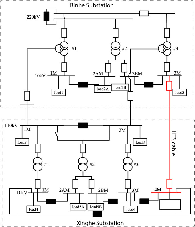
FIGURE 1. Logic location of Shenzhen HTS cable in the grid.
2.2 Concentric HTS cable design
The concentric HTS cable core consists of former, three concentric arranged HTS tapes layers with their electric insulation layers made of polypropylene laminated paper (PPLP), a Cu screen layer, and a glass fiber protecting layer. The HTS cable core is placed inside the cryogenic pipe, which is thermal insulated by multilayer insulation (MLI). Outside the cryogenic pipe is the PVC protecting layer. The 3D structure model of the concentric HTS cable is shown in Figure 2 and Table 1 describes the specifications in detail.
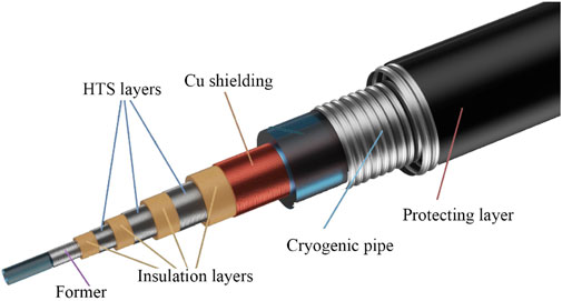
FIGURE 2. Shenzhen HTS cable structure.
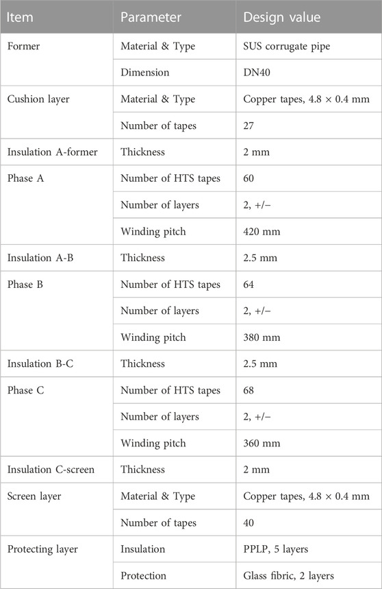
TABLE 1. Specifications of the concentric HTS cable core.
The YBCO Superconductor tapes are produced by Shanghai Superconductor Co., Ltd. Its self-field critical current (Ic) is 120 A at 77.3 K and has a dimension of 4.3 × 0.38 mm. To obtain an improved fault current tolerance capability, we choose the thick HTS tape, which has two 180 μm reinforcing copper layers, one on each side of the superconducting layer. The rated current of the HTS cable is 2.5 kArms. As the power grid may encounter various transient conditions, we consider a current fluctuation factor k1 mainly for possible system overload operation and an engineering margin factor k2 for system safety. The designed DC Ic of each phase is 6 kA@77 K & self-field.
PPLP has good mechanical and electrical performance at LN2 environment. The thickness of insulation layer is determined by the withstanding voltage. We insulated phase A from the former so that the former could be connected directly to the cryogenic system piping and the termination shell could earthing directly for protective purpose. After considering safety factors, the thickness of the insulation layers withstanding the line-voltage (phase A to B and phase B to C) are set to 2.5 mm and those withstanding the phase voltage (others) are set to 2 mm. In conjunction with every insulation layer, semiconducting carbon paper layers are employed. They will provide the conducting layers a relatively smooth surface so that the electric fields are homogenized, and the partial discharge (PD) is suppressed.
The function of cushion layer is to smooth out the surface of the former as the former is corrugated pipe. Thus, the electric field of phase A to former could be more symmetrical. In addition, the cushion layer also helps to reduce the folds formation possibility in phase A-former insulation, that is why we call it cushion layer. The protecting layer serves to fasten and protect the cable core. During transportation and laying, etc., the cable core may have relative displacement inside the cryostat and the protecting layer could prevent the cable core from being scratched or other damages.
Based on the dimension of HTS cable core, we designed the inner pipe to be DN110 and the outer one DN170. The pipes were made of stainless steel 304 L and corrugated. MLI technique is used to achieve a good thermal performance (Gouge et al., 2008). By adopting laser-based continuous welding and forming technique, we were able to make the vacuum-insulated flexible cryostats with lengths up to ∼500 m, which matched our cable length well. To speed up the evacuation of the cryostat, we set up 2 taps in the middle. The outermost sheath is extruded Polyvinyl Chloride (PVC). The specifications of the design (such as corrugated height and pitch) are listed in Table. 2.
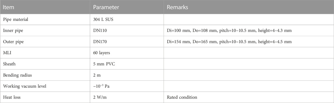
TABLE 2. Specifications of the concentric HTS cable core.
2.3 Cable termination design
The termination is mainly consisted of cryostat, current lead, and high voltage (HV) bushing. And the termination is also the interfaces of cooling liquid, measurement lines, and valve controls.
The current lead connects the superconductors and the grid. Multifilament copper flexible wires bundle was used to avoid skin effect and to reduce the appearance cross-section of the lead. The length and cross-section of lead were optimized to minimize the heat loss (Rasmussen and Rasmussen, 1999). In our design, the current lead length was 950 mm and the cross-section was 600 mm2. The heat loss of a current lead under rated condition was about 45 W/kA.
In our practice, we found that the resin impregnated fiberglass (RIFG) HV bushing could degrade its performance under LN2 temperature and even occurred cracking or damage. To verify the HV bushing design, we conducted a series of tests. The performance under LN2-to-ambient thermal cyclic shock was focused. We submerged the HV bushing into LN2 to cool it down rapidly and let it stay for 15 min at least until it was completely cold, then pulled it out and warmed it up to room temperature as shown in Figure 3. We did that for 5 cycles and after each cycle, the capacitance and partial discharge were measured. Only those of no significant changes can be utilized.
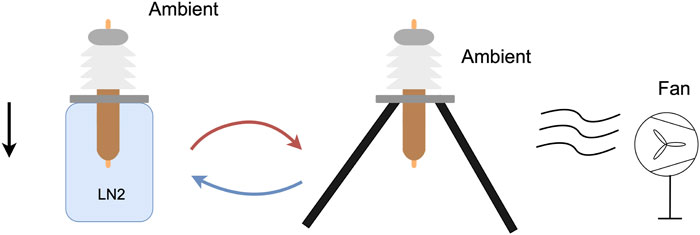
FIGURE 3. Procedure of LN2-to-ambient thermal cyclic shock test of RIFG HV bushing.
Although both the possible voltage and current of the shielding layer are quite low, we chose the same HV bushing as the conductor phase and smaller cross-sectional area lead for it for the sake of component replaceability and appearance aesthetics. For ease of installation, limiting and fixing, and for shrinkage compensation during cooling, we mounted the termination on a support frame with rails. Figure 4 shows the termination profile.
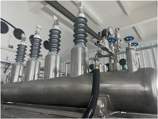
FIGURE 4. The termination.
2.4 Cryogenic cooling subsystem design
Since the cryogenic cooling system is an enabling condition for the normal operation of superconducting cables, its stability and reliability have an important impact on the stability and reliability of the superconducting cable system.
The cryogenic cooling system includes refrigerators as cooling source, LN2 pump, heat exchanger, LN2 storage tank, piping, valves, sensors, and instrumentation as shown in Figure 5. To improve the availability, two parallel connected LN2 pumps were employed, and a backup cooling source was installed. The maximum pressure in normal working conditions of the system was 0.5 MPa. The equipment, valves, and safety devices in the cryogenic cooing system were selected and configured accordingly.
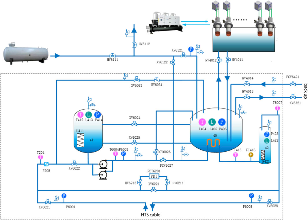
FIGURE 5. Schematic of cryogenic cooling subsystem.
The major cooling source was provided by GM refrigerators made by CSIC Pride Cryogenic Technology Co., Ltd., one of 77 K GM refrigerator providers in China. We used 28 GM refrigerators, and the total cooling power was about 7 kW at 70 K, which could match the 5 kW thermal load of the HTS cable system and left some margin to cover the heat loss increment caused by vacuum degradation and other unpredictable factors.
Each cold head was mountable and can be maintained in turn without disturbance of the working cooling power. To a certain extent, this configuration improved the reliability of the cryogenic cooling system.
The backup cooling system was an active evaporating system, and it was consisted of evacuation pump with its heating component and other accessories. It worked only when the GM refrigerators could not provide enough cooling power.
We adopted the counterflow manner to cool the HTS cable, where subcooled LN2 from the cryogenic cooling system flowed in through the former in one termination and turned back at the other termination then came to the cryogenic cooling system through the gap between the cable core and the inner pipe.
2.5 Type test and research tests of 30 m prototype system
To fully validate the system design, a 30 m prototype system (Figure 6) was developed. We conducted type test on the prototype according to IEC 63075 and Chinese National Standards, the results had been reported in our earlier paper (Wang et al., 2021). In addition, we have conducted a lot of research experiments, such as AC loss, shielding layer current under unbalance, overcurrent shock, and so on.
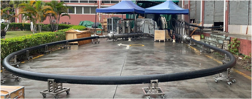
FIGURE 6. The 30 m prototype under overcurrent and other research tests.
It is worth mentioning that we conducted a series of overcurrent-duration combinations to simulate of the worst cases of three-phase short-circuit faults. The test could examine the endurance and stability of HTS cable under fault conditions. The maximum test overcurrent reached 32 kA with a duration of 143 ms, as shown in the Figure 7 below. After the overcurrent shock tests, we checked the critical current of each phase, no observable degradation has occurred. The overcurrent shock test directly verified the thermal stability of the HTS cable system. It also provided a basis for the setting of the protection system of HTS cable system and the integrated local grid.
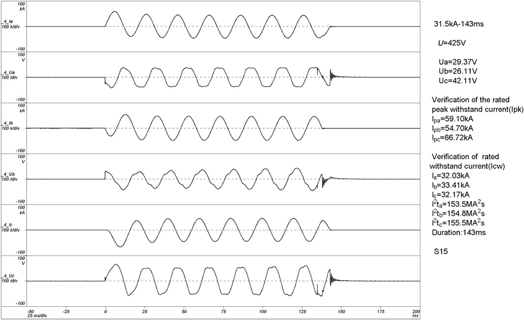
FIGURE 7. The waveform of overcurrent shock test.
2.6 Layout, integration and operation
Based on the evaluation of the tests results, we made the conclusion that the design and manufacturing process had come to the required level. The 400 m cable system for demonstration was then made by Shanghai ZTT Superconductor Co., Ltd. and transferred to Binhe Substation.
The layout route of the HTS cable covered a 24.2 m vertical drop, 6 trench sections, 4 direct buried pipe sections, 10 bending section (including 5 right angle plane bends and 2 three-dimensional space bends). Almost certainly, this was one of the most extreme laying conditions encountered in HTS cable demonstration projects ever. The project team innovatively developed special auxiliary guiding pulley sets, turning radius limit protection, and well-shaped conveying pulley sets and other laying tools. Directional auxiliary traction, underground auxiliary conveying, and other ways were comprehensively used to achieve the safe layout of the cable. Figure 8 shows the installation field pictures.
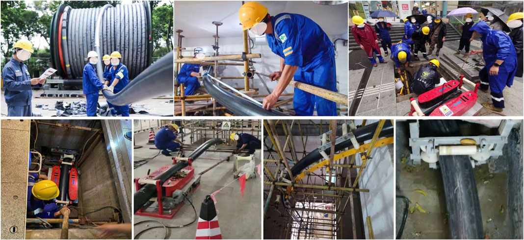
FIGURE 8. The layout operation of HTS cable.
At the same time, the cryogenic cooling subsystem was installed on the second floor of Binhe Substation. We overcame difficulties such as urban area lifting, noise sensitivity, and high humidity to complete the integration. After integration of cable and the cooling subsystem, vacuum leakage and pressure tests were conducted and then the HTS cable cooling process began until the temperature, liquid level, and other operation parameters reached the required values. Once the cooling condition was satisfied, pre-commissioning tests of the HTS cable system were conducted by a third-party institute. The tests mainly concluded AC withstanding voltage test, HTS phase DC current test, and so on. Table 3 gives the pre-commissioning test items and results. Figure 9 shows the pictures of integration and pre-commissioning field test.
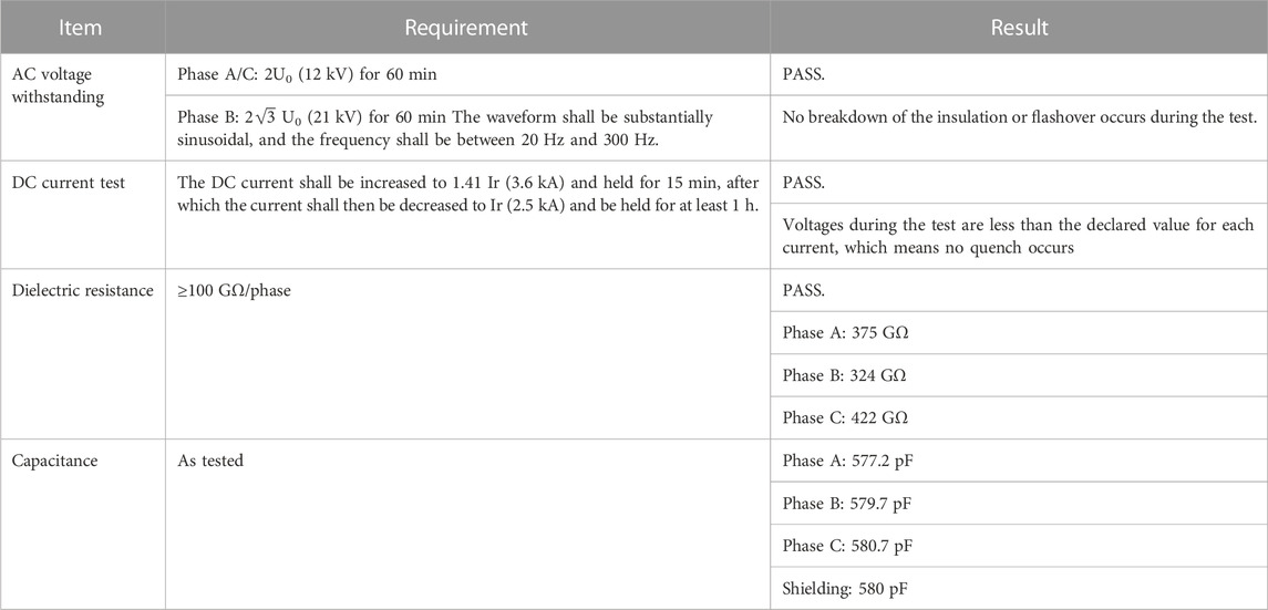
TABLE 3. Mainly pre-commissioning test items of the HTS cable system.

FIGURE 9. Integration and pre-commissioning field test.
On 28 September 2021, the demonstration project was successfully put into operation to supply power to Ping’an Building, the tallest building in the Greater Bay Area, China. After the operation, we continued to conduct several tests on the reliability and maintainability of the cryogenic cooling system. The tests included cold head hot plug, backup cooling system quick cut-in, and LN2 pumps switching.
3 Conclusion and outlook
Shenzhen Power Supply launched a HTS cable demonstration project in urban distribution network in 2016. Five years on, a 400 m/10 kV/2.5 kA concentric HTS cable system was energized and began to supply power for Ping’an Financial Centre, Shenzhen’s landmark building since 28 September 2021. Shenzhen’s HTS cable was the first one using YBCO tapes, and it was also the world’s first superconducting power cable applied to the center area of a megacity. This paper systematically reviews the design, test, construction, and demonstration details of the Shenzhen cable system.
In our R&DD practice, we have solved several key technical problems of HTS cable in system design, manufacturing, test, layout, integration, operation, and maintenance. Meanwhile, we also identified some hinders factors that need to be addressed to advance the large-scale application. The main issues are cost, long-term reliability, and operational simplicity.
The high cost of HTS cable systems has been the most painful point. The improvement of overall economics of the HTS cable system largely depends on the maturity of the technology and the reduction cost of key materials (such as HTS tapes). As there are fewer terminal users, large scale production and industry competition landscapes have not yet been formed, which is a cause of high manufacturing and construction costs.
System reliability and long-term operation issues should be considered comprehensively. HTS cables running on the real grid are bound to face problems such as short-circuit faults and cryogenic system failures. At present, due to the lack of data on the operation and maintenance, no convincing and widely recognized operating procedures have been developed. The method of all-weather monitoring of the whole HTS power cable system is not yet available, and the codes of long-term reliability need to be addressed.
And simplification of the interface of HTS cable systems is another crucial work. The most remarkable point is that HTS cable systems introduce components that do not exist in conventional ones, such as cryogenic systems. In addition, the non-linear response of superconductors to temperature, pressure, current and etc. makes the protection and control logic of HTS cable systems more complex. How to encapsulate the underlying complex logic, make the operation of HTS cable systems as simple as running conventional cables, and reduce the learning costs for operation and maintenance personnel, is essential for the promotion of HTS transmission systems.
Data availability statement
The raw data supporting the conclusion of this article will be made available by the authors, without undue reservation.
Author contributions
ST, ML, and HX contributed to conception and design of the study. PY and ZzW performed the system analysis. BW, ZW, ZL, and TC wrote the first draft of the manuscript. All authors contributed to manuscript revision, read, and approved the submitted version.
Funding
This research was funded by China Southern Grid, under the Major Science and Technology Program, grant number 090000KK52170171.
Conflict of interest
ST, ML, HX, ZzW, PY, ZL, ZW, and TC were employed by China Southern Grid Co., Ltd.
The remaining author declares that the research was conducted in the absence of any commercial or financial relationships that could be construed as a potential conflict of interest.
Publisher’s note
All claims expressed in this article are solely those of the authors and do not necessarily represent those of their affiliated organizations, or those of the publisher, the editors and the reviewers. Any product that may be evaluated in this article, or claim that may be made by its manufacturer, is not guaranteed or endorsed by the publisher.
References
Buchholz, A., Noe, M., Kottonau, D., Shabagin, E., and Weil, M. (2021). Environmental life-cycle assessment of a 10 kV high-temperature superconducting cable system for energy distribution. IEEE Trans. Appl. Supercond. 31, 1–5. doi:10.1109/TASC.2021.3070703
Chen, R.-L., Henzler, G. W., Royal, J. H., and Billingham, J. F. (2010). “Reliability test of A 1 kW pulse tube cryocooler for HTS cable application,” in Advances in cryogenic engineering (Melville: Amer Inst Physics), Vols 55a and 55b, 727–735. doi:10.1063/1.3422424
Chikumoto, N., Watanabe, H., Ivanov, Y. V., Takano, H., Yamaguchi, S., Ishiyama, K., et al. (2018). Second cooling test of 1000-m superconducting DC cable system in ishikari. IEEE Trans. Appl. Supercond. 28, 1–5. doi:10.1109/TASC.2018.2815715
Demko, J. A., Nielsen, C., Sauers, I., James, D., Gouge, M., Lindsay, D., et al. (2007). Triaxial HTS cable for the AEP Bixby project. IEEE Trans. Appl. Supercond. 17, 2047–2050. doi:10.1109/TASC.2007.897842
Doukas, D. I. (2019). Superconducting transmission systems: Review, classification, and technology readiness assessment. IEEE Trans. Appl. Supercond. 29, 1–5. doi:10.1109/TASC.2019.2895395
Gouge, M. J., Demko, J. A., Roden, M. L., Maguire, J. F., Weber, C. S., Weisend, J. G., et al. (2008). Vacuum-insulated, flexible cryostats for long HTS cables: Requirements, status and prospects. AIP Conf. Proc. 985, 1343–1350. doi:10.1063/1.2908492
Ha, S.-K., Kim, S.-K., Kim, J.-G., Park, M., Yu, I.-K., Lee, S., et al. (2013). Development of an impedance matching Program for balancing the current distribution in a tri-axial HTS power cable. J. Supercond. Nov. Magn. 26, 759–762. doi:10.1007/s10948-012-2012-4
Hajiri, G., Berger, K., Dorget, R., Lévêque, J., and Caron, H. (2022). Design and modelling tools for DC HTS cables for the future railway network in France. Supercond. Sci. Technol. 35, 024003. doi:10.1088/1361-6668/ac43c7
Honjo, S., Mimura, T., Kitoh, Y., Noguchi, Y., Masuda, T., Yumura, H., et al. (2011). Status of superconducting cable demonstration project in Japan. IEEE Trans. Appl. Supercond. 21, 967–971. doi:10.1109/TASC.2010.2092744
Lee, S. J., Park, M., Yu, I.-K., Won, Y., Kwak, Y., and Lee, C. (2018). Recent status and progress on HTS cables for AC and DC power transmission in Korea. Ieee Trans. Appl. Supercond. 28, 1–5. doi:10.1109/TASC.2018.2820721
Miyagi, D., Sakakibara, R., Shinozaki, Y., Tsuda, M., and Hamajima, T. (2018). Suitable cable structure of HTS triaxial cable cooled by counter flow cooling method for long-distance power transmission. IEEE Trans. Appl. Supercond. 28, 1–5. doi:10.1109/TASC.2018.2810296
Ostergaard, J., and Tonnesen, O. (2002). Results from the Danish high temperature superconducting power cable project. TEION KOGAKU J. Cryog. Supercond. Soc. Jpn. 37, 450–456. doi:10.2221/jcsj.37.450
Rasmussen, C. N., and Rasmussen, C. (1999). Optimization of termination for a high-temperature superconducting cable with a room temperature dielectric design. IEEE Trans. Appl. Supercond. 9, 45–49. doi:10.1109/77.763253
Stemmle, M., Merschel, F., Noe, M., and Hobl, A. (2013). “Ampacity project — worldwide first superconducting cable and fault current limiter installation in a German city center,” in 22nd international conference and exhibition on electricity distribution (CIRED 2013). Presented at the 22nd international conference and exhibition on electricity distribution (CIRED 2013), 1–4. doi:10.1049/cp.2013.0905
Thomas, H., Marian, A., Chervyakov, A., Stückrad, S., Salmieri, D., and Rubbia, C. (2016). Superconducting transmission lines – sustainable electric energy transfer with higher public acceptance? Renew. Sustain. Energy Rev. 55, 59–72. doi:10.1016/j.rser.2015.10.041
Ueda, K., Tsukamoto, O., Nagaya, S., Kimura, H., and Akita, S. (2003). R&D of a 500 m superconducting cable in Japan. IEEE Trans. Appl. Supercond. 13, 1946–1951. doi:10.1109/TASC.2003.812973
Wang, B., Wu, X., Xie, H., Lv, Z., Wang, Z., Song, M., et al. (2021). Design, manufacture, and test of a 30 m 10 kV/2.5 kA concentric HTS cable prototype for urban grid. IEEE Access 9, 120066–120077. doi:10.1109/ACCESS.2021.3108199
Xu, Y., Ma, T., and Dai, S. (2022). Research on impedance balance design and optimization of triaxial HTS cable. J. Supercond. Nov. Magn. 35, 1413–1419. doi:10.1007/s10948-022-06279-5
Keywords: superconducting cable, concentric type, demonstration project, system design, technical review
Citation: Tang S, Li M, Xie H, Wang Z, Yu P, Li Z, Wang Z, Chen T and Wang B (2023) Development and demonstration of concentric-type HTS power cable for distribution grid in Shenzhen urban. Front. Energy Effic. 1:1160372. doi: 10.3389/fenef.2023.1160372
Received: 07 February 2023; Accepted: 23 March 2023;
Published: 30 March 2023.
Edited by:
Miltos Alamaniotis, University of Texas at San Antonio, United StatesReviewed by:
Bin Wang, University of Texas at San Antonio, United StatesKoti Reddy B, Department of Atomic Energy, India
Dimitrios Bargiotas, University of Thessaly, Greece
Copyright © 2023 Tang, Li, Xie, Wang, Yu, Li, Wang, Chen and Wang. This is an open-access article distributed under the terms of the Creative Commons Attribution License (CC BY). The use, distribution or reproduction in other forums is permitted, provided the original author(s) and the copyright owner(s) are credited and that the original publication in this journal is cited, in accordance with accepted academic practice. No use, distribution or reproduction is permitted which does not comply with these terms.
*Correspondence: Bangzhu Wang, Ynp3YW5nQGJqdHUuZWR1LmNu