- Department of Applied Mathematics and Cyber Security, Vasyl’ Stus Donetsk National University, Vinnitsa, Ukraine
Open stubs in a strip (microstrip) transmission line are one of the most common elements of planar circuits used in numerous devices in the various types of wireless systems. Therefore, the urgent problem is to develop an analyzing method for discontinuities in the form of the open stub in a microstrip transmission line at frequencies at which the high-frequency effects must be considered. In the paper, a technique of scattering characteristics calculating on a symmetrical microstrip open stub by transverse resonance method is presented. Boundary value problems for a rectangular volume resonator based on a microstrip transmission line with a symmetric open stub are solved for the three options boundary conditions in the symmetry plane and on the longitudinal boundaries. The intersection of the spectral curves obtained by the numerical solution of the “electric” and “magnetic” boundary value problems determines the minima of a reflection or transmission coefficients of fundamental wave on discontinuities. To algebraize the boundary value problems for the eigen frequencies of volume resonator with discontinuity, the corresponding two-dimensional functions of the magnetic potential are constructed, through which the components of the current density on the strip are determined. The functions of magnetic potential were defined by decomposing them into expansion by Fourier series, which ensures stable convergence of the series and numerical calculation algorithm. The developed technique has been tested by calculating the eigenfrequency spectra of an open microstrip stub using the transverse resonance method on the example of an open stub in a microstrip transmission line with a resonant frequency of about 3.0 GHz. Also, a technique for numerical solutions of “electric” and “magnetic” boundary-value problems for resonators with two electrodynamically coupled symmetric open stubs in a microstrip transmission line is developed.
1 Introduction
Open or short-circuit stubs in a strip (microstrip) transmission line are one of the most common elements of planar circuits used in numerous devices in the microwave frequency range: various types of filters, couplers, power amplifiers, antennas, sensors, wireless energy transfer systems, etc. Modern planar circuits in the microwave frequency range already contain stubs of a complex shape and a complex pattern inside the microstrip line (Yang et al., 2022; Martín et al., 2003; Boutejdar et al., 2009; MezaalY et al., 2018; Fan et al., 2018; Deshmukh et al., 2012; Deb Roy et al., 2018; Henderson et al., 2018).
The scattering characteristics of ordinary rectangular stubs in a microstrip line are easily determined by transmission line theory by which calculates the input admittance of the stub. A more accurate analysis of such discontinuity, which considers edge and other effects of a microwave circuit with an open or shorted stub, is already a difficult problem of applied electrodynamics. Given the computing capabilities of modern computer technology, complex planar circuits are analyzed using commercial programs by numerical methods, mostly by the moment’s method followed by the construction of an equivalent discontinuity circuit. Rigorous analysis of stub discontinuities in strip and microstrip lines can be carried out using the mode matching method, which is based on the decomposition method and describes the field in them by the eigenwaves of each partial region. But that is a cumbersome method.
More promising for rigorous analysis of such discontinuities, in our opinion, is the transverse resonance method, which was introduced by Sorrentino and Itoh (Sorrentino, 1989) and allows analyzing complex structures without breaking the microwave circuit into small elements. The idea of the method is that there is a relationship between the eigenfrequencies of the volume resonator, in which the discontinuity is located, and the scattering matrix elements on this discontinuity. The transverse resonance method is a universal method for analyzing waveguide and planar circuits, which calculates both the dispersion characteristics of regular transmission lines and the scattering characteristics of unregular distributed circuits (Uwano et al., 1987; Alessandri et al., 1992; Bornemann, 1991; Schwab and Menzel, 1992; Tao, 1992; Green, 1989; Barlabe et al., 2000; Varela and Esteban, 2011). Using the example of the periodic structures scattering characteristics (Rassokhina and Krizhanovski, 2009), it was shown that for symmetrical in the transverse direction discontinuities, the intersection points of the eigenfrequency spectra obtained from the solutions of boundary value problems with two different conditions in the symmetry plane directly indicate the zeros or poles of the scattering characteristics. We are talking about the conditions of the electric and magnetic walls (e.w. and m. w.) in the symmetry plane and on the longitudinal boundaries of the resonator, according to which the boundary value problems with such boundary conditions are called “electric” and “magnetic” boundary value problems, respectively (Rassokhina and Krizhanovski, 2018).
The aim of the study is to develop a technique of algebraization of boundary value problems for the analysis of distributed discontinuity in the form of a symmetric open stub in a microstrip transmission line by the transverse resonance method.
2 Formulation and solution of boundary value problems
The topology of the two-layer planar structure under consideration is provided in Figure 1, which shows a symmetrical open stub in a microstrip transmission line. According to the transverse resonance method, to determine the resonant interaction frequencies of the fed transmission line 1 with discontinuity 2-3, the two boundary value problems with electric and magnetic wall conditions (e.w. or m. w.) in the plane of symmetry
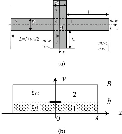
Figure 1. (A) Topology of a symmetrical open stub in a microstrip line, top view, and (B) cross section of volume resonator with a microstrip line.
Consider the solution of the boundary value problem for the current density
where
The electromagnetic field components in the shielded structure satisfy the Helmholtz equation in Cartesian coordinates. The current density distribution function in the microstrip line is determined by the difference of the magnetic field’s tangent components and therefore also satisfies the Helholtz equation.
Polynomial solutions of the Helmholtz equation were studied in (Burskii and Buryachenko, 2013) as dual problem for high-order hyperbolic problems in elliptic planar domains. For simple discontinuities such as microstrip step discontinuity, the function can be constructed as a series of orthogonal polynomials (Rassokhina and Krizhanovski, 2018; 2023). For a more complex topology to avoid the cumbersome calculations, the current density distribution function in partial regions should be described in the form of Fourier series.
The current density distribution function for a strip line with an open stub satisfies the Helmholtz equation:
when
Considering the above, the two-dimensional function for the magnetic potential
for
for
for
for
From the continuity conditions of the functions on the partial domains boundaries, a system of linear algebraic equations (SLAE) is obtained in the form:
Equating the determinant of SLAE Equation 3 to zero, we obtain a spectrum of eigenvalues
The expansion coefficients
It is worth noting that the “electrical” boundary value problem also has a solution by
For the “electric-magnetic” boundary value problem under the condition of a magnetic wall in the symmetry plane
where
where, by analogy with the “electrical” boundary problem,
In the same way, the two-dimensional function of the magnetic potential is defined for the boundary value problem with boundary conditions of the magnetic wall in the plane of symmetry and on the longitudinal boundary of the volume resonator (“magnetic” boundary problem).
The boundary value problems solving for current density eigenfunctions in an irregular microstrip line is used for solving of boundary problem for rectangular volume resonators with this discontinuity. In this case, the discontinuity is an open symmetric stub in the microstrip transmission line.
According to the transverse resonance method, the points of spectral curves intersection, corresponding to the solutions of the electric and magnetic–electric boundary value problem, determine the minimum transmission coefficient points (Rassokhina and Krizhanovski, 2009). And the points of spectral curves intersection, corresponding to the solutions of the electric and magnetic boundary value problem, determine the minimum reflection coefficient points.
The Helmholtz equation and boundary conditions for an electric
where
The electric and magnetic vector potentials of a rectangular volume resonator are presented in the form of double Fourier series:
where
when
The coupling integrals
where
The SLAE for the eigenfrequencies of a three-dimensional resonator is as follows:
where
From the condition that the determinant of system Equation 7 of equations is zero, we obtain the eigenfrequencies
3 Algorithm testing and results of symmetric open stub analysis
The algorithms were developed and tested on the example of a two-dimensional planar structure on a Ro3010 laminate with a thickness of
Numerical calculations have shown that using trigonometric basis in the expansion of the current density distribution function provided uniform convergence of the algorithms for calculating eigenvalues and, accordingly, eigenfunctions
Eigenvalues of a strip resonator with a symmetric open stub of length
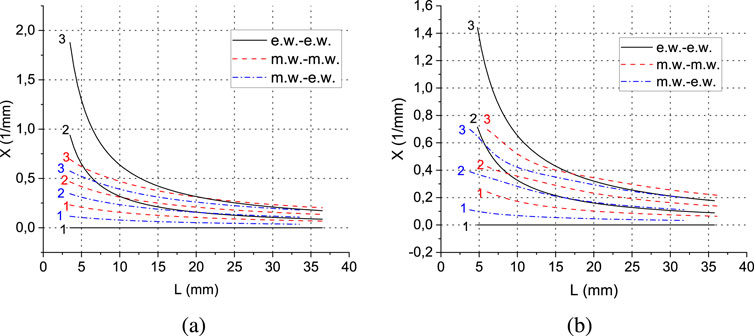
Figure 2. The first three eigenvalues
According to the approximation of the transmission lines theory, the input conductivity of a symmetrical open stub is equal to:
where
For an MSI personal computer with an Intel(R) Core(TM) i3 CPU 2.13 GHz processor, the time to calculate the one points for one root of the characteristic Equation 7 by accuracy
Figure 3A shows the spectra of the resonator’s eigenfrequencies obtained from solutions of three boundary value problems for a volume resonator with discontinuity in the form of a symmetric open stub in a microstrip transmission line. The intersection point of the spectral curves of the “electric” and “magnetic-electric” boundary value problems corresponds to the frequency at which the minimum of the transmission coefficient is observed
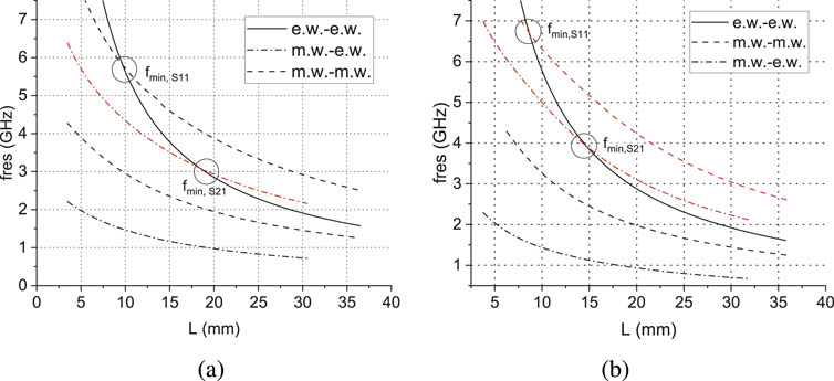
Figure 3. Spectrum of eigenfrequencies of a three-dimensional rectangular resonator based on an microstrip line with a symmetrical open stub, obtained from the solutions of boundary value problems with parameters (in mm): (A)
Figure 3B shows the spectra of the resonator’s eigenfrequencies with a stub width
The results of the scattering characteristics calculations were verified using the microwave design software. The values of the frequencies of resonance interaction obtained from the eigenfrequency spectra and full-wave electrodynamic modeling are almost in agreement.
Thus, according to the results of numerical calculation, a physically correct result was obtained for the scattering characteristics on a symmetrical stub in a microstrip transmission line, considering high-frequency effects, namely, dispersion and marginal capacitance of the open stub.
In Figure 4 the dependence of the resonance frequency on the stub width is shown. As expected from physical considerations, the frequency of resonance reflection increases with the ratio
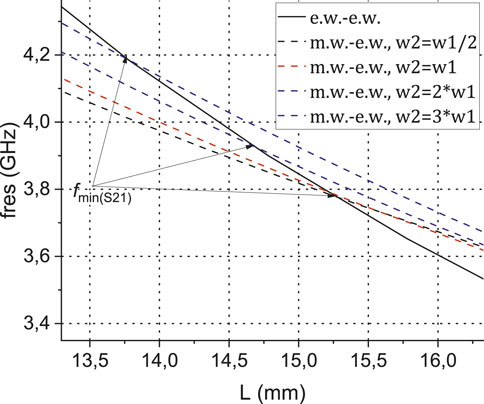
Figure 4. Frequency shift of the of eigen frequencies spectrum of a volume resonator with a symmetric open stub in microstrip line depending on the stub width
4 Electromagnetically coupled open microstrip stubs
Electromagnetically coupled discontinuities in planar circuits can also be analyzed by the transverse resonance method. For this purpose, the planar scheme is symmetrized and two boundary value problems are solved under the conditions of an “electric” and “magnetic” wall in the symmetry plane.
The analyzed structure is shown in Figure 5. The plane of symmetry is located at
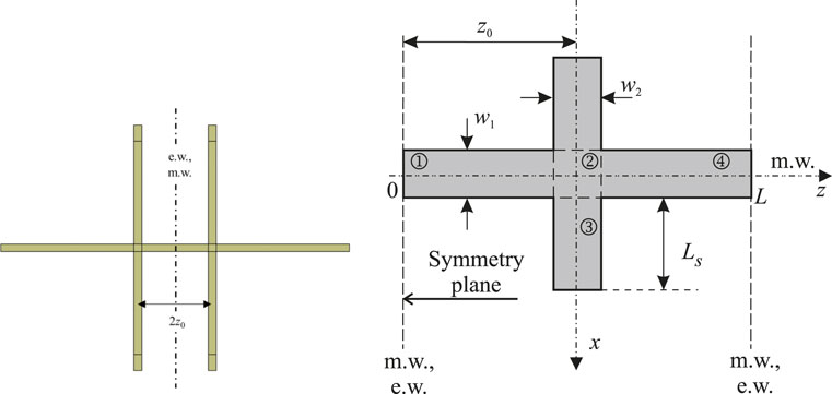
Figure 5. The coupled microstrip stubs: principal scheme of analyzing structure and their decomposition in partial regions.
For the “electrical” boundary value problem, the expressions for the current density potential are as follows:
where
where
From the continuity conditions of the basis function and its derivatives at the partial regions boundaries, a homogeneous SLAE is obtained, the condition for the solution of which is the equality of its determinant to zero, from which the spectrum of eigenvalues
The coupling integrals with the basic functions of volume resonance are calculated according by Equation 6.
For the “magnetic” boundary value problem, only the expressions for the current density potentials in partial regions 1 and 4 are changed:
The results of calculations of eigen frequencies of the resonator, obtained from the solution of the “electric” and “magnetic” boundary value problem, are shown in Figure 6, where the spectrum of eigen frequencies for two different distances values
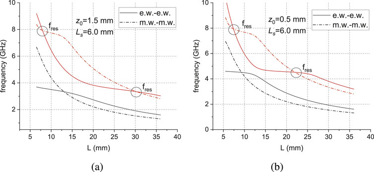
Figure 6. Spectrum of eigenfrequencies of a volume resonator based on an microstrip line with two coupled symmetrical open stubs, obtained from the solutions of boundary value problems with parameters (in mm):
Figures 7A, B also shows the spectrum of eigen frequencies of a planar structure with two coupled symmetrical stubs of width
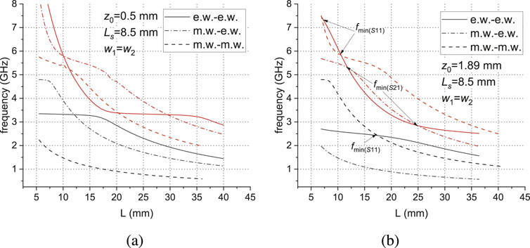
Figure 7. Spectrum of a volume resonator eigenfrequencies based on an microstrip line with two coupled symmetrical open stubs, obtained from the solutions of three boundary value problems with parameters (in mm):
Thus, the resonator’s spectral characteristics with discontinuity fully determine the frequencies of resonant interaction of microstrip stubs with the main transmission line.
5 Conclusion
A method of an open stubs analyzing, single and electrodynamically coupled, in a microstrip transmission line by the transverse resonance technique is proposed. To implement the method, the boundary problems for the eigenfunctions of the strip resonator’s current density with a symmetrical open stub were previously solved under the condition of an electric and magnetic wall in the symmetry plane and at the longitudinal boundary. To determine the eigenfunctions of the current density, the trigonometric basis was used, which ensures fast and uniform convergence of numerical calculation algorithms for the eigenfunctions. The use of the trigonometric basis led to the uniform and stable convergence of the algorithm for numerical calculation of the eigen frequency spectrum of a volume cavity with a discontinuity in it.
From the study of the eigenfrequency spectra of volume resonators containing a planar circuit calculated under two different conditions in the symmetry plane, preliminary information about the frequencies of resonant interaction of the discontinuity with the fed microstrip transmission line is obtained. The developed technique of algebraization of boundary value problems for a microstrip line with discontinuity can be applied to the analysis of more complex topologies of microstrip stubs, multi-plane discontinuities and the development of various devices in the microwave frequency range.
Data availability statement
The original contributions presented in the study are included in the article/supplementary material, further inquiries can be directed to the corresponding author.
Author contributions
YR: Writing–original draft, Conceptualization, Investigation, Methodology, Visualization, Software. VK: Writing–review and editing, Conceptualization, Formal Analysis, Investigation, Methodology, Supervision, Validation.
Funding
The author(s) declare that financial support was received for the research, authorship, and/or publication of this article.
Acknowledgments
This research was supported by the project of Volkswagen Foundation” From modelling and analysis to approximation” (2020–2023).
Conflict of interest
The authors declare that the research was conducted in the absence of any commercial or financial relationships that could be construed as a potential conflict of interest.
Publisher’s note
All claims expressed in this article are solely those of the authors and do not necessarily represent those of their affiliated organizations, or those of the publisher, the editors and the reviewers. Any product that may be evaluated in this article, or claim that may be made by its manufacturer, is not guaranteed or endorsed by the publisher.
References
Alessandri, F., Baini, G., D’Inzeo, G., and Sorrentino, R. (1992). Conductor loss computation in multiconductor mic’s by transverse resonance technique and modified perturbational method. IEEE Microw. Guid. Wave Lett. 2, 250–252. doi:10.1109/75.136522
Barlabe, A., Comeron, A., and Pradell, L. (2000). Generalized transverse resonance analysis of planar discontinuities considering the edge effect. IEEE Microw. Guid. Wave Lett. 10, 517–519. doi:10.1109/75.895088
Bornemann, J. (1991). A scattering-type transverse resonance technique for the calculation of (m) mic transmission line characteristics. IEEE Trans. Microw. Theory Tech. 39, 2083–2088. doi:10.1109/22.106550
Boutejdar, A., Omar, A., Batmanov, A., and Burte, E. (2009). Design of compact low-pass filter with with wide rejection band using cascaded arrowhead-dgs and multilayer-technique, in 2009 German microwave conference (IEEE), 1–4. doi:10.1109/gemic.2009.4815903
Burskii, V. P., and Buryachenko, K. A. (2013). On the breakdown of the uniqueness of a solution of the dirichlet problem for typeless differential equations of arbitrary even order in a disk. J. Math. Sci. 190, 539–566. doi:10.1007/s10958-013-1270-4
Deb Roy, S., Batabyal, S., Chakraborty, S., Chakraborty, M., and Bhattacharjee, A. K. (2018). “Control of higher order modes and their radiation in microstrip antenna using extremely compact defected ground structure symmetric stub,” in 2018 2nd international conference on electronics, materials engineering amp; nano-technology (IEMENTech) (IEEE), 1–5. doi:10.1109/iementech.2018.8465287
Deshmukh, A., S, S., and Ray, K. (2012). “Analysis of stub loaded circular microstrip antennas,” in 2012 international conference on advances in computing and communications (IEEE), 282–285. doi:10.1109/icacc.2012.65
Fan, L., Qian, H. J., Yangl, B., Wang, G., and Luo, X. (2018). Filtering power divider with wide stopband using open-stub loaded coupled-line and hybrid microstrip t-stub/dgs cell, in 2018 IEEE/MTT-S international microwave symposium - ims, 1–4. doi:10.1109/mwsym.2018.8439433
Green, H. (1989). Determination of the cutoff of the first higher order mode in a coaxial line by the transverse resonance technique. IEEE Trans. Microw. Theory Tech. 37, 1652–1653. doi:10.1109/22.41018
Henderson, K. Q., Latif, S. I., Lazarou, G., Sharma, S. K., Tabbal, A., and Saial, S. (2018). Dual-stub loaded microstrip line-fed multi-slot printed antenna for l te bands, in 2018 IEEE international Symposium on Antennas and Propagation amp; USNC/URSI national radio science meeting, 1743–1744. doi:10.1109/apusncursinrsm.2018.8608453
Martín, F., Falcone, F., Bonache, J., Lopetegi, T., Laso, M. A. G., and Sorolla, M. (2003). New cpw low-pass filter based on a slow wave structure. Microw. Opt. Technol. Lett. 38, 190–193. doi:10.1002/mop.11011
Mezaal, Y., S., Hashim, S., A., Al-fatlawi, H., and Hussein, A. (2018). New microstrip diplexer for recent wireless applications. Int. J. Eng. amp; Technol. 7, 96. doi:10.14419/ijet.v7i3.4.16754
Rassokhina, Y., and Krizhanovski, V. (2009). Periodic structure on the slot resonators in microstrip transmission line. IEEE Trans. Microw. Theory Tech. 57, 1694–1699. doi:10.1109/tmtt.2009.2022814
Rassokhina, Y. V., and Krizhanovski, V. G. (2018). The microstrop line step discontinuity analysis by transverse resonance technique: method of boundary value problem algebraization, in 2018 14th international Conference on advanced Trends in radioelecrtronics, Telecommunications and computer engineering (TCSET), 632–636. doi:10.1109/tcset.2018.8336281
Rassokhina, Y. V., and Krizhanovski, V. G. (2023). Transverse resonance technique for analysis of symmetrical stub in microstrip transmission line. Visnyk NTUU KPI Seriia - Radiotekhnika Radioaparatobuduvannia 92, 5–11. doi:10.20535/RADAP.2023.92.5-11
Schwab, W., and Menzel, W. (1992). On the design of planar microwave components using multilayer structures. IEEE Trans. Microw. Theory Tech. 40, 67–72. doi:10.1109/22.108324
Sorrentino, R. (1989). Numerical techniques for microwave and millimeter-wave passive structures, ch. 1L. Wiley, New York, 637–693. chap. Transverse Resonance Technique.
Tao, J.-W. (1992). A modified transverse resonance method for the analysis of multilayered, multiconductor quasiplanar structures with finite conductor thickness and mounting grooves. IEEE Trans. Microw. Theory Tech. 40, 1966–1970. doi:10.1109/22.159636
Uwano, T., Sorrentino, R., and Itoh, T. (1987). Characterization of strip line crossing by transverse resonance analysis. IEEE Trans. Microw. Theory Tech. 35, 1369–1376. doi:10.1109/tmtt.1987.1133862
Varela, J. E., and Esteban, J. (2011). Analysis of laterally open periodic waveguides by means of a generalized transverse resonance approach. IEEE Trans. Microw. Theory Tech. 59, 816–826. doi:10.1109/tmtt.2011.2111379
Keywords: the helmholtz equation, a boundary value problem, transverse resonance method, resonance frequencies, microstrip line, open stub
Citation: Rassokhina YV and Krizhanovski VG (2024) Transverse resonance technique for analysis of a symmetrical open stub in a microstrip transmission line. Front. Electron. 5:1459220. doi: 10.3389/felec.2024.1459220
Received: 11 July 2024; Accepted: 05 September 2024;
Published: 18 September 2024.
Edited by:
Kateryna Buryachenko, Humboldt University of Berlin, GermanyReviewed by:
Alexander Trubin, Kyiv Polytechnic Institute, UkraineDmytro Hretskykh, Kharkiv National University of Radioelectronics, Ukraine
Piotr Kowalczyk, Gdansk University of Technology, Poland
Copyright © 2024 Rassokhina and Krizhanovski. This is an open-access article distributed under the terms of the Creative Commons Attribution License (CC BY). The use, distribution or reproduction in other forums is permitted, provided the original author(s) and the copyright owner(s) are credited and that the original publication in this journal is cited, in accordance with accepted academic practice. No use, distribution or reproduction is permitted which does not comply with these terms.
*Correspondence: Yulia V. Rassokhina, eXUucmFzc29raGluYUBkb25udS5lZHUudWE=
 Yulia V. Rassokhina
 Vladimir G. Krizhanovski