 Wei Sun1,2
 Chengao Lu
- 1College of Water Conservancy and Hydropower Engineering, Hohai University, Nanjing, China
- 2Guiyang Engineering Corporation Limited, Guiyang, China
Tipping is characterized by the continuous rotation of blocks. The tipping deformations of high and steep hard rock slopes and steeply inclined layered slopes reveal that, under high in situ stress conditions, the formation process of high and steep slopes involves a strong release of horizontal stress. Depending on the specific geological conditions of the slope, additional loads may be provided to the block rotation deformation through traction or push mechanisms, causing slopes that do not originally meet the tipping conditions to exhibit tipping deformations. For hard rock tipping, the load level must be sufficient to cause the rock blocks to fracture and overcome the constraints of their own strength on rotational deformation, allowing the blocks to continue rotating. Thus, hard rock tipping involves two types of mechanical behaviors: macroscopic discontinuous deformation of the block boundaries and the continuous-discontinuous mesoscopic fracturing of the blocks themselves. Analytical solutions are no longer suitable for analyzing hard rock tipping deformation problems, necessitating the use of macroscopic-mesoscopic numerical methods that can simultaneously simulate discontinuous deformation of structural planes and rock block fracturing, such as UDEC-Voronoi simulation techniques. After analysis, it is necessary to meet two conditions: 1. To form an external load that can cause the rock to rotate continuously beyond its own weight; 2. The slope forms large structural planes on the steep slope, and the vertices of these structural planes have steep joints. The flexible use of UDC-Voronoi method improves the simulation accuracy and calculation efficiency.
1 Introduction
Based on the basic composition of engineering rock masses (lithology and structural planes) and their existing conditions (in situ stress), Kaiser and Kim (2008) classified engineering rock mechanics problems into three categories: high-stress failure, structure-controlled problems, and large deformation in soft rock. The first two categories correspond to hard rock conditions, differing in the in situ stress environment of the rock mass. High-stress problems correspond to deeply buried conditions, while structure-controlled problems are most typically represented by gravity-driven slope engineering, followed by shallowly buried, large-span underground chambers. For this reason, in hard rock slope engineering practice, rock block deformation is often overlooked, with the focus primarily on the deformation of structural planes and the instability of blocks under the influence of gravity (Wyllie and Mah, 2017; Hoek and Bray, 1974). Many researchers use various methods to study slope stability analysis, including experimental method, numerical simulation method and zoning method (Cai et al., 2024; Wang et al., 2023; Feng et al., 2011; Melnikov et al., 2004). This fundamental idea has been applied to the study of tipping problems. Even for layered tipping deformations occurring under relatively weak lithological conditions, the focus is often on the geometric relationship between the layers and the slope, as well as the load balance conditions, while ignoring the effects of lithology and in situ stress, with the assumption that the deformation of the layers (structural planes) is the controlling factor (Goodman and Bray, 1977). Miao et al. studied the overload failure mode of slope with weak structural plane (Miao et al., 2024). Gao et al. developed GPG program, which can safely and effectively monitor the structural plane of slope (Gao et al., 2021). Song et al. obtained the deformation characteristics of slope with weak structural plane in development by monitoring the deformation data of slope (Song et al., 2018). Sun et al. summarized the mechanical characteristics of slope with weak structural plane through experiments and predicted its deformation (Sun et al., 2014). Fang et al. simulated the deformation of loess slope with joints and cracks through physical model experiments (Fang et al., 2024). For example, the widely used criteria for layered slope tipping shown in Figure 1 are based on the assumption of self-weight, focusing on the load balance relationship of the blocks. They ignore changes in the stress conditions, deformation, and potential failure of the rock blocks, and do not consider the impact of rock block failure on the load balance relationship of the blocks, still assuming it to be a typical structure-controlled problem.
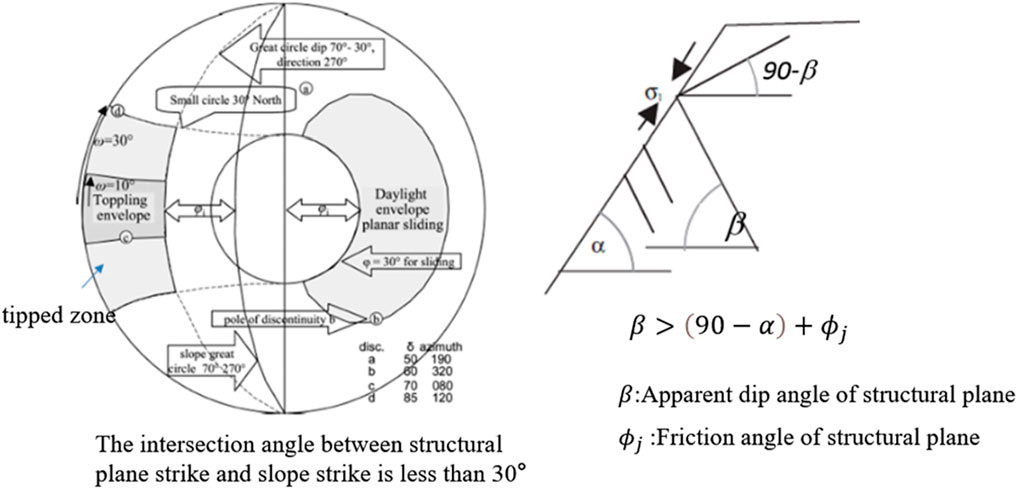
Figure 1. Schematic diagram of the conditions for tipping deformation occurrence (Goodman and Bray, 1977).
The tipping occurrence conditions shown in Figure 1 only consider the self-weight of the blocks, ignoring the interaction of loads between blocks. Therefore, they suggest that tipping occurrence conditions are unrelated to the stress distribution of the slope and are unaffected by the height of the slope. After studying tipping slopes like the hard rock tipping at Guobu in the Laxiwa Gorge (Zhu, 2014) and bedding tipping at Yangqu (Ren et al., 2009), Zhu (2014) argued that assuming only the self-weight of blocks is idealized and lacks quantitative rationality. He believes that the stress redistribution of high and steep slopes significantly changes the stress state of blocks and promotes the occurrence of tipping. Stress and the resulting rock deformation play an important role, and tipping deformation is no longer a purely structural control problem.
To this end, Zhu (2014) adopted a simplified UDEC model. The model simulated a set of reverse steeply inclined dominant structural planes (meeting the tipping conditions shown in Figure 1) and allowed for large strain and large deformation of the blocks under load.
The results shown in Figure 2 reveal the limitations of the tipping criteria shown in Figure 1 when applied to high and steep hard rock slopes. Tipping deformation is not only a structural control problem but also closely related to the stress distribution of the slope (Jiang et al., 2023; Haghgouei et al., 2020; Zhang et al., 2020; Guo et al., 2024; Ma et al., 2024; Zhang and Tang, 2024). When the contour morphology of the slope is fixed, the characteristics of slope stress distribution are closely related to the in situ stress conditions and geological conditions during the slope formation process (Huang et al., 2011).
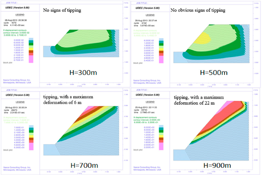
Figure 2. The impact of slope height on triggering tipping deformation (Zhu, 2014).
Therefore, in the actively tectonic Qinghai-Tibet Plateau region, the intense release of horizontal stress during river incision processes is conducive to triggering tipping deformation. In reality, tipping deformations of riverbank slopes in deeply incised valleys of the Qinghai-Tibet Plateau are significantly more common than in other regions (Huang et al., 2022). Some of these occur as bedding tipping outside steeply inclined slopes (Lu et al., 2017), such as the tipping on the left bank of the upstream water level of the Jinping No. 1 Hydropower Station on the Yalong River (Huang, 2007), and the bedding tipping on the left bank of the Yangqu River (Ren et al., 2009). These occurrences do not satisfy the conditions shown in Figure 1 but are closely related to the stress redistribution in high and steep slopes. In reality, hard rock tipping, especially large-scale hard rock tipping, is often closely related to the presence of weak geological conditions in the vicinity of the slope toe. Examples include the tipping deformation of granite diorites in Chuquicamata, Chile (Board et al., 1996), and the tipping deformation of granitic rock slopes in the Laxiwa Gorge of the Yellow River, China (Zhu, 2014). Clearly, the variability in the geological conditions of the slope rock masses allows for various factors that can trigger tipping “external loads.” Figure 3 provides a summary of three such scenarios.
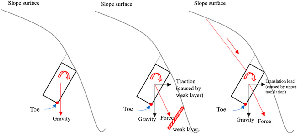
Figure 3. Three conditions for rotational deformation of slope blocks.
Figure 3 (left) represents the tipping occurrence conditions described by the G-B model (Goodman and Bray, 1977): the self-weight of the block is located outside the toe, causing the block to tend to rotate. The tipping analysis software developed by RocScience is based on this assumption, assuming that the block is only subjected to self-weight (Yu et al., 2023; Wang et al., 2024a; Wang et al., 2024b). Figure 3 (center and right) are extensions of this criterion, reflecting the influence of geological conditions on the stress state of the block and the occurrence conditions of tipping.
The Figure 3 (left) and Figure 1 exhibit inherent consistency, primarily derived from the study and summarization of layered tipping slope. The reported instances of hard rock tipping caused by traction, as depicted in Figure 3, are also applicable; examples such as Chuquicamata (Board et al., 1996) and the Laxiwa Gorge slope (Zhu 2014) fall into this category. In comparison, the cases of translational tipping shown in Figure 3 (right) are extremely rare. Ning et al. (2021) proposed a mechanism for translational tipping based on the study of a tipping body along the Lancang River, but this tipping still conforms to the typical characteristics of reverse steeply inclined layered structures composed of slate, as described in Figures 1, 3 (left). The unloading effect during the process of deep incision by the Lancang River in the Qinghai-Tibet Plateau can provide additional loads for the trend of block rotation in the slope, belonging to traction rather than translational action.
During the process of block rotation, there may be “sticking points” around the corners, which inhibit the rotation. Obviously, the tipping of hard rock slopes must overcome the constraint of block strength on the trend of rotation, which implies that the “sticking points” may fracture. Rock fracture becomes one of the important conditions for continuous rotation of the block and the generation of hard rock tipping deformation. Therefore, the study of hard rock tipping cannot only focus on the discontinuous deformation of structural surfaces (sliding, opening, etc.) during block rotation, but also needs to investigate the fracture phenomenon caused by changes in the stress conditions of the block itself. Therefore, hard rock tipping involves the micromechanical behavior of rock fracture, which is beyond the scope of analytical method and needs numerical method. This process needs to address two main issues: firstly, the scale range, which refers to the span between the macro large scale of the slope and the micro small size of rock fracture; secondly, the complexity of mechanics, which refers to the macro discontinuous mechanical deformation of block boundaries and the continuous-discontinuous microscopic changes within the block.
The tipping cases reported so far, whether stratified tipping or hard rock block tipping, have shown the basic characteristic that the deformation extends from the foot of the slope to the top of the slope (commonly known as “from bottom to top”), with the maximum deformation occurring at the front edge of the slope (Cai et al., 2019). The right bank of the Lancang River’s M section, characterized by hard rock and blocky structure, has experienced tipping phenomena. However, the tipping deformation is distributed only locally, appearing intermittently with elevation within the same slope section, lacking the characteristic distribution of “from bottom to top,” which reveals the particularity of the tipping causative conditions of the M right bank slope.
This paper relies on the unique hard rock tipping phenomena on the right bank of M, following an approach that combines geology and mechanics. Firstly, it introduces the geological background of the formation of the valley slope in the M section of the Lancang River and the severe changes in rock mass stress revealed by this background, as well as the significant deformation characteristics of the structural surfaces caused by these changes. Then, based on field examples, it analyzes the occurrence conditions, causative mechanisms, and field manifestations of hard rock translational tipping, clarifying the differences between M hard rock translational tipping and previous understandings of tipping problems. The paper focuses on listing and analyzing the common rock block fracture phenomena in translational tipping bodies, the mechanical significance revealed, and the requirements for numerical simulation methods. The UDEC-Voronoi method is used to simulate the stress changes and fracture phenomena within the rock blocks during the rotation process of hard rock blocks.
2 Background conditions of M slope
2.1 Construction movement and regional background
The M section of the Lancang River is located in the eastern part of the Tethys-Himalayan tectonic domain in the southeastern Qinghai-Tibet Plateau. Since the Quaternary, neotectonic movements have caused intense compression, leading to rapid crustal uplift. Against this geological backdrop, the Lancang River has deeply incised the surface, forming deep gorges and steep slopes. During the formation of these slopes, the stress field of the rock mass underwent significant changes, causing structural surface deformation and block fracturing. Various forms of deformation and damage remain in the shallow layers of the slopes. In other words, the neotectonic processes, the formation of steep slopes, and the intense mechanical responses of the shallow rock masses in the M section of the Lancang River constitute the macro background conditions for the formation of new geological phenomena.
The intense tectonic compression experienced by the M section of the Lancang River since the Quaternary is illustrated in Figure 4. Figure 4 presents the current surface displacement rates in the Qinghai-Tibet Plateau based on GPS monitoring results (Wang et al., 2017), with a solid circle indicating the approximate location of the M section of the Lancang River. The figure shows that the current horizontal surface displacement rate in this area is nearly 15 mm/year, revealing that the M section is still subjected to intense compression from neotectonic movements. Compared to other regions in the world, this area remains one of the most intensely compressed regions currently.
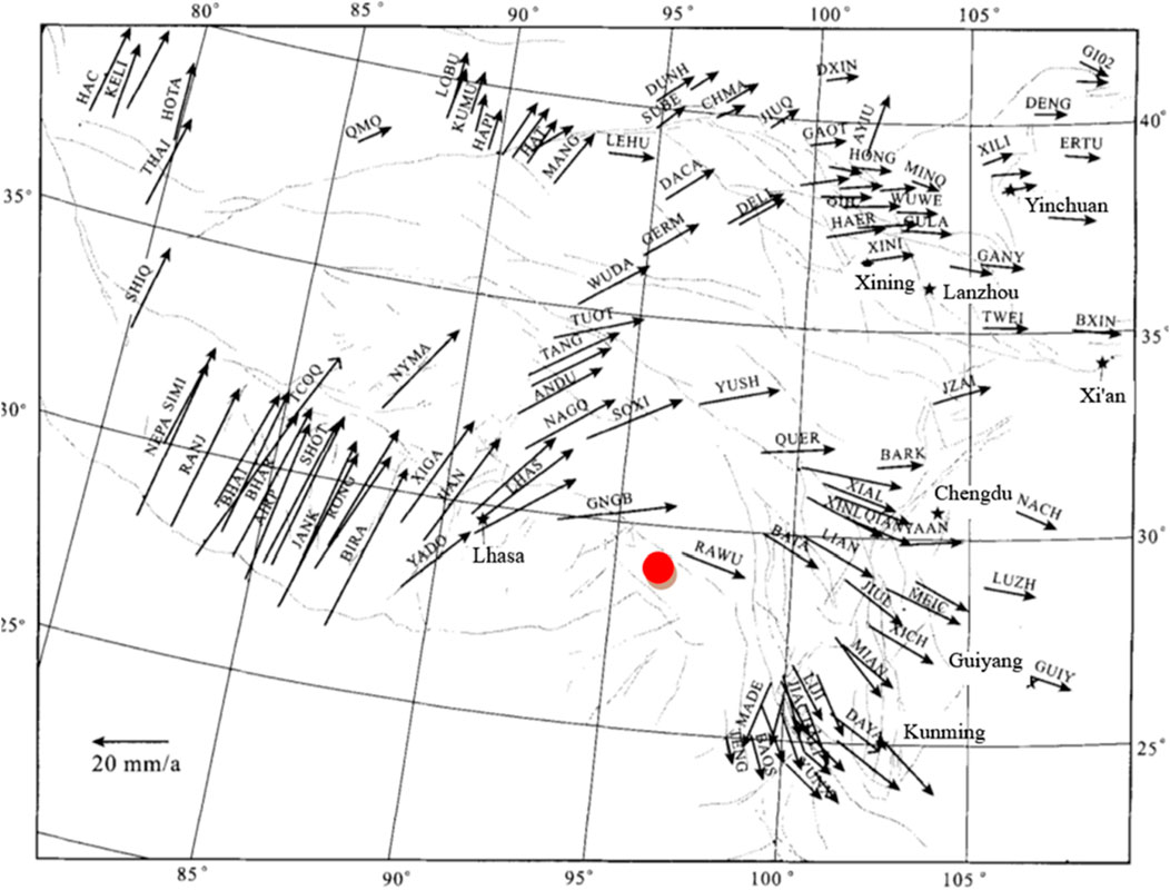
Figure 4. Surface displacement rates of the Qinghai-Tibet plateau based on GPS monitoring results (Wang et al., 2017).
In Figure 4, letters represent cities or displacement observation points, and unclear dashed lines represent mountains. The intense tectonic compression has led to rapid crustal uplift, while river downcutting and erosion in the M section have formed typical V-shaped valleys and steep slopes (Figure 5). The river flows from the west (280°) to the east (20°), forming NWW-NNE oriented valley slopes. The right bank slope of the M section extends from the riverbed (2,600 m) to over 5,000 m, with a natural slope height exceeding 2000 m. Below the elevation of 2,700 m, the slope is 67°, and above 2,700 m, the natural slope gradient is mostly between 35° and 40°. Above the elevation of 2,700 m, multiple gullies develop on the slope, forming alternating ridge landforms. Due to the lack of lateral constraints, the deformation of the ridge rock mass along structural surfaces is more pronounced, with intense superficial relaxation affecting a significant depth.
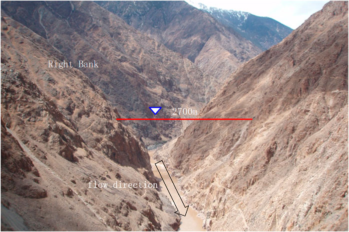
Figure 5. Morphology of the valley bank slope in the M section of the Lancang River.
2.2 Model building and calculation analysis
The M section of the Lancang River is composed of hard dacite and granite, with the uniaxial compressive strength of the rock averaging over 120 MPa under natural conditions. Historical intense tectonic compression has formed multiple sets of structural planes in the rock mass, but large faults are very rare, mainly consisting of joints of varying scales. Five sets of joints have developed on the right bank, with two sets being the most prominent and nearly parallel to the slope direction, located inside and outside the steep slope. The dominant joint set outside the steep slope dips 20°∼30°, with a dip angle of 70°∼90°, while the joint set inside the steep slope dips 200°∼210°, with a dip angle of 70°∼90°. These two sets of joints form a conjugate relationship, and their distribution characteristics vary. In the middle and lower reaches of the M right bank, the outside steep slope joints are relatively developed, while in the middle and upper reaches, the inside steep slope joints are more developed. This results in variations in the deformation phenomena and mechanisms along different ridges of the M river section.
In addition to the two sets of conjugate joints on the outside and inside of the steep slope, two more sets of steep conjugate joints have developed, oriented roughly perpendicular to the riverbank. The gullies on the slope mainly develop along these two sets of joints, providing lateral boundary conditions for the slope deformation. The fifth set of joints is the least developed, dipping upstream and slightly inward, characterized by primary, closed flow layers that appear locally.
Under the compressive tectonic forces, the deep incision of the Lancang River at the M section forms steep slopes. During the geological evolution, stress adjustments within the hard rock slopes induce deformation along structural planes, most evident within approximately 150 m of the slope’s shallow part, and the influence can extend to 400 m or more. Figures 6a,b show the numerical simulation results of right bank deformation during the valley evolution under the conditions where the dip slopes and the reverse dip slopes dominate. UDEC simulation was used to equivalently simulate water erosion in the form of excavation. The numerical model not only simulated the discontinuous deformation (sliding, opening, squeezing, etc.) along the dominant joints of the rock mass but also used built-in strain-softening constitutive models to equivalently simulate potential fracturing of the blocks with plastic large strain. This simulation simplified the timing issues involved in the slope formation process by reducing the slope height. The model only simulated river erosion below an elevation of 3,700 m, not considering the evolution of the upper slope, which to some extent weakened the range of water erosion and aimed to minimize the impact of simulating long-term incision on stress response through instant excavation, in order to achieve better qualitative rationality.
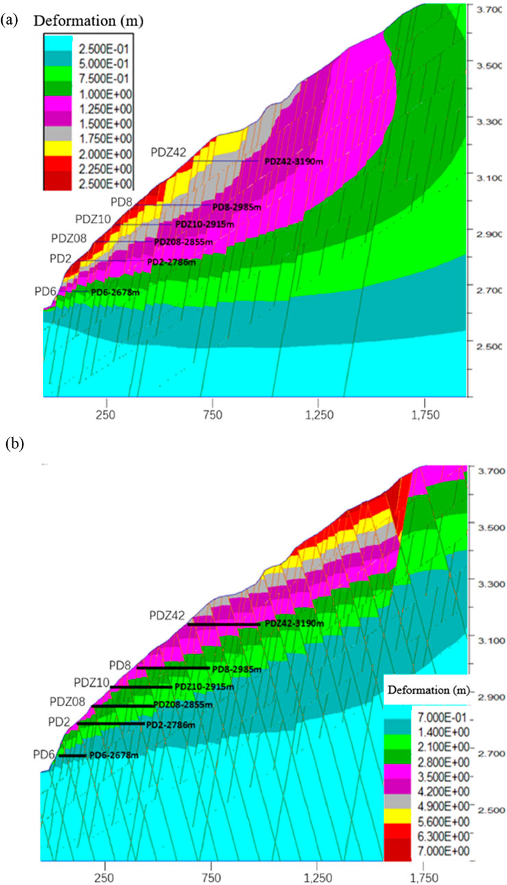
Figure 6. Deformation characteristics of the right bank slope caused by the evolution of the M section valley (Without using UDEC-Voronoi): (a) Only consider the steep and inclined joint group along the slope; (b) The situation where the anti slope steep dip joint group is dominant.

Figure 7. Deformation concept map.
The parameter setting of the model and the parameter table of joint group are shown in Tables 1, 2. The geological information and geographical location information of the slope can be partially found in the Supplementary Material (including the location information of all the pictures appearing in the article).
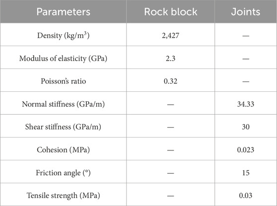
Table 1. UDEC parameter list.
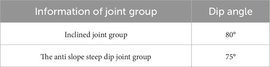
Table 2. Joint group Parameter Table.
The results shown in Figure 6a represent the scenario where the steeply dipping external joint set is dominant, corresponding to the mid-lower reaches of the M section. The UDEC simulation results indicate that slope deformation is most prominent in the elevation range of 2,700∼3,150 m. The deformation contour map reveals that the displacement deformation along the steeply dipping joints is very significant, creating conditions for shear fracturing of the gently dipping external slope (corresponding to the gently dipping boundary in the contour map). The range of deformation is substantial, with the depth of significant deformation during the valley slope evolution process reaching up to 400 m or even deeper within the elevation range of 2,800∼3,150 m.
Figure 6b simulates three sets of joints: steeply dipping with the slope, steeply dipping against the slope, and gently dipping within the slope. In this case, the steeply dipping against the slope joints are dominant. The UDEC simulation results show a deformation range similar to Figure 6a, but the deformation mode differs. Here, the deformation trend is controlled by the dominant steeply dipping against the slope joints. However, the connectivity rate of these joints in the calculation model is set at 100%, overestimating the likelihood of tipping. Additionally, the spacing of this set of joints is constant, differing from the heterogeneity in reality, thus overestimating the distribution range of “top-to-bottom” tipping deformation.
The deformation characteristics revealed in Figures 6a,b can be confirmed by the structural dislocation phenomena revealed by the adits arranged within the slope. Firstly, the deformation range and magnitude: the adit located at an elevation of 3,084 m on the ridge upstream of the M section shows intense dislocation deformation even at a depth of 385 m (see Figure 9), consistent with the numerical simulation results. Secondly, the deformation range varies with elevation. This can be seen from the pseudo-fault phenomena (structures formed by intense dislocation along joints) and their distribution characteristics in adits at different elevations: a total of 36 pseudo-faults were found in the adits on the right bank, concentrated in adits above 2,800 m. In contrast, only one pseudo-fault was revealed in the lower-elevation PD6 adit, with a much lower occurrence frequency than in the upper adits. This matches the deformation distribution characteristics revealed by the numerical simulation in Figure 6, indicating that these deformations result from slope deformation during the evolution of the valley.
The “pseudo-faults” revealed by the adits are the result of intense dislocation and penetration of structural joints. The formation of these pseudo-faults is accompanied by the breaking of rock bridges between joints and the penetration of joints, indicating that local stress concentration occurs at the rock bridge areas, leading to rock block rupture and crack propagation. Clearly, the macroscopic joint combination forms, the secondary joints at the rock bridge areas, and the development characteristics of microscopic cracks all influence the macroscopic joint deformation modes, the stress conditions of rock bridges, and their response characteristics, thereby creating various forms of “valley slope deformation and failure phenomena.” The differences in joint distribution characteristics along different ridges in the M section result in more diverse deformation phenomena at various parts of the slope and more complex formation mechanisms. This paper mainly introduces the hard rock tipping due to push-induced deformation.
3 The mechanism of movement and rock block rupture
3.1 Deformation concept map
The deformation characteristics of hard rock in different stages of dumping process are given in graphic form, among which the reverse dislocation (inner descent and outer ascent) in the early stage is the most typical, which runs through the whole process of dumping deformation development, and this reverse dislocation forms a reverse scarp with high outside and low inside on the surface see Figure 7.
3.2 UDEC-voronoi method
This method uses the built-in automatic generator of Voronoi mosaic pattern in UDEC to subdivide the model of a specific area into polygons of random size. In this way, polygons can represent particles, particle combinations or other defects of randomly disturbed samples in intact rocks.
In UDEC, particles are subjected to various forces
Where
According to the new speed in the market, determine the new particle position as follows:
Where
In the calculation process of UDEC, each time step will generate a new discrete block position, thus generating a new contact force between blocks. The linear acceleration and angular acceleration of each block are calculated by using the resultant force and resultant moment acting on the discrete blocks, and the velocity and displacement of the discrete blocks are determined by integrating the time increment. This calculation process is repeated until the equilibrium state of the discrete block system is reached or a continuous failure result appears.
3.3 Calculation steps of UDEC-voronoi method
Therefore, this section focuses on the implementation method of micro-mechanical model of hard rock fracture propagation in UDEC. Based on UDEC to simulate the fracture and propagation of hard rock, voronoi technology is still needed to cut the complete rock block. At this time, the basic object in UDEC model is the contact between small rocks, as shown in Figure 8. Among them, the contact between blocks is an important medium to transmit the block force. The way in which the interaction force is transmitted between adjacent blocks depends on the constitutive model of contact between blocks.
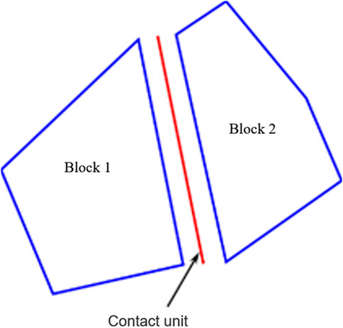
Figure 8. UDEC voronoi block contact diagram.
Figure 9 reflects the flow chart of hard rock fracture propagation based on UDEC meso-simulation method, which mainly includes the following key steps:
(1) Build a model and input parameters. When build the model, the whole block should be cut by voronoi technology in UDEC as the basic calculation model.
(2) Initial equilibrium. Usually refers to the initial equilibrium state under persistent working conditions. The fracture and propagation of hard rock is a relatively long process, which mainly occurs in the persistent condition, so the initial equilibrium state of the persistent condition is taken as the starting point for studying the fracture and propagation of hard rock.
(3) The sub-cycle traverses the contact update parameters. Traverse the contact and check whether the stress of the contact meets the crack initiation condition. If the criterion is met, the contact strength parameters are updated; If the criterion is not met, the next contact object in the contact list is accessed.
(4) Based on the updated contact parameters, the calculated values of the model are balanced. At this time, the stress conditions of contact in the model will generally change.
(5) Increase the time by Δt, carry out cycle calculation, execute the sub-cycle program again, traverse the contact and update the contact parameters.
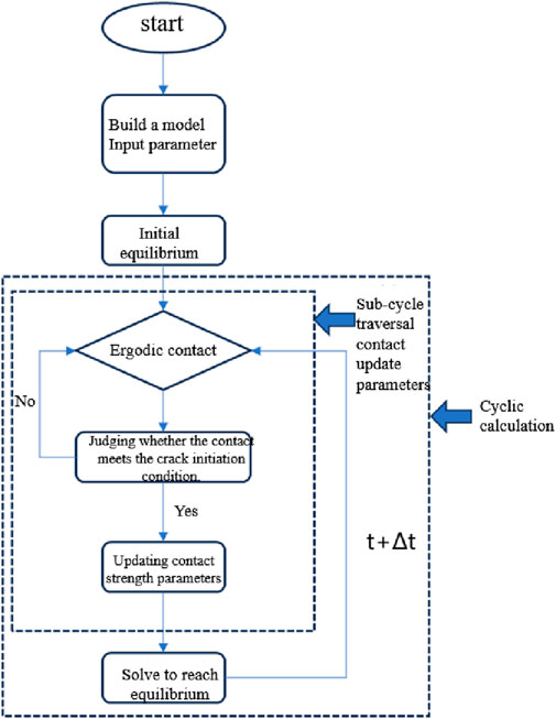
Figure 9. Flow chart of simulating fracture propagation of hard rock based on UDEC.
3.4 UDEC-voronoi calculation and analysis
The steeply inclined joints sporadically distributed outside the steep slopes on the right bank of the M section of the Lancang River extend tens to hundreds of meters, with dip angles slightly greater than the slope angle but less than those of the dominant joint sets. Most of these joints are hidden within the slope surface, with a few exposed at the surface and terminating within the slope (see Figure 10). Based on the numerical simulation results in Figure 6, under the geological structural background of the M section of the Lancang River, significant dislocation deformation occurs along these long joints during the slope formation process, forming a pushing load at the termination ends of the rock masses. When steeply inclined joints, especially those dipping against the slope, are relatively developed at the termination ends, they not only facilitate block rotation but may also cause rock mass rupture, leading to the continuous development of block rotation and the formation of locally distributed push-induced tipping deformation at the termination ends. Although the pushing load at the termination ends of the rock masses favors block rotation deformation, the final manifestation depends on the rock mass structure and confining pressure conditions: if the termination end rock mass is intact or the block shapes formed by joint cutting do not exhibit a rotational tendency, the pushing load may not induce block rotation; if the termination end is located deeper within the slope, higher confining pressure levels also inhibit block rotation deformation. However, regardless of the situation, rock mass rupture may still occur under the pushing load, resulting in diverse forms of rupture phenomena.
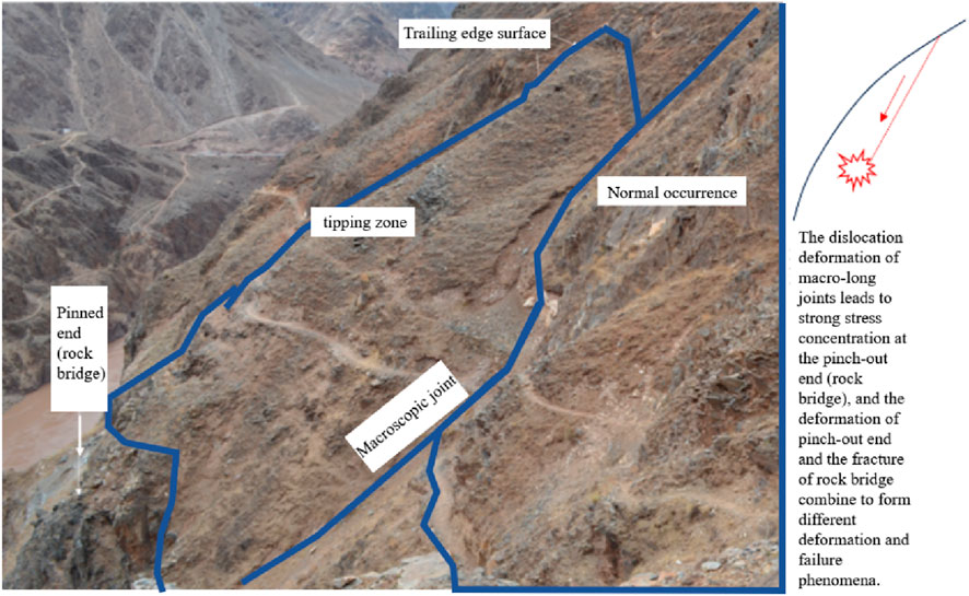
Figure 10. Macro joints and pinching phenomenon on M bank slope.
The photo shown in Figure 11 was taken near PD6 (at an elevation of 2,678 m, see Figure 6) on the steep lower slope section. The steeply dipping downslope joints in this area are relatively small in scale. According to Figure 6, joints with this orientation and distribution location have relatively minor dislocation deformation during the evolution of the river valley slope, and the stress increase at the termination ends is relatively weak. Despite this, in the specific geological structural background of the M section of the Lancang River, arcuate shear fractures still appear at the termination ends. By examining the spatial relationship between joint surfaces, it is obvious that arcuate shear fractures may be formed after the joints along the slope. The two are connected in space, and the slope joint is larger in size, the joint surface is rougher and the arcuate shear fractures is smaller. Compared with weathered and filled slope joints, the relative freshness of arc fracture further proves this point. The relatively young arcuate shear fractures indicate that they are the result of the extension of downslope steeply dipping joints terminal during the slope evolution.
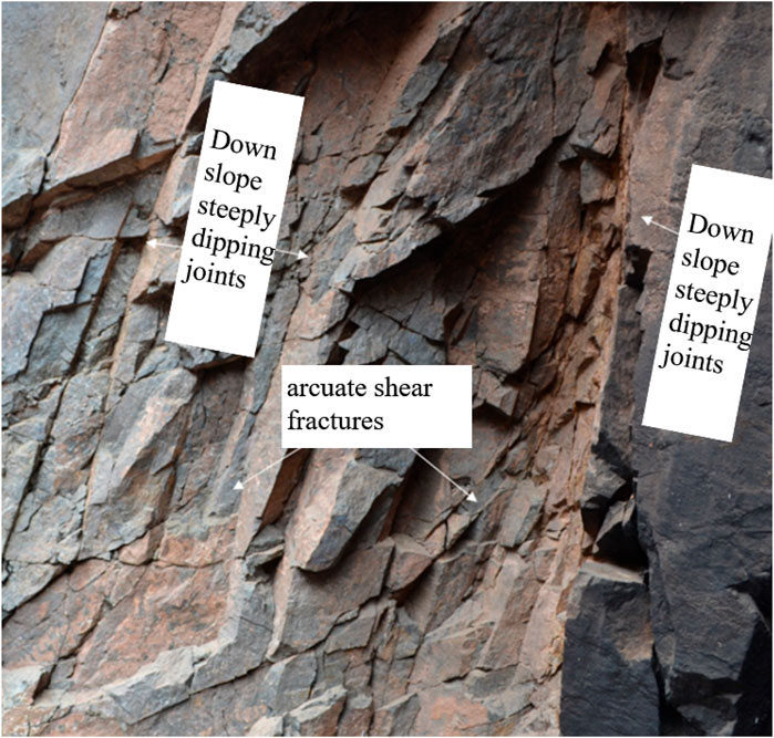
Figure 11. Rock mass fracture phenomenon at the tip out end of macroscopic joints on M bank slope.
It is notable that the downslope steeply dipping joints exhibit significant filling and weathering, whereas the arcuate fractures are relatively fresh, indicating that the latter likely formed much later. This suggests that the arcuate fractures are likely a result of the extension of the termination ends of the downslope joints during the slope evolution process.
The fracture phenomenon shown in Figure 12 occurred on the upper right bank of the M section, as revealed by the adit at an elevation of 3,084 m, corresponding to a horizontal distance of 385 m. The shear fracture zone lacks characteristics of tectonic origin. Referring to the numerical calculation results shown in Figure 6a, this phenomenon aligns with the mechanical mechanism of slope formation, indicating that it is a fracture phenomenon derived from the deformation of the dominant steeply dipping joints on the outer slope during the valley slope formation process. Small joints within the back-slope shear fracture rock mass have developed, but under the influence of the pushing load, they did not result in tipping deformation but rather shear failure. This should be related to the confining pressure at this location during the pushing load, where higher confining pressure levels limited the block rotation.
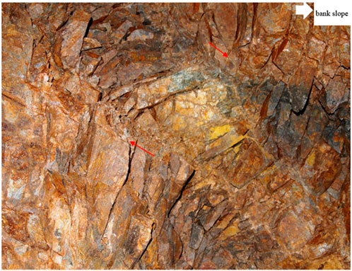
Figure 12. Damage phenomenon at an elevation of 3,084 m and a depth of 385 m.
Rock fracturing is an accompanying phenomenon of hard rock block rotation and an essential condition for the continuous rotation and evolution into tipping. The severe fracturing shown in Figure 13 occurs at the corners of large blocks within the tipping deformation body. This photo was taken at a depth of 185 m in the PD08 adit (see Figure 6), within the tipping deformation body. The fracture range terminates at the large steeply dipping joint on the outer slope. The fracture occurs on the hanging wall of this joint, while the footwall rock mass remains well intact, consistent with the rotational deformation characteristics of the hanging wall rock mass.
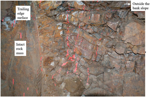
Figure 13. Fracture phenomenon at a depth of 185 m in PD08 adit.
Figure 14 is a UDEC-Voronoi simulation result based on the background of Figure 13, where the Voronoi diagram is only applied to the corresponding location of the fracture shown in Figure 13 (bottom left of Figure 14). In the slope dominated by steeply inclined back joints, a tipping deformation trend appeared during the formation of the river valley slope. The Voronoi model reveals the deformation and fracturing characteristics inside the rotating block at this time. Figure 14 shows the deformation distribution within the rotating block, tending to form transverse fractures within the block. The upper right of Figure 14 is a local magnification result, showing the fracturing phenomenon at this location. This exemplary calculation result shows that when using numerical methods to analyze hard rock tipping problems, it is necessary not only to allow the block boundary to undergo discontinuous deformation such as dislocation and opening but also to simulate the continuous-discontinuous development process of block fracturing.
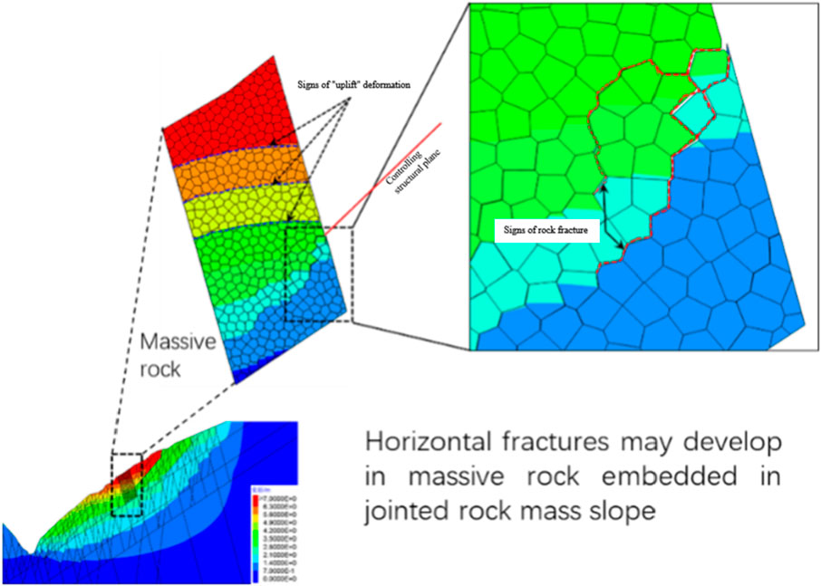
Figure 14. UDEC Voronoi simulation reveals rock mass fracture.
4 Pushing dumping characteristics
4.1 Conditions of occurrence and surface deformation
Figure 15 illustrates the observed translational tipping deformation discovered on the right bank of the M, clearly revealing the conditions under which such tipping deformation occurs and the surface manifestation of the tipping deformation. The translational load is primarily generated by the dislocation deformation of the moderately steeply inclined joints depicted in Figure 15a. Field observations indicate that the dislocation deformation in the central part of this joint reaches nearly 30 cm, while in the lower part of the rock mass where moderately inclined joints are developed, translational deformation occurs under the translational load, as shown in Figure 15b.
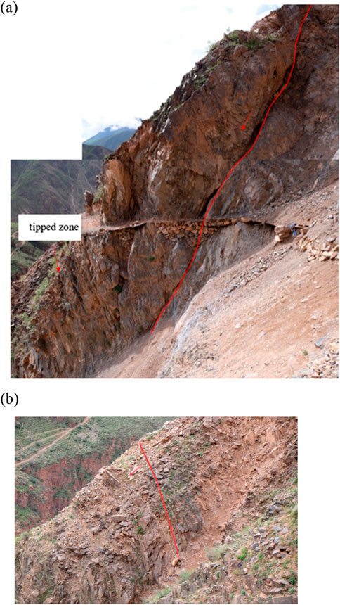
Figure 15. Deformation phenomenon of M right bank push type tipping: (a) External joints and slip deformation of medium steep slopes; (b) The tipping phenomenon at the apex.
The tipping deformation depicted in Figure 15 is limited to the vicinity of the apex and the lower part of the inclined joints where the translational action initiates. Therefore, the maximum deformation does not occur at the crest, unlike the continuous distribution of tipping deformation with maximum deformation at the crest, as previously understood. Figure 15b illustrates the bending deformation of layer-like blocks sliced by the apex joints, with varying degrees of curvature between blocks, differing from previously reported characteristics of tipping deformation.
4.2 Internal deformation and fracture phenomenon
The geological structural planes are characterized by length grading, where larger-scale blocks are cut by longer structural planes, while smaller-scale blocks are formed by secondary joints within the larger blocks. Movement along these larger structural planes drives the rotation of large blocks, affecting the deformation and fracturing of smaller blocks within them. Figure 16 illustrates this scenario on the right bank of the M, where upper blocks undergo movement along longer structural planes, inducing rotational deformation in the lower large blocks. Simultaneously, deformation and even fracturing may occur within the lower blocks. Figure 16 (top left) outlines the conditions under which translational loads occur, and photos A, B, and C, taken successively inside the flat-pit cave, at the shallow part of the flat-pit, and near the cave entrance, respectively, reveal the internal deformation and fracturing of blocks caused by the movement of secondary joints and their segmentation of block rotation, sequentially moving away from the translation zone.
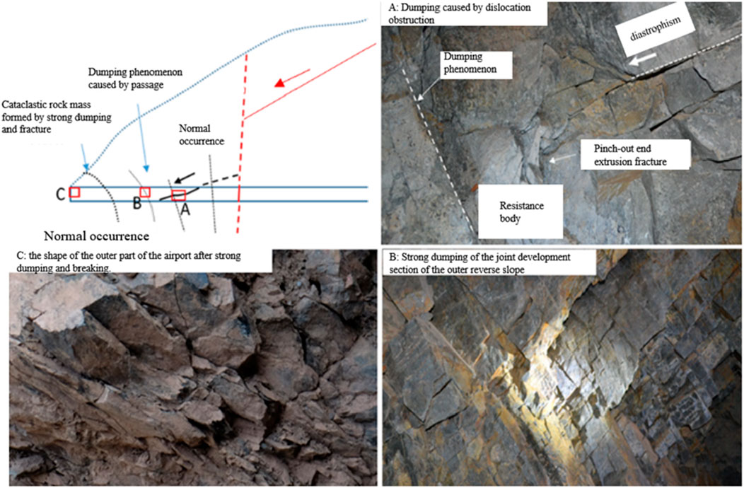
Figure 16. Translational tipping deformation and fracturing. (A) Dumping caused by dislocation obstruction. (B) The shape of the outer part of the airport after strong dumping and breaking. (C) Strong dumping of the joint development section of the outer reverse slope.
Photo A in Figure 16, taken inside the platform, reveals the movement of secondary gentle-dip slope external joints and the resulting fractures at their ends. These fractures mainly include two scenarios: the divergent small cracks extending from the ends of the gentle-dip joints, and the compression fractures occurring at the “sticking” points during the rotation of the shifting blocks. In comparison, the locations shown in Photos B and C are relatively far from the areas affected by the shifting load, characterized primarily by the continuously changing angles of secondary reverse-slope joints, which are typical features for identifying collapse deformation within the platform.
The photo shown in Figure 17, also taken inside the platform on the right bank of the Lancang River, reveals the phenomenon of rock block fractures within the block-like structural collapse body. The rotation of the block causes blockage at the corners, where the formation of micro-cracks relieves the constraint on the rotation of the block, allowing the rotation to continue and causing macroscopic collapse deformation. In other words, rock block fractures are an important component of hard rock collapse and a crucial condition for the collapse deformation of hard rock slopes.
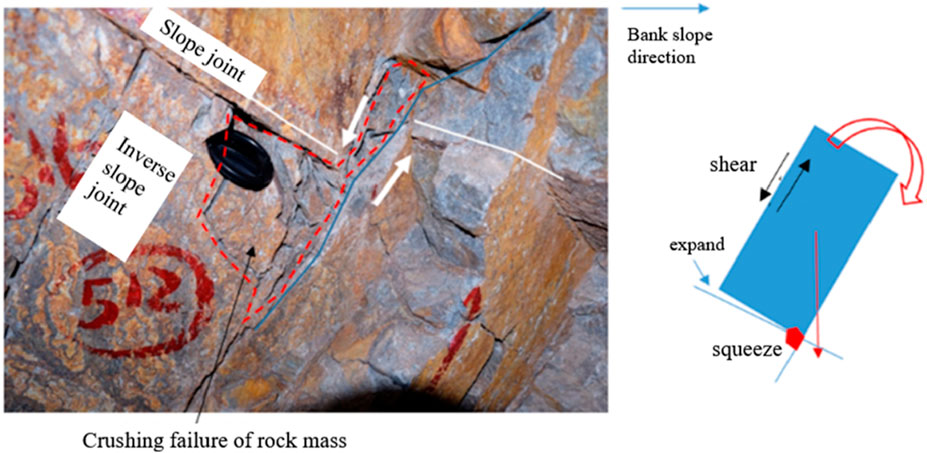
Figure 17. Compression and fracturing of rock blocks within translational tipping bodies.
4.3 Summary of characteristics of promoting dumping
Currently, the G-B model (Goodman and Bray, 1977) serves as an important criterion for the tipping deformation of rock slopes. Building upon the G-B model, Alejano et al. (2018) and others further considered the realistic scenario of rock blocks transforming from sharp edges to rounded edges due to weathering, establishing a theoretical model for the tipping deformation of rounded-edge rock blocks and indicating that such blocks are relatively more prone to tipping deformation. However, whether it is the G-B model or the model established by Alejano et al. (2018), both treat the rock blocks as rigid bodies, ignoring the phenomenon of deformation and destruction of the rock blocks themselves, while only considering the effect of gravity. Therefore, the aforementioned criteria for tipping are mainly applicable to the shallow parts of inclined layered slopes.
For the phenomenon of translational tipping deformation of M hard rock slopes studied in this paper, the applicability of the above criteria is obviously insufficient. The main reason is that there is a significant discrepancy between the assumed conditions of the above criteria and the actual conditions of M slopes, which is manifested specifically in the following two aspects:
1. The differences in stress conditions of rock blocks. Under shallow burial conditions, the rock mass of the slope is in a relaxed unloading zone, mainly subjected to gravitational forces, and the contradiction between the stress on the rock mass and its own strength is not prominent. In this case, considering the rock block as a rigid body and only considering gravitational effects will not cause significant problems. However, for the translational tipping deformation problem of M hard rock studied in this paper, the tipping rock mass is not only subjected to gravitational forces but also to the lateral displacement and compression from the upper rock mass, the latter’s influence can far exceed the former. In addition, translational tipping deformation of M slopes occurs not only in shallow layers but also in deep rock masses. For deep rock masses, the horizontal stress is relatively high, resulting in more complex stress conditions for the rock mass.
2. The differences in deformation and failure characteristics of rock masses. Under shallow burial conditions, the deformation and failure characteristics of the rock mass under its own weight can be basically ignored. However, under the upper lateral displacement and compression load, there is a significant stress concentration phenomenon in local positions of the rock mass (such as the toe of rock blocks and the apex of large-scale slope structures), which have the mechanical conditions to cause rock fractures and extensions. In the research conducted by Alejano et al. (2018), the sharp corners of rock blocks are transformed into rounded corners under the influence of weathering, making them more prone to tipping deformation. For the translational tipping deformation body of M slopes, the sharp corner fractures of rock blocks occur at the toe under stress concentration, which is similar to the weathering of sharp corners of rock blocks studied by Alejano. Therefore, it can be inferred from Alejano’s research conclusion that the fracture of rock block toes in M slope tipping bodies is conducive to the formation and development of tipping deformation.
In summary, considering the high complexity of translational tipping deformation of M slope hard rocks, both the traditional G-B model and the theoretical model established by Alejano are not applicable for distinguishing the translational tipping of M slope hard rocks. Therefore, further in-depth exploration is still needed for the mechanical criteria of M slope hard rock translational tipping, which will be one of the important research contents in the next stage of this paper.
5 Conclusion
Continuous rotation of hard rock blocks requires overcoming the constraint of their own strength, resulting in rock block fracture phenomena. The self-weight of rock blocks is often insufficient to cause rock block fractures, so the tipping of hard rock slopes often relies on external loads. The tipping of M hard rock is the result of the action of translational loads and requires meeting conditions in two aspects:
1. Regional structural conditions: The slope is located in an area with active tectonic movements, and during the formation process of the slope, there is a significant change in rock mass stress, changing the stress conditions of rock blocks through traction or translational means, forming external loads sufficient to cause continuous rotation of rock blocks beyond their own weight.
2. Rock mass structural conditions: The slope develops large structural surfaces outside steep slopes, and the apex of these surfaces has steeply inclined joints. Significant sliding deformations occur during the evolution of the slope, resulting in strong translational effects on the lower apexes of the jointed rock mass.
The hard rock tipping observed on the right bank slope of the Lancang River in the M section meets the above conditions and is the result of translational load action, belonging to hard rock translational tipping. Compared with the characteristics of layered and blocky tipping deformations, where the maximum deformation occurs at the slope top or front edge, M hard rock translational tipping is limited to the apexes of large structural surfaces outside steep slopes, showing clear differences between them.
Another typical feature of M hard rock translational tipping is the widespread occurrence of rock block fractures within the tipping body. This makes hard rock translational tipping subject to the control of both high stress and structural surfaces, belonging to a complex macro-micro discontinuous mechanical coupling problem.
UDC-Voronoi method divides the slope into irregular cells, which makes the simulation more in line with the actual geological conditions. In addition, Voronoi grid can effectively adjust the cell shape when the boundary changes, thus improving the simulation accuracy and calculation efficiency. In contrast, other traditional numerical methods often need a lot of grid division, which is difficult to deal with large-scale deformation.
Data availability statement
The original contributions presented in the study are included in the article/Supplementary Material, further inquiries can be directed to the corresponding author.
Author contributions
WS: Methodology, Software, Writing–original draft, Writing–review and editing. XR: Funding acquisition, Supervision, Writing–original draft, Writing–review and editing. CL: Investigation, Writing–review and editing. YG: Methodology, Supervision, Writing–original draft, Writing–review and editing.
Funding
The author(s) declare that no financial support was received for the research and/or publication of this article.
Conflict of interest
Author WS was employed by Guiyang Engineering Corporation Limited.
The remaining authors declare that the research was conducted in the absence of any commercial or financial relationships that could be construed as a potential conflict of interest.
Generative AI statement
The author(s) declare that no Generative AI was used in the creation of this manuscript.
Publisher’s note
All claims expressed in this article are solely those of the authors and do not necessarily represent those of their affiliated organizations, or those of the publisher, the editors and the reviewers. Any product that may be evaluated in this article, or claim that may be made by its manufacturer, is not guaranteed or endorsed by the publisher.
Supplementary material
The Supplementary Material for this article can be found online at: https://www.frontiersin.org/articles/10.3389/feart.2025.1558435/full#supplementary-material
References
Alejano, L. R., Sánchez-Alonso, C., Pérez-Rey, I., Arzúa, J., Alonso, E., González, J., et al. (2018). Block toppling stability in the case of rock blocks with rounded edges. Eng. Geol. 234, 192–203. doi:10.1016/j.enggeo.2018.01.010
Board, M., Chacon, E., Varona, P., and Lorig, L. (1996). Comparative analysis of toppling behaviour at Chuquicamata open-pit mine, Chile. Trans. Institutions Min. Metallurgy Sect. a-Mining Technol. 105, A11–A21.
Cai, J. C., Ju, N. P., Huang, R. Q., Zheng, D., Zhao, W. H., Li, L. Q., et al. (2019). Mechanism of toppling and deformation in hard rock slope: a case of bank slope of Hydropower Station, Qinghai Province, China. J. Mt. Sci. 16, 924–934. doi:10.1007/s11629-018-5096-x
Cai, J. C., Liu, J. T., Zhang, J., Wang, J. P., Zhang, S., and Qi, G. Q. (2024). Quantitative study on toppling deformation zoning of antidip rock slope under different soft and hard rock conditions. Front. Earth Sci. 12. doi:10.3389/feart.2024.1447578
Fang, R. K., Deng, L. S., Fan, W., Yang, G., Tang, D., and Mohammad, A. (2024). Research on response characteristics of loess slope and disaster mechanism caused by structural plane extension under excavation. Sci. Rep. 14, 28700. doi:10.1038/s41598-024-80016-x
Feng, W. K., Huang, R. Q., and Xu, Q. (2011). Seismic response analysis of horizontal layer slope with soft and hard rock combination. App. Mech. Mat. 90-93, 1326–1333. doi:10.4028/www.scientific.net/amm.90-93.1326
Gao, B. L., Li, L., Chen, L. C., and Yang, Z. F. (2021). Visual research and determination of structural plane and free face of rock slopes. Environ. Earth Sci. 80, 48. doi:10.1007/s12665-020-09340-5
Goodman, R. E., and Bray, J. W. (1977). “Toppling of rock slopes. Rock engineering: American society of civil engineers,” in Geotechnical Engineering Division Conference, Boulder, Colorado.
Guo, H., Yan, C. Z., Zhang, G. H., Xu, R., Wang, T., and Jiao, Y. Y. (2024). Mechanical analysis of toppling failure using FDEM: a case study for soft-hard interbedded anti-dip rock slope. Comput. Geotechnics 165, 105883. doi:10.1016/j.compgeo.2023.105883
Haghgouei, H., Kargar, A. R., Amini, M., and Esmaeili, K. (2020). An analytical solution for analysis of toppling-slumping failure in rock slopes. Eng. Geol. 265, 105396. doi:10.1016/j.enggeo.2019.105396
Huang, D., Ma, H., and Huang, R. Q. (2022). Deep-seated toppling deformations of rock slopes in western China. Landslides 19, 809–827. doi:10.1007/s10346-021-01829-9
Huang, R. Q. (2007). Large-scale landslides and their sliding mechanisms in China since the 20th century Chinese. J. Rock Mech. Eng., 433–454. doi:10.3321/j.issn:1000-6915.2007.03.001
Huang, R. Q., Wang, Y. S., Wang, S. T., and Li, Y. S. (2011). High geo-stress distribution and high geo-stress concentration area models for eastern margin of Qinghai-Tibet plateau. Sci. China-Technological Sci. 54, 154–166. doi:10.1007/s11431-011-4652-1
Jiang, W., Fu, Z. Y., Wang, J. X., and Zhang, H. R. (2023). Effect of initial geo-stress on deformation of anti-dip layered rock slopes. South China Geol. 39, 108–115. doi:10.3969/j.issn2097-0013.2023.01.009
Kaiser, P. K., and Kim, B. H. (2008). “Rock mechanics challenges in underground construction and mining,” in Proceedings of the First Southern Hemisphere International Rock Mechanics Symposium, 23–38. doi:10.36487/acg_repo/808_83
Lu, W. B., Yan, E. C., Zou, H., and Zhang, S. S. (2017). Development rules of toppling deformation slopes in China. J. Changjiang River Sci. Res. Inst. 34, 111–119. doi:10.11988/ckyyb.20160484
Ma, W. L., Li, J. F., Wang, H. R., and Meng, X. Z. (2024). Investigating the evolution chain of deformation and destabilisation of anti-dip rock slopes. Nat. Hazards. doi:10.1007/s11069-024-07067-1
Melnikov, N. N., Kozyrev, A. A., Reshetnyak, S. P., Kasparian, E. V., and Rybin, V. V. (2004). Methodical approach to value of an optimal open pit slope angle in hard rocks. Rotterdam: Millpress Science Publishers. doi:10.13140/2.1.2438.1441
Miao, C. X., Liu, J. W., Gao, M. L., Li, J., Pang, D. D., and Yuan, K. F. (2024). Insight into the overload failure mechanism of anchored slope with weak structural planes. Bull. Eng. Geol. Environ. 83, 390. doi:10.1007/s10064-024-03895-4
Ning, Y. B., Tang, H. M., Zhang, B. C., Ding, B. D., Shen, P. W., Xia, D., et al. (2021). Evolution process and failure mechanism of a deep-seated toppling slope in the Lancang River Basin Chinese. J. Rock Mech. Eng. 40, 2199–2213. doi:10.13722/j.cnki.jrme.2020.1071
Ren, G. M., Xia, M., Li, G., Liu, C., and Zhang, F. R. (2009). Study on toppling deformation and failure characteristics of steep bedding rock slope. Chin. J. Rock Mech. Eng. 28, 3193–3200. doi:10.3321/j.issn:1000-6915.2009.z1.090
Song, D. Q., Chen, J. D., and Cai, J. H. (2018). Deformation monitoring of rock slope with weak bedding structural plane subject to tunnel excavation. Arabian J. Geosciences 11, 251. doi:10.1007/s12517-018-3602-7
Sun, S. R., Sun, H. Y., Wang, Y. J., Wei, J. H., Liu, J., and Kanungo, D. P. (2014). Effect of the combination characteristics of rock structural plane on the stability of a rock-mass slope. Bull. Eng. Geol. Environ. 73, 987–995. doi:10.1007/s10064-014-0593-9
Wang, R. Q., Zheng, Y., Chen, C. X., and Zhang, W. (2023). Theoretical and numerical analysis of flexural toppling failure in soft-hard interbedded anti-dip rock slopes. Eng. Geol. 312, 106923. doi:10.1016/j.enggeo.2022.106923
Wang, S. Y., Yu, S. Y., Hu, X. Y., and Yang, B. K. (2024a). Effects of folded fissure properties on tunnel model failure: experiments and numerical simulations. Eng. Fract. Mech. 310, 110487. doi:10.1016/j.engfracmech.2024.110487
Wang, S. Y., Yu, S. Y., and Ren, Z. K. (2024b). Modelling the blast cracking processes of rock masses using a total Lagrange meshless method. Case Stud. Constr. Mater. 21, e03673. doi:10.1016/j.cscm.2024.e03673
Wang, W., Wang, D. J., Chen, Z. S., and Qiao, X. J. (2017). Present-day strain rate field of Tibetan plateau analyzed by GPS measurements. J. Geodesy Geodyn. 37, 881–883+897. doi:10.14075/j.jgg.2017.09.001
Wyllie, D., and Mah, C. (2017). Rock slope engineering: civil and mining. 4th edition, 1–432. doi:10.1201/9781315274980
Yu, S. Y., Yang, X. K., Ren, X. H., Zhang, J. X., Gao, Y., and Zhang, T. (2023). Shear damage simulations of rock masses containing fissure-holes using an improved SPH method. Materials 16, 2640. doi:10.3390/ma16072640
Zhang, H. N., Chen, C. X., Zheng, Y., Yu, Q. Q., and Zhang, W. (2020). Centrifuge modeling of layered rock slopes susceptible to block-flexure toppling failure. Bull. Eng. Geol. Environ. 79, 3815–3831. doi:10.1007/s10064-020-01797-9
Zhang, L. T., and Tang, S. B. (2024). Investigating the toppling failure of anti-dip rock slopes containing non-persistent cross-joints via a strength-based fracture method. Eng. Geol. 333, 107491. doi:10.1016/j.enggeo.2024.107491
Keywords: layered tipping, hard rock translation-type tipping, discontinuous deformation, rock block fracture, UDEC-voronoi
Citation: Sun W, Ren X, Lu C and Gao Y (2025) The study of fracture phenomena and translational tipping deformation in M hard rock slopes. Front. Earth Sci. 13:1558435. doi: 10.3389/feart.2025.1558435
Received: 10 January 2025; Accepted: 24 March 2025;
Published: 09 April 2025.
Edited by:
Chong Xu, Ministry of Emergency Management, ChinaReviewed by:
Chuang Wang, North China University of Water Conservancy and Electric Power, ChinaJuan Du, China University of Geosciences Wuhan, China
Fang-Peng Cui, China University of Mining and Technology, Beijing, China
Tiantao Li, Chengdu University of Technology, China
Copyright © 2025 Sun, Ren, Lu and Gao. This is an open-access article distributed under the terms of the Creative Commons Attribution License (CC BY). The use, distribution or reproduction in other forums is permitted, provided the original author(s) and the copyright owner(s) are credited and that the original publication in this journal is cited, in accordance with accepted academic practice. No use, distribution or reproduction is permitted which does not comply with these terms.
*Correspondence: Xuhua Ren, cmVueGhAaGh1LmVkdS5jbg==