 Yunhong Lin
 Guoxu Cao
94% of researchers rate our articles as excellent or good
Learn more about the work of our research integrity team to safeguard the quality of each article we publish.
Find out more
ORIGINAL RESEARCH article
Front. Earth Sci., 14 March 2025
Sec. Geohazards and Georisks
Volume 13 - 2025 | https://doi.org/10.3389/feart.2025.1553754
The shield crossing an anchor cable zone can cause the anchor cable to wrap around the cutter, creating construction problems. To address this issue, we developed an improved cutterhead technology for the shield machine which was successfully used during the Zhengzhou Metro Line four tunnel project that crossed a large anchor cable zone. Our research outlines the technology’s configuration and provides a detailed analysis of the tunneling parameters in the anchor cable section. This innovative technology directly cuts anchor cables during construction and improves both the shield machine and tunneling parameters.
The rapidly developing domestic rail transportation industry has resulted in an increasingly dense network of subway tunnels (Lin et al., 2023). Moreover, the complexity of situations encountered during shield construction in subway intervals has been increasing (Bai et al., 2014). An increasing number of scholars are investigating how shield construction can be performed in complex situations.
Shield tunnels may traverse the sides or depths of large buildings or underground structures that utilize pile-anchor systems, creating an obstacle known as the anchor zone, a complex condition faced in shield tunneling (Zheng et al., 2023; Ding et al., 2023; Fall et al., 2019). Previously, it was thought that while passing through the anchor cable area, the shield tunneling machine’s cutter head could entangle the anchor cable or obstruct its conveyance structure, leading to issues such as damage to the cable steel wire or cutter head, compromising construction progress with high risks and expenses (Han et al., 2022). Scholars and experts have investigated the issue of shield tunnels encountering the anchor zone. Wang et al. (2023) suggested removing obstacle piles in Shenyang subway tunnel construction using either the pile support method or direct piling method. Wang (2020) presented three anchor treatment techniques (open excavation, mixing pile, and rotary drilling) used in constructing the shield interval of Rail Transit Line 5, proven feasible through monitoring. Chao et al. (2022) accelerated the construction process by utilizing rotary drilling cutting and triaxial mixing piles for anchor cable removal in the shield crossing anchor cable area. Ding et al. (2023) accomplished traversing the vast anchor cable zone by employing a combination of rotary pile anchor pulling, high-pressure jet grouting piles, and double pipe processing anchors when crossing the anchor zone with the shield. Han et al. (2023) recommended using a construction scheme involving steel sheet piles and injection grouting piles for constructing top-tube tunnels that cross the anchor zone. Jiayun (2021) provided an example of using steel sleeve and manual anchor cable extraction to handle anchor cables while crossing the anchor zone with the shield, specifically in the Shaoxing Metro Line one interval. Lv (2017) presented the treatment technology of combining deep well digging under pressure with manual excavation and hydraulic jack anchor extraction to remove groups of large anchor cables. Du and Banhu (2017) utilized shaft plus cross passage construction to eliminate anchor cables encountered in shield tunneling, overcoming the impact of deeply buried long-distance anchor cables on the shield tunneling process. Han (2018) scrutinized the method of removing anchor cable obstacles by drilling holes using deformable rigid casing and a ball drill bit to dislodge anchor solids adhering to the strata, citing the Zhengzhou Line 5 shield crossing anchor cable area as an example.
Most previous studies remove anchor cables before shield tunnel construction, a safe and reliable but laborious, time-consuming, and costly process. However, fieldwork has shown that modifications to shield tools can effectively sever pile anchors during shield tunneling (Lei et al., 2013; Li et al., 2021; Li et al., 2021; Wang et al., 2013; Yuan et al., 2016). Thus, this study combines direct cutting of anchor cables with improved shield machine design and strict control of tunneling parameters to cross the anchor zone around the foundation pit in Zhengzhou City Rail Transit Line 4, significantly saving time and cost. The paper is organized as follows: Section 2 presents the improved shield machine cutter design, Section 3 provides engineering background information, Section 4 analyzes tunneling parameters through the anchor cable section in detail, and Section 5 discusses technical points and effects of shield tunneling.
The selection of a shield machine considers factors such as the excavation surface’s soil condition, groundwater level, obstacles, design route, tunnel length, construction period, environmental impact, cost-effectiveness, and past experience. Considering the reasons for the capacity of the slurry shield slag pump, the cutting will damage the slag pump and cannot be used. The cutting anchor cable shield machine of this project adopts the earth pressure balance shield machine by China Railway Engineering Equipment Group Co., Ltd., and the excavation diameter is 6,470 mm. This machine has six electric motor drives that provide a combined power of 660 KW, a rated torque of 5500kNm, and a breakout torque of 6800kNm, capable of meeting the excavation torque requirements of high-torque demand strata like sand layers.
To cross the anchor zone in this section, we choose a composite cutterhead with an excavation diameter of 6470 mm, four foam ports, and 2 bentonite ports for improved spoil excavation. In order to better cut the anchor cable, the cutter head is equipped with 69 high alloy shell-type tearing knives. The height of the knives is arranged in a three-dimensional arrangement. There are four kinds of 220 mm, 175 mm, 165 mm and 140 mm, which are all arranged in the main beam. The height of the knives is 220 mm (2), 140 mm (23), 165 mm (19) and 175 mm (3). The auxiliary beam of the cutterhead is arranged with 22 replaceable tearing knives, with a height of 165 mm (20 knives) and 175 mm (2 knives). The outer circumference of the cutterhead was arranged with 12 groups of diameter-keeping tearing knives, and the knife heights were 140 mm (6 groups), 165 mm (2 groups) and 175 mm (4 groups). Aiming at the problem of cutting anchor cable in this project, the cutter head is specially added with a heightening knife, that is, 5 tearing knives with a height of 175 mm, 6 groups of diameter-preserving knives with a height of 175 mm, with an interval of about 420–450 mm, as shown in Figure 1. The heightening knife is 10 mm higher than the nearby tearing knife, which is used to cut the anchor cable. The anchor cable is cut into a length of about 450 mm, and then the anchor cable is ripped off by other tearing knives. The cutting tools feature center-reinforced dual-connected ripping blades (Figure 1A), front-reinforced replaceable ripping blades (Figure 1B), 12 17-inch edge roller blades on the outer ring of the cutterhead, and 23 front welding ripping blades welded along the panel trajectory (Figure 1C). This blade arrangement enhances cutterhead tool strength, ensures anchor breaking, and places the replaceable ripping blade’s height in the pile zone higher than that of the welded ripping blade to enhance anchor cutting efficiency and reliability. Additionally, 8 side scraper blades extend continuous excavation distance in sand layers and reduce impact dropping, while 36 cutting blades, 8 diameter retaining blades, and 16 cutterhead protection blades improve the cutterhead large ring’s wear resistance and protect the cutterhead body from damage. Cutterhead height difference schematic diagram is shown in Figure 1D, and the overall cutterhead arrangement is illustrated in Figure 2.
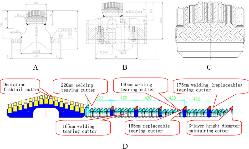
Figure 1. Illustration of the improved layout of the cutterhead (A) Dual-center tearing cutter, (B) Replaceable tearing cutter, (C) Welded tearing cutter, (D) Elevation of the cutterhead.
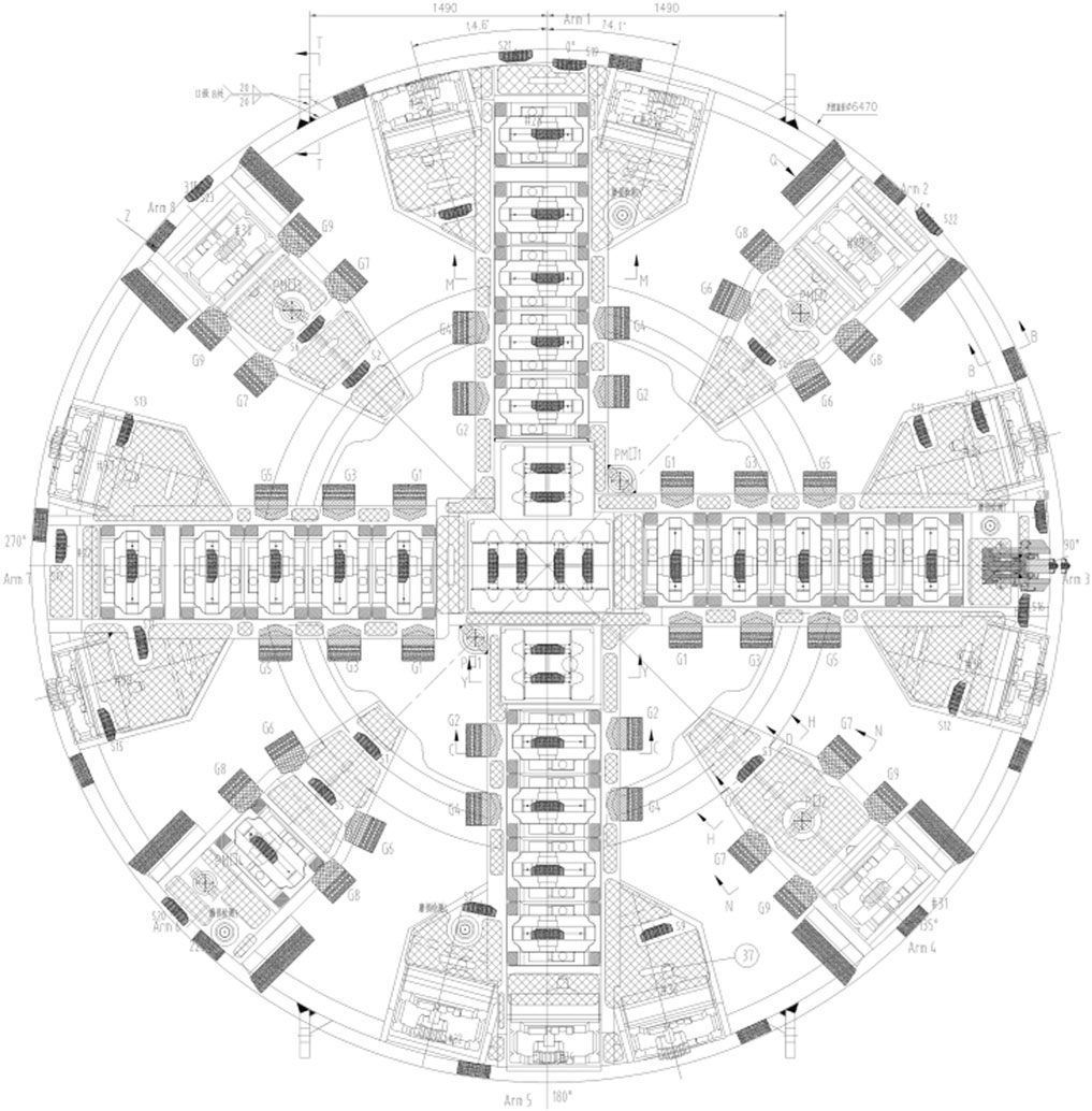
Figure 2. Diagram of shield machine’s cutter plate.
In the cutting process of the anchor cable, if the addition of the soil modifier is not ideal or the rotation speed of the cutter head is not properly controlled, the alloy chipping of the tearing knife may occur. For this reason, the tool selection is considered in a targeted manner, and the cutting edge of the tearing knife and the retaining knife is subjected to an arc transition treatment, as shown in Figure 3.

Figure 3. Cutting edge treatment comparison. (A) Conventional scheme (cutting edge without circular arc transition treatment), (B) This scheme (cutting edge circular arc transition treatment).
To prevent excavation difficulties caused by cutterhead blockages, we place four mixing rods at three different cutterhead radii. As the cutterhead rotates, these rods mix the soil in the soil bin with two passive mixers on the front shield. This process ensures that added materials (mud, water, foam) injected on the excavation surface or in the soil bin mix thoroughly with the excavated soil, enhancing its plasticity and flowability. All cutterhead pipelines are located at the back (with protection) and can be replaced within the tunnel when fully blocked and incapable of cleaning. The nozzle assembly can be entirely extracted from the back of the cutterhead for repair or replacement when wholly damaged or blocked and cannot be dredged. A specific layout is illustrated in Figure 4.
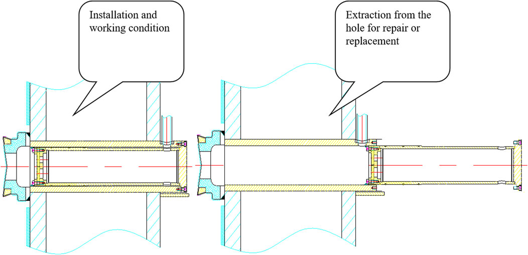
Figure 4. Schematic diagram of nozzle replacement.
To avoid blowouts and nozzle blockages, we equip the shield machine with a slurry treatment system with ample capacity that includes a foam injection system and a bentonite injection system. The rotating joint features separate channels for foam and bentonite, and the cutting head has a slurry treatment agent nozzle with a check valve and a protective device to prevent nozzle blockages. Our specific model comes with a 5-channel single-pipe, single-pump, single-nozzle foam injection system that injects foam into the cutting head’s front five nozzles through a 5-channel rotating joint. Fully mixed in the mixing box, the foam is pumped and foamed for enhanced performance and reduced consumption. Each foam pipeline can still inject the designated amount of foam even when nozzle resistance varies, reducing potential nozzle blockages. The nozzle assembly can be entirely detached from the cutting head’s back for replacement or repair within the tunnel if wholly blocked and cannot be cleared. All cutting head pipelines are located at the back (with protection) and can be replaced within the tunnel when fully blocked and incapable of cleaning. We also install a bentonite injection system using a high-lift extrusion pump (160 m) to ensure adequate injection. Our equipment configuration permits simultaneous foam and bentonite injection in front of the cutting head, and comprehensive slurry treatment effectively prevents blowouts.
The enhanced shield cutterhead system is operational in the Zhengzhou Metro Line 4, spanning 30.126 km from Huiji People’s Hospital to the Economic and Technological Development Zone.
The section between Ruyi Hubei Station and Convention and Exhibition Center Station spans over Zhengdong New Area and Jinshui Districts. It starts at CK18 + 457.863 on the right, ending at CK19 + 472.154 on the right, with a total length of approximately 1,015 m. The left and right lines measure around 13.0–17.0 m in width, while the section bottom plate’s elevation ranges from 66.40 to 79.84 m. The maximum burial depth of the section tunnel reaches roughly 30.0 m. It follows the wetland park in Zhengdong New Area and passes beneath Ruyi Lake to reach Convention and Exhibition Center Station, following a construction line that primarily runs from Ruyi Hubei Station, under CBD Park and Ruyi Lake, before turning into Zhongzhou Avenue. Along its path, it traverses vital transportation channels and urban structures. A commercial hotel is situated on the western side of Ruyi Lake North Station ∼ Convention Center Station. Its podium foundation support structure features a pile anchor system comprising 900 mm diameter bored piles and inter-pile prestressed anchor cables. The system comprises five layers of anchor cables, with 150 mm diameter holes and a 1.5 m horizontal spacing, reinforced with 15.24 mm2, 1860-grade bonded steel hinges. When constructing the section between Ruyi Hubei Station and Exhibition Center Station for Zhengzhou Metro Line 4, this area encountered the foundation pit support structure’s anchor cable zone for the Zhengzhou Exhibition Hotel podium while shield tunneling from Ring 115 to Ring 250. The closest proximity between the section tunnel and the foundation pit support structure is just 9 m; the relative position relationship is illustrated in Figures 5, 6.
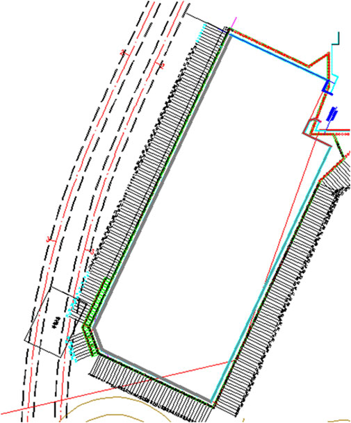
Figure 5. Plan view of subway section and foundation pit anchor cables.
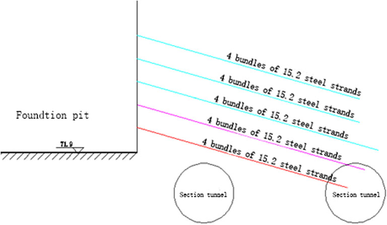
Figure 6. Section diagram of subway section and foundation pit anchor cable.
According to the geological origin, lithology, and engineering characteristics of the rock and soil, the strata between Ruyi Hubei Station and Exhibition Center Station are mainly composed of artificial fill and Quaternary Holocene (Q4) silty clay, silt, and fine sand, Quaternary Upper Pleistocene (Q3) silty clay, silt, and Quaternary Middle Pleistocene (Q2) silty clay, silt, and other soil layers. According to their different origins, their age, and their physical and mechanical properties, the soil layers within the survey depth can be divided into 14 engineering geological unit layers from top to bottom, as shown in Figure 7, which are: ① one miscellaneous fill (Q4 mL), layer thickness 0.6–4.0 m; ② 31 clay silt (Q4aL), layer thickness 0.5–4.0 m; ② 31 B silty clay (Q4aL), layer thickness 0.8–2.5 m; ② 32 clayey silt (Q4aL), layer thickness 1.6–8.8 m; ② 21 Silty clay (Q4aL), layer thickness 0.6–2.5 m; ② 33 clayey silt (Q4aL), layer thickness 1.3–7.3 m; ② 22 silty clay (Q4aL), layer thickness 0.7–7.0 m; ② 34 clayey silt (Q4aL), layer thickness 0.9–4.7 m; ② 41 Silty sand (Q4aL), layer thickness 1.0–4.5 m; ② 51 fine sand (Q4aL), layer thickness 6.5–12.5 m; ③ 24 silty clay (Q3aL), layer thickness 1.0–7.5 m; ③ 25 silty clay (Q3aL), layer thickness 3.3–11.3 m; ③ 25D fine sand (Q3aL), layer thickness 1.0–110 m; ③ 26 silty clay (Q3aL), layer thickness 3.2–9.8 m; ④ 21 Silty clay (Q2aL), layer thickness 2.0–11.5 m; ④ 21D fine sand (Q2aL), layer thickness 2.0–2.2 m.
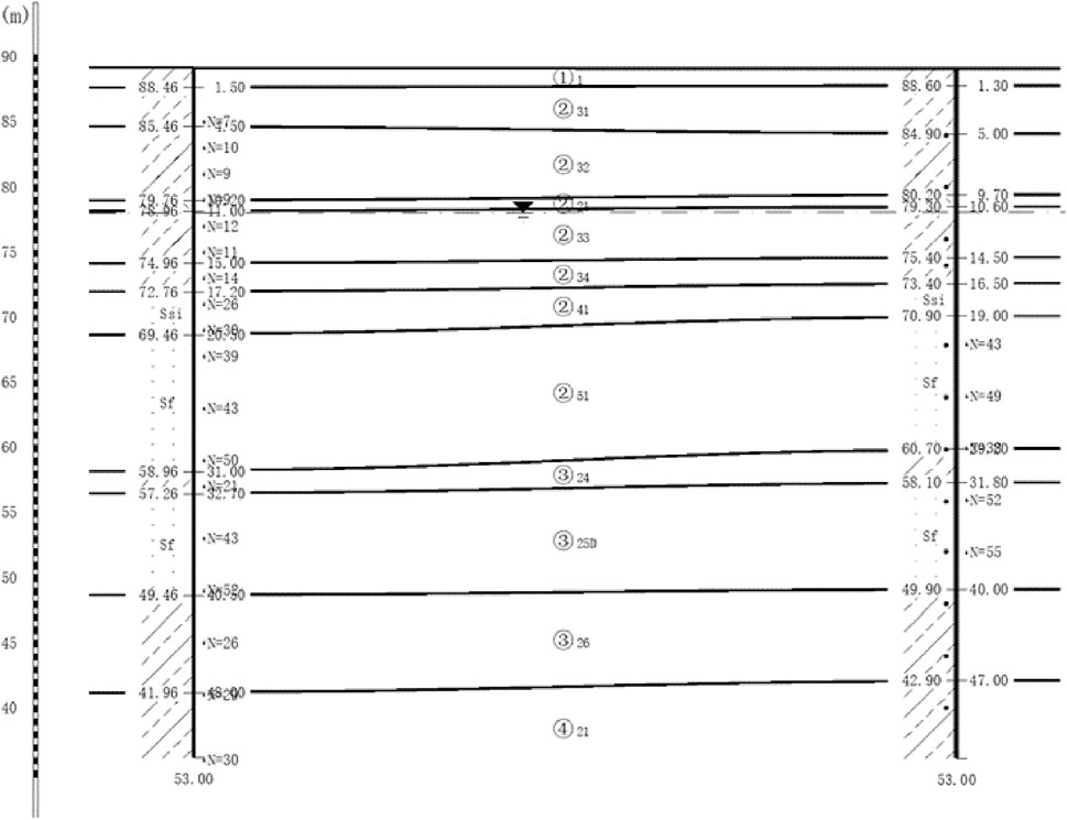
Figure 7. Geological profile map in the Zhengzhou Metro Line 4.
The groundwater levels present between Ruyi Hubei Station and Exhibition Center Station include phreatic water and slightly pressurized water. Diving water generally appears within weakly permeable soil layers like the ② 33 and ② 34 clay silt layers. As per the survey, the stable burial depth of the diving water level varied from 9.2 to 11.1 m (water level elevation 78.7–80.8 m) at the construction site, with an annual fluctuation of roughly 2.0 m. Pressurized water mainly exists in the aquifer layers comprising ② 41 silt and ② 51 fine sand. The top layer of the aquifer sits at a depth of 16.3–21.0 m (elevation 70.4–74.3 m), while the bottom plate is buried between 28.0–34.5 m depths (elevation 56.8–62.5 m), and the pressure head measures approximately 5.0 m.
In order to facilitate the smooth removal of the cutting anchor cable, a screw conveyor with a diameter of A900 mm was selected in the design process of the shield machine. The maximum particle size that can pass is 340 × 560 mm, which meets the discharge of large calcareous nodules, boulders and anchor cable cutting sections that may be encountered in the formation; the gap between the spiral shaft and the cylinder section is optimized, and the gap is only 6 mm, which reduces the probability of the anchor cable cutting section being stuck when cutting through the pile, as detailed in Figure 8 and Table 1 below.
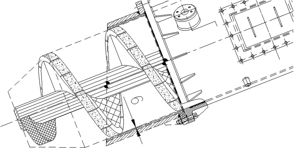
Figure 8. Screw conveyor schematic diagram.

Table 1. Targeted design of screw conveyor.
Figure 9A illustrates the correlation between the shield tunneling machine’s excavation speed and the ring count during subway section construction while crossing the anchor cable area. As observed in the graph, the excavation speed fluctuates significantly between 115 and 151 rings. A declining trend is noticeable in the average excavation speed between rings 152 and 180. However, the excavation speed increases once again after 180 cycles. According to the tunneling speed of shield machine and the construction scheme of crossing the anchor cable area specified before construction, in order to ensure the smooth and continuous passage of the cutting anchor cable area of shield machine, the technical scheme of high torque and low rate is adopted in the construction scheme and concrete implementation process, 6–8 cm/rotation. In this case, it can be ensured that the anchor cable is more cut off by the cutter head, so as to prevent the occurrence of winding on the cutter head due to the too fast excavation and the failure of some anchor cables to cut off in time. According to the cutterhead situation after the completion of the construction, the technical scheme has achieved the planned effect. Considered from the standpoint of shield tunneling velocity, the upgraded shield tunneling machine propels consistently throughout the entire progress of shield tunneling through the anchor cable area. No obstacles have been encountered due to anchor cables entangling the cutter head, which might hinder the construction work’s advancement.
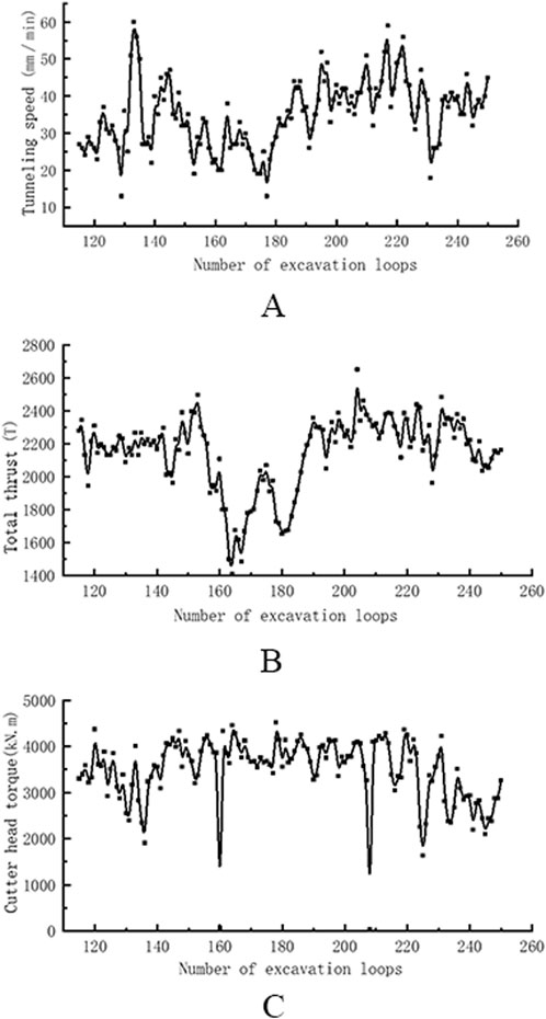
Figure 9. Parameter graphs of the shield cutting in the anchor zone (A) Tunneling speed, (B) Gross thrust, (C) Torque of cutter head.
The relationship between total thrust and the number of rings during shield tunneling through the anchor cable area is presented in Figure 9B. The figure highlights that from ring 115 to 158, the total thrust is relatively stable with minimal fluctuations. Between rings 158 and 188, significant fluctuations in data and a substantial decrease in the total thrust of the shield tunneling machine are observed. The minimum total thrust declined to 1400 T. However, from ring 188 to 250, the total thrust stabilizes with relatively small data fluctuations. Additionally, the total thrust of the shield tunneling machine indicates the two lowest points around rings 165 and 180, which are in line with a decrease in the shield tunneling speed shown in Figure 9A. The excavation process revealed a total of 30 rings with significant fluctuations in total thrust, accounting for approximately 22% of the rings in the anchor cable area of shield tunneling. Notably, the fluctuation range of the total thrust remained within the specified limit throughout the entire crossing process, indicating smooth crossing through the anchor cable area made possible by the improved cutterhead.
Figure 9C illustrates the relationship between the total thrust of the shield tunneling machine and the number of rings in the anchor cable area. The torque of the shield machine cutterhead is observed to decrease to 0 at rings 160 and 208. Significantly, at the 136 and 225 ring shield tunneling machines, there is a substantial decrease in the cutter head torque, followed by an increase. Between rings 137 and 224, the torque of the cutterhead remains relatively stable. With the exception of the two aforementioned rings, the cutter head torque varied within the range of 1,635–4521 kN/m during the excavation process of crossing the anchor cable area, with controllable variation amplitudes.
Figure 10 illustrates the relationship between the quantity of slag produced by the shield tunneling machine and the number of rings during the excavation process through the anchor cable area. With the exception of ring 211, where the slag output suddenly decreased to 5 m3, the slag output from other rings remained relatively stable at 54–55 m3. Notably, there were no significant variations in the slag output during the entire excavation process.
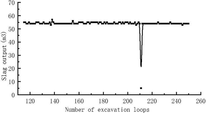
Figure 10. Graph of the slag output from the shield through the anchor cable zone.
The simulation analysis indicates that, with few exceptions, the excavation speed, total thrust, cutterhead torque, and slag output of the shield tunneling machine are subject to normal fluctuations during the excavation of the anchor cable area. Although it is relatively challenging compared to other areas, it can be overcome through improvements to the shield machine and strict control of construction parameters. These findings suggest that improvements to the shield machine and control of construction parameters can effectively facilitate the excavation process despite the presence of anchor cables.
In addition to improving the shield machine, emphasis should also be placed on managing tunneling technology during the process of shield tunneling, including the attitude control of the shield machine and synchronous grouting. During the construction of the Ruyi Hubei Station Convention and Exhibition Center Station, several main tunneling technologies were employed. Firstly, the posture of the shield tunneling must be controlled to prevent significant deviation correction, upward floating, kowtowing, or retreat of the shield tunneling. Furthermore, when constructing curved sections, overbreak should be minimized. Secondly, the main excavation parameters should be strictly controlled, including the cutterhead and soil chamber pressure, soil discharge amount, propulsion speed, total jack thrust, grouting pressure and time, grouting amount, slurry performance, and shield posture. Pushing speed can be adjusted by setting the pushing speed, adjusting the amount of soil discharged, or setting the amount of soil to be discharged. A low-speed, uniform excavation method can be adopted to ensure a balance between soil tank pressure and formation pressure. Measures such as adjusting the composition and dosage of additives at any time can be taken to improve soil quality as changes occur in the composition of geological particles. Thirdly, 15 cycles in advance, shield tunneling parameters should be adjusted, and control measures for the shield tunneling machine’s propulsion should be taken, such as appropriately reducing the pressure of the shield tunneling soil chamber and thrust, and strictly controlling the soil output and propulsion speed to reduce soil displacement caused by formation loss. Fourthly, synchronous grouting should be carried out for the annular gap before advancing, and grouting detection technology can be used to ensure full and sufficient grouting to achieve timely filling of the annular gap and reduce strata displacement caused by insufficient grouting. Fifthly, monitoring points should be arranged on corresponding pile foundations, and the pile foundation should be closely monitored in advance to provide timely feedback on monitoring information and adjust the excavation parameters of the shield machine, ensuring the safe and smooth passage of the shield machine. Lastly, after the shield tunneling passes, a comprehensive evaluation should be conducted on the impact of structures such as pile foundations, rivers, and Ruyi Lake based on monitoring results. Based on the evaluation results, secondary reinforcement grouting should be carried out on the back of the pipe segment and around the pile foundation and other structures through reserved grouting holes. Ground grouting can also be used to improve the friction between the pile foundation and the formation if necessary.
Figure 11 depicts the on-site tunneling situation depicting the shield machine passing through the anchor cable area. Figure 11A showcases the winding of the anchor cable on the cutterhead after passing through the anchor cable area. The absence of large-scale winding on the cutterhead indicates that the cutting effect was excellent throughout the entire process of crossing the anchor cable area, which is supported by the changes in parameters such as thrust and torque during shield tunneling. Furthermore, it can be inferred that there was no jamming of the cutterhead. Figures 11B, C present the stirring effect of the anchor cable after being cut by the shield machine. From the stirring effect, it is evident that most cut anchor cables are scattered over a length of 50–120 cm and output from the screw conveyor. Overall, the effect of the shield machine crossing the anchor cable area was satisfactory.
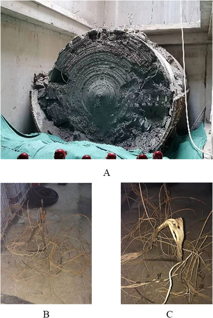
Figure 11. Site view of the shield crossing the anchor cable zone (A) Cutter diagram, (B) Anchor cable diagram, (C) Anchor cable diagram.
Figure 12 illustrates the condition of the cutterhead after the shield machine passes through the anchor cable area. Due to the improved shield tunneling machine and strict control of excavation parameters, the overall effect of the machine passing through the anchor cable area was satisfactory. There was no damage or entanglement of the cutterhead or its bearings from the anchor cable, no obstruction of the screw conveyor, and no excavation difficulties. Notably, the wear of the improved cutterhead tearing knife was approximately 60%. Although the anchor cable damaged the cutterhead considerably, tearing it in the process of shield tunneling through the anchor cable area, the wear level of other tools remained within the normal range, and there was no deformation of the cutterhead. Therefore, the improved cutter head could efficiently and cost-effectively cut the anchor cable directly during shield tunneling if construction parameters were strictly controlled.
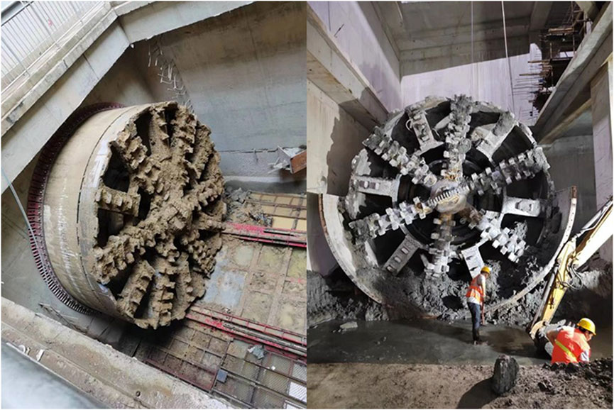
Figure 12. Abrasion diagram of the cutter after the shield crosses the anchor cable zone.
Using the section from Ruyi Hubei Station to Convention and Exhibition Center Station of Zhengzhou Metro Line 4 as a case study, this paper investigates the shield tunneling construction process. Based on our findings, we propose targeted measures for enhancing the shield tunneling machine and controlling construction parameters during the tunneling process.
In order to ensure that the shield machine cuts through the anchor cable at one time and ensures the smooth removal of the anchor cable cut by the anchor cable, the shield machine adds a heavy tearing knife in the cutter configuration, and uses a large diameter (diameter of A900 mm) screw conveyor. The special design of mixing rod, cutter head foam, bentonite nozzle and miscellaneous soil improvement is more convenient for the smooth removal of cutting muck. In the control of the shield machine, the control concept of low speed and high torque is used to keep the shield machine continuously tunneling through the anchor cable area at one time.
At present, the scheme of clearing obstacles in advance is commonly used to deal with the anchor cables on the tunnel path, but this method has long construction time and high construction cost. Through the improvement scheme of shield machine design and shield construction control measures, the direct cutting and tunneling of the anchor cable area on the tunnel path is realized. This scheme greatly saves time cost and economic cost, reduces the disturbance to the stratum before shield tunneling, and has strong economic value and use value. It provides solutions and solutions for shield tunneling through other obstacles (pile foundation, section steel, etc.) in the future.
The original contributions presented in the study are included in the article/supplementary material, further inquiries can be directed to the corresponding author.
YL: Conceptualization, Formal Analysis, Methodology, Project administration, Resources, Writing–original draft, Writing–review and editing. GC: Supervision, Validation, Writing–review and editing. XG: Data curation, Software, Visualization, Writing–review and editing.
The author(s) declare that financial support was received for the research, authorship, and/or publication of this article. This study was supported by the Second Qinghai-Tibet Plateau Scientific Expedition and Research Program (No.: SQ2019QZKK 2003), National Natural Science Foundation of China: Dynamics of Morphological Changes and Sediment Yield Effect in the Yellow River Basin (No.: 42271007), The National Key Research and Development Program: Construction of Ecological Risk Early Warning Technology System in the Gaoligong Mountain (Approval No.: 2022YFF1302401), Comprehensive Scientific Investigation Program of the Gaoligong Mountain National Park in Yunnan Province, Project for Wetland Ecological Processes and Impact Assessment of Wetland Birds in the Huanghe Yangqu Hydropower Station Engineering Project [No. 1161-GCJS-FY-(2022)], Theoretical Research of Launching and Receiving Hood System for Short Sleeve Without Reinforcement in Shield and Pipe Jacking (No.: 13901-412312-22250).
The author would like to thank the reviewers for their valuable comments on the manuscript, which helped improve the quality of the paper.
Authors YL, GC, and XG were employed by Guangzhou Metro Design and Research Institute Co., Ltd.
The author(s) declare that no Generative AI was used in the creation of this manuscript.
All claims expressed in this article are solely those of the authors and do not necessarily represent those of their affiliated organizations, or those of the publisher, the editors and the reviewers. Any product that may be evaluated in this article, or claim that may be made by its manufacturer, is not guaranteed or endorsed by the publisher.
Bai, Y., Yang, Z., and Jiang, Z. (2014). Key protection techniques adopted and analysis of influence on adjacent buildings due to the Bund Tunnel construction. Tunn. Undergr. Space Technol. 41, 24–34. doi:10.1016/j.tust.2013.11.005
Chao, , Ma, , Xuesong, L., and Zhe, H. (2022). Construction technology of shield tunnel passing underground anchor cables in soft ground. Modern Tunnel Technology, 196–202. doi:10.13807/j.cnki.mtt.2022.S2.28
Ding, F., Shen, G., Chen, L., and Deng, M. (2023). Treatment technology and verification of shield tunneling through large-scale anchor cable group. Adv. Front. Res. Eng. Struct. 1, 536–546. doi:10.1201/9781003336631-82
Du, X., and Banhu, T. (2017). A construction method for treating the anchor cable invade into shield construction area. Eng. Constr. Des. (18), 33–35. (in Chinese). doi:10.13616/j.cnki.gcjsysj.2017.09.116
Fall, M., Gao, Z., and Ndiaye, B. C. (2019). Three-dimensional response of double anchored sheet pile walls subjected to excavation and construction sequence. Heliyon 5 (3), e01348. doi:10.1016/j.heliyon.2019.e01348
Han, Q. (2018). Engineering practice of adding vertical shafts and underground excavation channels to remove anchor rope obstacles invading shield tunnels. Tunn. Constr. Chin. Engl. 38 (04), 674–682. (in Chinese). doi:10.3973/j.issn.2096-4498.2018.04.019
Han, J., Jia, D., Yan, F., Zhao, Y., Liu, D., and Wang, Q. (2022). Construction technology of pipe jacking method through underground obstacles. J. Archit. Environ. and Struct. Eng. Res. 5 (4), 30–32. doi:10.30564/jaeser.v5i4.5302
Han, J., Wang, J., Jia, D., Yan, F., Zhao, Y., Bai, X., et al. (2023). Construction technologies and mechanical effects of the pipe-jacking crossing anchor-cable group in soft stratum. Front. Earth Sci. 2023, 10. doi:10.3389/feart.2022.1019801
Jiayun, Yu (2021). Construction technology for pulling out anchor cables of shield tunnels in soft soil layer steel sleeves. Mod. Transp. Technol. 18 (06), 77–81. (in Chinese).
Lei, G., Zhou, T., and Zheng, G. (2013). Design patterns of metro mining method excavated rock tunnel linings. Urban Rapid Rail Transit 26 (1), 87–92.
Li, X., Yuan, D., Jiang, X., and Wang, F. (2021). Damages and wear of tungsten carbide-tipped rippers of tunneling machines used to cutting large diameter reinforced concrete piles. Eng. Fail. Anal. 127, 105533. doi:10.1016/j.engfailanal.2021.105533
Li, Z., Chen, Z., Wang, L., Zeng, Z., and Gu, D. (2021). Numerical simulation and analysis of the pile underpinning technology used in shield tunnel crossings on bridge pile foundations. Undergr. Space 6 (4), 396–408. doi:10.1016/j.undsp.2020.05.006
Lin, D., Nelson, J. D., Beecroft, M., and Cui, J. (2023). Understanding China's metro development: a comparative regional analysis. Res. Transp. Bus. and Manag. 47, 100940. doi:10.1016/j.rtbm.2022.100940
Lv, J. (2017). Countermeasures for shield crossing anchor cable group during construction of cable tunnel in North Ring of Shenzhen. Tunn. Constr. S1, 155–162. (in Chinese). doi:10.3973/j.issn.1672-741X.2017.S1.026
Qiao, H. (2016). Comparison and selection of the treatment plan for the shield encountering anchor cable during construction. Railw. Constr. Technol. (04), 44–48. (in Chinese). doi:10.3969/j.issn.1009-4539.2016.04.012
Wang, F., Yuan, D. J., Cai, R., Mu, Y. J., and Wang, M. S. (2013). Field test study on cutting obstacle piles directly by shield cutters. Appl. Mech. Mater. 353, 1433–1439. doi:10.4028/www.scientific.net/amm.353-356.1433
Wang, G., Qiao, S., Li, G., and Singh, J. (2023). Direct shield cutting of large-diameter reinforced concrete group piles: case study on Shenyang metro construction. Case Stud. Constr. Mater. 18, e01864. doi:10.1016/j.cscm.2023.e01864
Wang, Q. (2020). “Existing anchor cable treatment technology for subway shield tunneling in complex geological environments,” in Sichuan architecture (02), 97–99. (in Chinese).
Yuan, D., Wang, F., Dong, C., Han, B., and Wang, M. (2016). Study on new-style cutter for shield cutting large-diameter reinforced concrete pile. China J. Highw. Transp. 29 (3), 89–97. doi:10.19721/j.cnki.1001-7372.2016.03.012
Keywords: improved cutterhead technology, underground tunneling machine, tunnel parameters, anchor cable, shield machine optimization
Citation: Lin Y, Cao G and Guo X (2025) Application of improved cutterhead technology of shield machine in anchor cable zones. Front. Earth Sci. 13:1553754. doi: 10.3389/feart.2025.1553754
Received: 31 December 2024; Accepted: 20 February 2025;
Published: 14 March 2025.
Edited by:
Jianhua Yang, Nanchang University, ChinaReviewed by:
Changbin Yan, Zhengzhou University, ChinaCopyright © 2025 Lin, Cao and Guo. This is an open-access article distributed under the terms of the Creative Commons Attribution License (CC BY). The use, distribution or reproduction in other forums is permitted, provided the original author(s) and the copyright owner(s) are credited and that the original publication in this journal is cited, in accordance with accepted academic practice. No use, distribution or reproduction is permitted which does not comply with these terms.
*Correspondence: Yunhong Lin, eXVuaG9uZ2xpbnBoZEBmb3htYWlsLmNvbQ==
Disclaimer: All claims expressed in this article are solely those of the authors and do not necessarily represent those of their affiliated organizations, or those of the publisher, the editors and the reviewers. Any product that may be evaluated in this article or claim that may be made by its manufacturer is not guaranteed or endorsed by the publisher.
Research integrity at Frontiers
Learn more about the work of our research integrity team to safeguard the quality of each article we publish.