
95% of researchers rate our articles as excellent or good
Learn more about the work of our research integrity team to safeguard the quality of each article we publish.
Find out more
METHODS article
Front. Earth Sci. , 20 March 2025
Sec. Solid Earth Geophysics
Volume 13 - 2025 | https://doi.org/10.3389/feart.2025.1552795
This article is part of the Research Topic The State-of-Art Techniques of Seismic Imaging for the Deep and Ultra-deep Hydrocarbon Reservoirs - Volume III View all 5 articles
 Ning Qin
 Jianen Xiao*
With the advent of wide-azimuth and high-density acquisition technologies, seismic data has become richer and more informative, necessitating advanced seismic imaging techniques. This paper presents a full-azimuth reverse time migration imaging approach constrained by wavefield gradients, grounded in wave theory. The method initiates with an iterative determination of the propagation direction vector, leveraging gradient information from both amplitude and phase to bolster the algorithm’s stability and precision. An angle filter is subsequently formulated within the angle domain imaging condition to diminish the impact of large-angle energy interference. Following this, full-azimuth angle domain common imaging gathers are derived through integration across azimuth and reflection angles. The CPU-GPU collaborative parallel algorithm and the encoding-decoding-based data compression technology are also introduced to tackle the challenges of high computational load and limited storage capacity. Ultimately, numerical experiments validate the efficacy of the proposed algorithm and its suitability for imaging complex geological structures.
With the progression of wide-azimuth and high-density acquisition technology, seismic data now provides an extensive amount of subsurface information. Nevertheless, traditional imaging techniques overlook azimuth information and the geological traits of underground reservoirs, resulting in the underutilization of angle domain data, including azimuth, reflection, and dip angles of subsurface imaging points. This deficiency hampers our comprehension of reservoir stress distribution, fracture development, and the precision of reservoir information depiction. Conversely, full-azimuth imaging technology harnesses azimuth information fully, effectively mitigating imaging artifacts in intricate media, and offering a more precise and comprehensive portrayal of subsurface structural characteristics. Consequently, it is more favorable for reservoir inversion and fracture prediction.
Full-azimuth imaging technology primarily relies on two distinct theoretical frameworks: ray-based and wave-based algorithms. The ray-based approach is founded on geometric ray theory, where it primarily computes travel times, paths, amplitudes, and other relevant information through ray tracing, thereby providing both flexibility and computational efficiency. In the industry, Kirchhoff migration stands as a representative method. Building upon ray theory, Miller et al. (1987) was the first to introduce the concept of local angle domain imaging. Subsequently, Koren and Ravve (2011) comprehensively delineated the principles of full-azimuth local angle domain imaging technology, highlighting its superior capabilities in fracture-cavity imaging and reservoir characterization. In recent years, Paradigm’s ES360 imaging technology has gained promotion and application in various exploration fields, showcasing the benefits of full-azimuth imaging (Ravve and Koren, 2011). This technology maps seismic data recorded at the surface to the local angle domain of subsurface imaging points and traces rays back from these points to the surface, with all rays participating in imaging to ensure true amplitude imaging (Inozemtsev et al., 2015; Inozemtsev et al., 2017). However, ray theory’s limitations restrict its application in environments with strong lateral velocity variations and complex structures. Gaussian beam imaging is an enhanced ray-based imaging technique that blends computational efficiency with imaging precision, while also offering targeted imaging capabilities (Hill, 1990; Hill, 2001). Furthermore, it computes propagation angle information during the migration process, enabling the direct extraction of angle domain common imaging gathers (Yue, 2011). As seismic exploration theory continues to evolve and computer hardware rapidly improves, the theory and methods of Gaussian beam migration have progressed significantly. However, due to constraints like computational complexity and storage limitations, research on full-azimuth Gaussian beam imaging technology remains limited, falling short of the production requirements for wide-azimuth and high-density seismic data.
Reverse time migration is a key algorithm within wave-based methods. It employs the comprehensive acoustic wave equation to propagate both source and receiver wavefields, thereby transcending limitations related to migration dip angle and aperture. This approach adeptly manages substantial variations in the physical properties of the Earth’s media, encompassing both vertical and horizontal directions (Baysal et al., 1983; Symes, 2007). Yoon and Marfurt (2006) harnessed the Poynting vector to ascertain propagation direction and refined the imaging condition, effectively mitigating low-frequency noise in reverse time migration. Wang et al. (2013) leveraged the first-order stress-velocity equation to compute the Poynting vector, thereby efficiently extracting angle gathers during the reverse time migration imaging process. Wu et al. (2021) merged the efficiency of the Poynting vector method with the precision of the local wavefield decomposition method, achieving angle gather extraction in reverse time migration. Nonetheless, constraints such as the accuracy of complex wavefield angle calculations, computational demands, and storage capacity limitations have primarily confined research endeavors to angle gather extraction, hindering the full exploitation of subsurface azimuthal information.
This paper introduces a full-azimuth reverse time migration imaging technique, grounded in wave theory and constrained by wavefield gradients. This method not only generates high-quality migration profiles and full-azimuth angle domain common imaging gathers (ADCIGs), but also provides solid support for subsequent migration velocity analysis and reservoir characterization.
The Poynting vector is frequently utilized for extracting propagation vector information owing to its adaptability, efficiency, and fine angular resolution (Zhang et al., 2010; Yan and Dickens, 2016). Nevertheless, it is plagued by both limited accuracy and computational instability. To tackle these obstacles, this paper employs the amplitude gradient and phase gradient of wavefields to impose constraints and iteratively determine the propagation vector during wave propagation, thereby significantly improving the stability and precision of propagation information extraction.
Firstly, based on the gradient information of the wavefields, the following constraint equations are formulated for each time slice of wavefield extrapolation at both the shot and receiver points:
Subsequently, the following energy objective function can be constructed based on Equation 1:
where
Finally, Equation 2 is minimized through iterative solving for the wavefield vector direction. Upon meeting the set threshold or reaching the maximum number of iterations, the wavefield propagation vectors for the shot and receiver points on the respective time slice are obtained. To ensure the minimization of the energy function, the Horn-Schunck method (Zhang, 2014) is employed to solve the optical flow field, yielding the gradient direction as follows:
where
Compared to the Poynting vector method, the propagation vector obtained through the gradient-constrained inversion approach leverages both the temporal and spatial derivatives of displacement, yielding superior accuracy. Moreover, the iterative inversion method utilized in this gradient-constrained technique enhances the stability of the wavefield vector direction estimation.
Once the propagation vectors for the shot point and receiver point are obtained, the reflection angle and azimuth at the subsurface imaging point can be precisely determined using the geometric relationship diagram of the subsurface propagation angle depicted in the Figure 1.
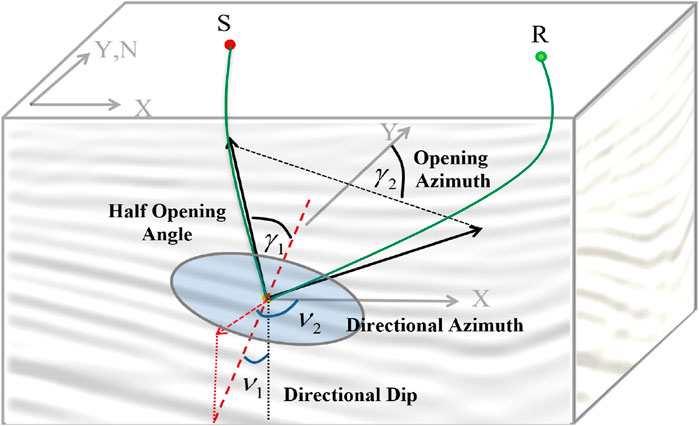
Figure 1. The geometric relationship of subsurface propagation angles. M represents the local reflection plane;
The azimuth angle and reflection angle of the subsurface imaging point can be determined using Equation 4:
where
The angle domain source and receiver wavefields can be derived by incorporating the propagation direction. The imaging condition in the angle domain is expressed as follows:
where
According to the angle domain imaging conditions given by Equation 5, imaging result is performed indiscriminately for all angles, which may result in low wavenumber interference. Therefore, an angle filter can be introduced into Equation 6:
where
According to Snell’s Law, for a locally planar reflection surface, the relationship between the incident angle, the scattered angle, and the inclination angle of the reflection surface is illustrated in Figure 2. The observation coordinate system can be rotated into alignment with the target coordinate system using Equation 8:
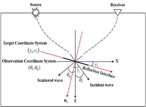
Figure 2. The Target Coordinate System and Observation Coordinate System. The red lines represent the two base vectors of the observation system’s coordinate system; the blue lines represent the two base vectors of the target system’s coordinate system; the thick black lines represent the local reflection interface.
The Equation 7 can be further modify to Equation 9:
Full-azimuth ADCIGs depict the relationship between the local incidence angle, azimuth angle, and spatial position of imaging points. They are widely acknowledged as artifact-free gathers and are suitable for azimuthal stacking imaging and migration velocity analysis.
The local imaging matrix, depicted in Figure 3, is derived by merging all partial images from Equation 5. By integrating the azimuth and reflection angles along the main diagonal, full-azimuth ADCIGs can be extracted. To mitigate discrepancies between the computed angle and the sampling angle, Gaussian filtering is employed to facilitate uniform interval angle sampling, thereby improving the signal-to-noise ratio. The formula for mapping full-azimuth ADCIGs is as follows:
where
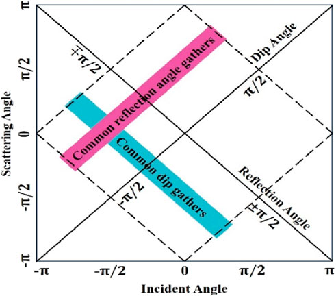
Figure 3. The local imaging matrix. The horizontal and vertical coordinates represent the incident angle and the scattering angle, respectively; the main diagonal corresponds to the reflection angle, and the secondary diagonal corresponds to the dip angle.
With the advancement of wide-azimuth and high-density acquisition technologies, it has become standard practice in 3D exploration to fire tens of thousands of shots and receive tens of thousands, or even hundreds of thousands, of traces within a single work area. For reverse time migration, each spatial point necessitates thousands of time steps of wavefield extrapolation, leading to an immense computational burden.
For full-azimuth angle domain reverse time migration, the computational demands are even more substantial due to the additional requirement of solving for both the reflection angle and azimuth angle at the subsurface imaging points. Consequently, the implementation of CPU and GPU collaborative parallel algorithms (illustrated in Figure 4) can be utilized to enhance computational efficiency. Initially, the GPU is employed to compute imaging values and determine subsurface propagation angles, while storing the imaging data and angle field data. Once the calculations are completed, these two types of data are transferred back to the CPU for reorganization into angle gathers.
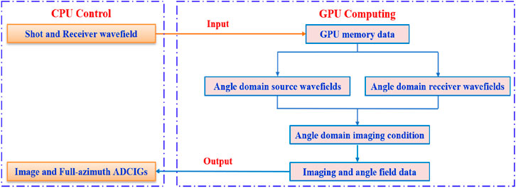
Figure 4. Collaborative acceleration framework of CPU and GPU.
Reverse time migration is a comprehensive wavefield imaging technique that demands substantial storage resources. In particular, the memory requirements for full-azimuth reverse time migration surpass those of conventional reverse time migration by over a hundredfold, thereby imposing more stringent demands on computer hardware.
Within the RTM imaging algorithm framework, once the azimuth and reflection angles are computed in the compute nodes, we can harness the properties of floating-point data. By storing the positive or negative status of the angles in the sign bit, compressing and encoding the reflection angle in the exponent bit, and similarly compressing and encoding the azimuth angle in the mantissa bit. This method enables the storage of two angles within a single floating-point character, leading to memory savings, enhanced I/O efficiency, and the added advantage of data encryption. Upon transmission of the data back to the main node, it undergoes decoding based on the compressed encoding scheme, is converted back to azimuth and reflection angle data, and subsequently, the imaging values are refined. The detailed implementation process is illustrated in Figure 5.
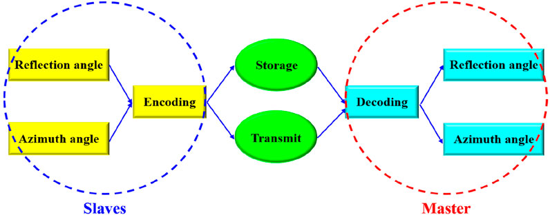
Figure 5. The implementation process of data compression technology based on encoding and decoding.
In this section, we use the Depression model to test the effectiveness of the proposed method. The model consists of a depression and two horizontal layers, as depicted in Figure 6. It features a grid size of 201 × 201 × 201, with grid spacings of 20m, 20m, and 15m, respectively. The seismic records encompass 441 shots, all of which are fully received. The recording duration is 3.0s, with a sampling interval of 1 m. The azimuth angle spans from 0° to 180°, with intervals of 45°, while the reflection angle ranges from 0° to 60°, with intervals of 1°.
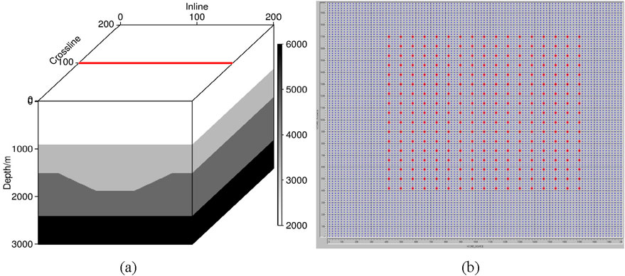
Figure 6. The velocity and observation systems of Depression model: (a) velocity field; the red line represents the location of the target line; (b) observation systems; the red dots and blue dots represent the distribution of shot points and receiver points, respectively.
The migration profile and full-azimuth ADCIGs of Line 101 are shown by Figure 7. The imaging result exhibits an excellent match with the precise model, clearly showing the depression and the two horizontal layers. Additionally, full-azimuth ADCIGs extracted at CDP 101 reveal the interaction between seismic waves and reflective interfaces in the angle domain. The gather appears generally flattened, and the variation in energy across azimuth and reflection angles is relatively consistent.

Figure 7. Trial calculation results of Line 10l: (a) the migration profile; (b) full-azimuth ADCIGs extracted at CDP 101. The rose chart represents different azimuth angles.
The SEG/EAGE salt model is recognized as an international standard for three-dimensional geological modeling. The top of the salt dome has complex structures, with small fault zones developed in the upper part. It encompasses various characteristics beneath the salt dome and poses high requirements for imaging algorithms, making it suitable for verifying the correctness and effectiveness of algorithms. The model grid size is 451 × 451 × 251, with grid spacings of 30 m, 30 m, and 20 m, respectively. The synthetic seismograms consist of 3,333 shots, each containing 4,001 time sampling points at an interval of 2 m (as shown by Figure 8). The azimuth angle range is 0°–180°, with intervals of 45°, and the reflection angle range is 0°–60°, with intervals of 2°.
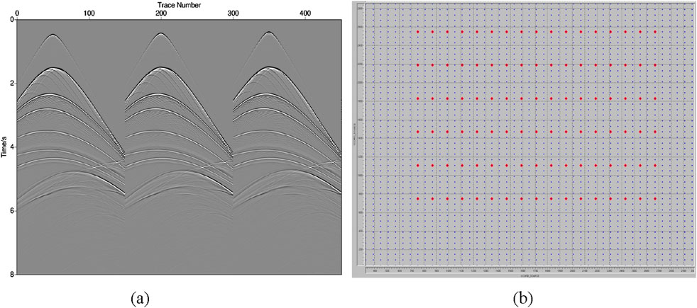
Figure 8. The shot record and observation systems of Salt model: (a) shot record; (b) observation systems; the red dots and blue dots represent the distribution of shot points and receiver points, respectively.
Figure 9 presents the velocity field and full-azimuth reverse time migration profile of Line 200. It can be observed that full-azimuth reverse time migration effectively characterizes the top and bottom interfaces of the salt body. Additionally, the small fault zone in the upper part of the salt and the complex structure below the salt are also clearly depicted. To further validate the algorithm, full-azimuth ADCIGs are extracted at CDP 211 and 371 (as shown in Figure 10). The gathers are accurately positioned and generally exhibit a flattened state, with events appearing more continuous and focused.
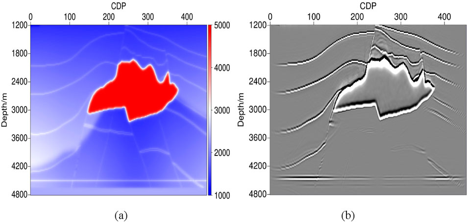
Figure 9. Trial calculation results of Line 200: (a) velocity field; (b) full-azimuth reverse time migration profile.
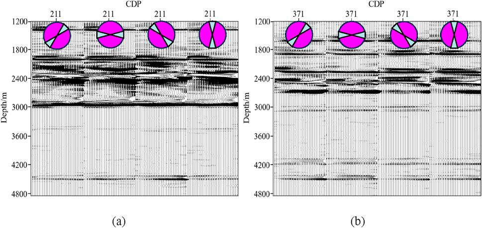
Figure 10. Full-azimuth ADCIGs extracted at: (a) CDP 211; (b) CDP 371. The rose chart represents different azimuth angles.
Figure 11 illustrates the stacked profiles with varying azimuth angles, highlighting the inconsistent energy distribution across different structures in various azimuthal sections. By comparing the azimuthal stacked profiles, it is clear that the fault in the bottom left corner exhibits the strongest energy at the azimuth of 135° (as indicated by the red arrow), and its strike lies within this range. Based on this characteristic, the elimination of imaging artifacts can also be carried out.
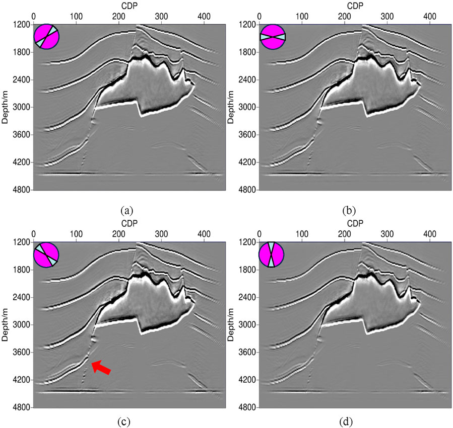
Figure 11. Stacked profiles with different azimuth angle: (a) stacked profile of 0–45° azimuth angles; (b) stacked profile of 46–90° azimuth angles; (c) stacked profile of 91–135° azimuth angles; (d) stacked profile of 136–180° azimuth angles. The rose chart represents different azimuth angles.
The Comparison of computational efficiency and memory consumption is shown by Table 1. It is evident that the efficiency can be improved by 40% and memory usage can be optimized by 30% after optimization, greatly enhancing the practicality of the method.
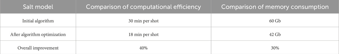
Table 1. Comparison of computational efficiency and memory requirements between the initial algorithm and the optimized algorithm.
With the development of wide azimuthal and high-density acquisition technology, the seismic data contains abundant media information, providing higher demands for full-azimuth imaging technology. Based on different theories, full-azimuth imaging technology is mainly divided into ray-tracing algorithms and wave-propagation algorithms. Paradigm’s ES360 imaging technology is the representative ray-tracing algorithm that demonstrates the advantages and potential of full-field imaging (Koren and Ravve, 2011; Inozemtsev et al., 2015; Inozemtsev et al., 2017). This method exhibits high computational efficiency and flexibility. However, it is constrained by the inherent limitations of ray theory, resulting in theoretical deficiencies when dealing with complex structures and regions with strong lateral velocity variations.
The reverse time migration, based on the numerical solution of the wave equation, is capable of accurately describing the propagation patterns of seismic waves, making it the representative imaging algorithm in the wave-propagation algorithms (Baysal et al., 1983). The theoretical challenge emphasized for the full-azimuth reverse time migration is the accuracy of propagation angle calculations in complex wavefield scenarios. The Poynting Vector Method, a widely applied algorithm in the industry, offers high computational efficiency and angular resolution (Yoon and Marfurt, 2006; Zhang et al., 2010; Yan and Dickens, 2016). However, it has issues with local computational instability and inaccuracy. The Wavefield Decomposition Method effectively enhances the calculation accuracy of propagation angles in complex wavefield scenarios (Wu et al., 2021). However, it requires more computational resources and storage capacity, placing higher demands on computer hardware. This paper, based on the conventional Poynting algorithm, introduces the amplitude and phase gradients of the wavefield to perform iterative solutions for the propagation vector. This approach not only effectively enhances the stability and accuracy of the algorithm, but also offers high computational efficiency, making it more suitable for large-scale data.
The practical application of full-azimuth reverse time migration is hindered by computational demands and storage requirements, posing a significant bottleneck. Consequently, existing research predominantly focuses on extracting the reflection angle, often neglecting azimuthal information (Wang et al., 2013; Zhang, 2014). In this paper, we present a novel approach that combines a CPU-GPU collaborative parallel algorithm with encoding-decoding-based data compression technology. This integration significantly enhances computational efficiency and optimizes memory utilization, allowing us to extend the angle domain algorithm to full-azimuth. By fully harnessing the energy differences across various azimuths, our method effectively eliminates imaging artifacts in complex media, leading to a more accurate and reliable restoration of true subsurface geological structures.
This paper develops a full-azimuth angle domain reverse time migration technology, which can fully utilize subsurface azimuth and reflection angle information to output high quality imaging profiles and full-azimuth gathers. Furthermore, we have devised an iterative approach to determine the propagation vector, leveraging the amplitude and phase gradients of the wavefields. This method offers enhanced stability and accuracy compared to the conventional Poynting vector algorithm. Meanwhile, through the using of CPU/GPU collaborative parallel computing technology and data compression technology based on encoding and decoding, the computational and storage bottlenecks faced by full-azimuth imaging have been effectively addressed, enhancing the practicality of the algorithm. In the future research, we will focus on the impact of illumination issues among different azimuths and velocity errors on the accuracy of gathers.
The raw data supporting the conclusions of this article will be made available by the authors, without undue reservation.
NQ: Methodology, Writing–original draft, Writing–review and editing. JX: Methodology, Writing–original draft, Writing–review and editing.
The author(s) declare that financial support was received for the research and/or publication of this article. This research is jointly supported by the special funding of Mountain Tai industry leading talent project (No. tscx202312059), Research and Development Project of Sinopec (Grant No. P23050, Grant No. P24144).
Thanks to the editorial department teachers and reviewers for this article given guidance and suggestions!
Authors NQ and JX were employed by the Shengli Geophysical Research Institute of Sinopec.
The authors declare that this study received funding from Sinopec. The funder had the following involvement in the study: seismic data, computing resources, and publication permissions.
The authors declare that no Generative AI was used in the creation of this manuscript.
All claims expressed in this article are solely those of the authors and do not necessarily represent those of their affiliated organizations, or those of the publisher, the editors and the reviewers. Any product that may be evaluated in this article, or claim that may be made by its manufacturer, is not guaranteed or endorsed by the publisher.
Baysal, E., Dan, D. K., and Sherwood, J. W. C. (1983). Reverse time migration. Geophysics 48 (11), 1514–1524. doi:10.1190/1.1441434
Hill, N. R. (2001). Prestack Gaussian-beam depth migration. Geophysics 66 (4), 1240–1250. doi:10.1190/1.1487071
Inozemtsev, A., Koren, Z., and Galkin, A. (2015). Noise suppression and multiple attenuation using full-azimuth angle domain imaging: case studies. First Break 33 (6). doi:10.3997/1365-2397.33.6.81553
Inozemtsev, A., Koren, Z., and Galkin, A. (2017). Applying full-azimuth depth imaging in the local angle domain to delineate hard-to-recover hydrocarbon reserves. First Break 35 (12). doi:10.3997/1365-2397.35.12.90804
Koren, Z., and Ravve, I. (2011). Full-azimuth subsurface angle domain wavefield decomposition and imaging Part I: directional and reflection image gathers. Lead. Edge 76 (1), S1–S13. doi:10.1190/1.3511352
Miller, D., Oristaglio, M., and Beylkin, G. (1987). A new slant on seismic imaging: migration and integral geometry. Geophysics 52 (7), 943–964. doi:10.1190/1.1442364
Ravve, I., and Koren, Z. (2011). Full-azimuth subsurface angle domain wavefield decomposition and imaging: Part 2—local angle domain. Geophysics 76 (2), S51–S64. doi:10.1190/1.3549742
Symes, W. W. (2007). Reverse time migration with optimal checkpointing. Geophysics 72 (5), 213–221. doi:10.1190/1.2742686
Wang, B. L., Gao, J. H., Chen, W. C., and Zhang, H. L. (2013). Efficient extraction of angle gathers using Poynting vector in reverse time migration. Chin. J. Geophys. 56 (01), 262–268. doi:10.6038/cjg20130127
Wu, C. L., Wang, H. Z., Feng, B., and Sheng, S. (2021). Research on extraction method of reverse time migration angle gather based on CLG optical flow and wavefield decomposition. Chin. J. Geophys. 64 (04), 1375–1388. doi:10.6038/cjg2021O0088
Yan, J., and Dickens, T. A. (2016). Reverse time migration angle gathers using Poynting vectors. Geophys. J. Soc. Explor. Geophys. 81, S511–S522. doi:10.1190/geo2015-0703.1
Yoon, K., and Marfurt, K. J. (2006). Reverse-time migration using the Poynting vector. Explor. Geophys. 37 (1), 102–107. doi:10.1071/eg06102
Yue, Y. B. (2011). Study on Gaussian beam migration methods in complex medium. Qingdao: China University of Petroleum East China.
Zhang, Q. (2014). RTM angle gathers and specular filter (SF) RTM using optical flow. in SEG Technical Program Expanded Abstracts 2014. Society of Exploration Geophysicists, 3816–3820. doi:10.1190/segam2014-0792.1
Keywords: reverse time migration, wavefields gradient, propagation vector, local imaging matrix, full-azimuth angle domain common imaging gathers
Citation: Qin N and Xiao J (2025) Full-azimuth angle domain reverse time migration. Front. Earth Sci. 13:1552795. doi: 10.3389/feart.2025.1552795
Received: 29 December 2024; Accepted: 07 March 2025;
Published: 20 March 2025.
Edited by:
Jidong Yang, China University of Petroleum (East China), ChinaReviewed by:
Feilong Yang, Xi’an Shiyou University, ChinaCopyright © 2025 Qin and Xiao. This is an open-access article distributed under the terms of the Creative Commons Attribution License (CC BY). The use, distribution or reproduction in other forums is permitted, provided the original author(s) and the copyright owner(s) are credited and that the original publication in this journal is cited, in accordance with accepted academic practice. No use, distribution or reproduction is permitted which does not comply with these terms.
*Correspondence: Jianen Xiao, MzU5OTc0MTE3QHFxLmNvbQ==
Disclaimer: All claims expressed in this article are solely those of the authors and do not necessarily represent those of their affiliated organizations, or those of the publisher, the editors and the reviewers. Any product that may be evaluated in this article or claim that may be made by its manufacturer is not guaranteed or endorsed by the publisher.
Research integrity at Frontiers
Learn more about the work of our research integrity team to safeguard the quality of each article we publish.