 Linpo Shi
 Meng Xing2
- 1State Key Laboratory for Geomechanics and Deep Underground Engineering, China University of Mining and Technology, Xuzhou, China
- 2Gu-Cheng Coal Mine of Shanxi Lu’an Mining Group, Changzhi, Shanxi, China
- 3School of Architecture and Civil Engineering, Anhui Polytechnic University, Wuhu, Anhui, China
The freezing method is often adopted to reinforce the surrounding formation during deep foundation pit excavations. According to the traditional theory of freezing wall design in coal mine construction engineering, it is necessary to design a continuous, thicker freezing wall. The multi-turn combination cylinder freezing wall structure can optimize the freezing design, but the strength and stability of the wall structure are theoretical and technical issues that urgently need to be researched and solved. In this work, the mechanical characteristics of frozen walls of multi-coil composite cylinders are analyzed using theoretical methods. Based on the elastoplastic theory, the freezing wall of a multi-turn combined cylinder is simplified to an axisymmetric plane problem, and the theoretical calculation model of the freezing expansion force, generated by the freezing process, around the perimeter of a circular hole under an axisymmetric plane strain model is developed. The corresponding variable model for the displacement immobility point of the freezing circle is proposed, and the progressive formation of the freezing wall is achieved through iterative calculations. The theoretical calculation formulas for the freezing force generated by the freezing process around a circular hole under the plane strain model are derived considering the gradual formation process of freezing expansion. The results of the research provide the theoretical basis for the construction of permafrost deep foundation pit engineering.
1 Introduction
With the country’s implementation of the Western development strategy, more and more tunnels have been built in complex mountainous areas (Fu et al., 2024; Ji et al., 2024; Zhang T. et al., 2024), especially in cold regions. Unfortunately, low temperatures, which may be lower than −40°C, bring a series of problems for geotechnical engineering, such as frost heaving. This significantly affects the physical and mechanical behaviors of the surrounding rock and lining structure. To ensure safety, the frost heaving acting on the lining structure should be determined first.
Numerous studies on tunnel excavation in cold regions have been carried out in the last few years. The results show that the main cause for frost heave is water migration and volume expansion of water-rich geotechnical materials. Some scholars have proposed analytical solutions for circular openings using the Laplace transform method. Ji et al. (2017) investigated the frost heaving-induced pressure of frost-susceptible silty clay under various restraints and thermal gradients. The results indicate that the frost heaving-induced pressure decreases rapidly with the relaxation of restraints, while this downward trend slows down as the frost heaving ratio increases.
The constitutive equation directly determines the displacement direction induced by frost heaving behavior, which is the main factor of frost heave force. In a previous study, the surrounding rock was considered to undergo isotropic expansion during the freezing process, where the elastic modulus of frozen rock was assumed to deteriorate. However, this is obviously different from the actual conditions. Researchers assumed the average radius of the frozen region as zero displacement position for circular tunnels. Hence, the frost heaving displacement point inside the tunnel and that of the outer part move toward infinity. Based on the finite element method, Feng et al. (2017) proposed a supplemental equation relating the frost heaving force, frost heaving displacement, and the inner and outer radii. Considering the predominant frost heaving along the heat conduction direction, Zhang et al. (2023) derived analytical solutions for the frost heaving force for circular tunnels, in which isotropic expansion is only a particular case.
Moreover, rock-like materials generally manifest progressive failure characteristics after the peak strength is reached during the loading process, known as strain-softening behavior (Shi et al., 2023a; Shi et al., 2023b; Shi et al., 2023c; Zhang et al., 2023; Zhang W. et al., 2024; Gu et al., 2024). Considering the strain-softening behavior, Lee and Pietruszczal (2008), Wang et al. (2010), and Zhang et al. (2012) studied the stress and displacement of circular tunnels using numerical and analytical methods. These studies show that the volume plastic strain gradually increases due to the formation of macro cracks (Jing et al., 2020; Wu et al., 2020; Wu et al., 2022; Wu et al., 2024; Yuan et al., 2024), so the porosity of the surrounding rock should depend on both its initial porosity and the volume plastic strain. Moreover, the expansion of frost-affected rock mass is induced by the volume expansion of water during its transition from liquid to solid. In other words, the linear coefficient of linear expansion should be considered a function of volume plastic strain. On the other hand, the freezing of the surrounding rock is a progressive process. When the constitutive model is related to the geometry of the frozen region, the frost heaving force and displacement would show significant differences with the assumption of the freezing region forming simultaneously. However, existing research studies have demonstrated a relative lack of focus on this particular area. In this paper, based on the elastoplastic theory, the progressive formation process of frost heave is considered. The theoretical formula for the freezing force generated by the freezing process around a circular hole under the plane strain model is derived to provide guidance for the design and construction of freezing walls in ultra-large diameter deep foundation pit projects.
2 Problem description
Figure 1 shows a circular tunnel of radius R0 excavated in an infinite isotropic rock mass subject to a hydrostatic stress p0. The linear structure, with a thickness of t, is immediately applied after excavation with a deformation allowance of u0. Once the supporting pressure provided by the linear structure is lower than the critical value pc, a plastic region with a radius Rp is developed around the tunnel, and then, the water fills the cracks of the plastic rock mass. The frost rock mass is progressively formed from the excavation surface to the inner during heat conduction. The radius of the frost region is Rf, which can be determined using the field temperature test of the surrounding rock. In this study, the frost behavior is assumed after the excavation effect, and the frost heave does not change the failure state of the surrounding rock, so the total stress is composed of excavation force and frost heave stress.
Figure 1. Calculation mechanical model.
2.1 Governing equations
For the axisymmetric plane strain problem, the stress should satisfy the following equilibrium equation without considering the body force:
The failure state of the surrounding rock is governed by the yield criterion. The nonlinear Hoek–Brown (HB) criterion, which takes the influence of the geological strength index (GSI) into account, is widely used for geotechnical engineering. In the polar coordinate, the generalized HB criterion in the ith annulus can be expressed as
where
The strain–displacement compatibility equation can be expressed as follows:
For the elastoplastic problem, the total strain of plastic rock mass is composed of the elastic strain and plastic strain, i.e.,
The elastic strain should satisfy Hooke’s law, and it can be expressed as Equation 5:
For the geotechnical material, the M-C plastic potential function is commonly used. The relation between the radial and circumferential plastic strain can be obtained as Equation 6:
where β = (1 + sinψ)/(1-sinψ) and ψ is the dilation angle.
Theoretically speaking, the frost heave is mainly induced by the decrease in the inner radius of the frost region. When a free frost heave happens for a circular annulus, the axial length increases and the inner radius decreases, so there exists a zero displacement radius
where
2.2 Evolutional law of parameters
With respect to the strain-softening rock mass, the plastic shear strain
where ω denotes any one of m, s, σc, a, ψ, E, and v in the ith annulus; ωp and ωr correspond to the elastic and residual state values, respectively; and γp* is the critical plastic shear strain, beyond which the surrounding rock transitions into the residual state.
It is important to note that the frost heave mainly occurs due to the expansion of water when its temperature decreases below 0. Therefore, the porosity ratio depends on the frost heave coefficient for the water-rich surrounding rock. For the strain-softening surrounding rock, the macro cracks gradually increase once the crack initiation stress is reached. These cracks are much larger than the potential pores of intact rock, so the frost heave ratio also depends on the failure degree, which can be described by the volume plastic strain for strain-softening rock mass. For the plane strain problem, the volume plastic strain equals the plastic shear strain due to the zero plastic strain for the intermediate strain when the M-C plastic potential function is employed. In this study, the expansion coefficient is assumed to be linear and related to the plastic shear strain (Equation 9):
where ξ is the frost heave coefficient of the surrounding rock; ξ0 is the frost heave ratio of the elastic rock; and b is a fitting coefficient.
3 Solutions of stress and displacement
Since the frost heave ratio depends on the failure degree, the stress and displacement induced by excavation should be solved first. Subsequently, a methodical approach involving a progressive frost heave process, layer by layer, is employed to derive theoretical solutions for the stress and displacement within the structure.
3.1 Stress and displacement induced by excavation
On the elastic–plastic boundary, the stress and strain under plane strain conditions can be easily obtained by use of the peak strength parameters and the initial in situ stress p0. The explicit analytical expression of σk can only be obtained when a = 0.5 (Park and Kim, 2006):
For the common condition of a > 0.5, only the implicit calculation equation of Equation 10 can be obtained. However, it can be easily calculated using the Newton method with an initial value of Equation 11.
Then, the stress and strain at the elastic–plastic boundary can be obtained as Equations 12, 13:
For the elastoplastic problem of plane strain circular openings, the radial stress gradually increases from the supporting pressure σ0 to the initial stress p0. By dividing the plastic region into n annuli with equal increments, the radial stress increment between the inner and outer regions can be obtained as Equation 14:
For the strain-softening surrounding rock, the strength and deformation should obey the evolutional laws with the plastic shear strain. Meanwhile, the plastic shear strain also depends on the strength and deformation parameters. The difficulty is that they should be compatible at any point, which leads to a non-analytical solution. However, if the annulus number is large enough, the thickness of each annulus would be significantly small. The increment in shear plastic strain at the inner and outer radii for each annulus would also be significantly less. In this condition, the plastic shear strain at the outer radius can be employed to represent the annulus’s softening index. Then, the strength and deformation parameters of the ith annulus can be determined once the shear plastic strain at r = Ri + 1 for the (i + 1)th annulus is obtained. Using the yield criterion of Equation 2, the circumferential stress at r = Ri+1 can be expressed as follows:
Then, the circumferential stress increment can also be approximated as
The equilibrium equation of Equation 1 can be expressed differentially by representing the variables with average values:
where ρi = Ri/Rp. Then, the dimensionless radius ρi can be explicitly expressed as
By using Hooke’s law, the compatibility equation can be reformulated as Equation 19:
When the average value of strain and H is employed, Equation 4 can also be reformulated in a differential way. Then, the circumferential plastic strain increment can be obtained as Equation 20:
where ki = (1 + sinψi)/(1-sinψi).
Then, the radial plastic strain, shear plastic strain, volume plastic strain, and total strain at Ri-1 are updated as
All the stresses and strains can be calculated recursively until the radial stress decreases to the supporting pressure σ0. The radius and displacement of the plastic region can be obtained as follows:
The real supporting pressure provided by the lining structure due to the displacement of the excavation surface can be easily obtained
where
If the real supporting pressure σL equals the assumed supporting pressure σ0, the calculation results would be the actual solution. Otherwise, the assumed supporting pressure can be easily calculated using the secant method or dichotomy method.
3.2 Stress and displacement induced by frost heaving
Without loss of generality, the frost front radius Rf is assumed to be larger than the plastic radius Rp. The plastic region uses the same partition method as strain-softening behavior, and the region Rp < r < Rf is divided into m annuli. The elastic stress and displacement of the outer annulus induced by frost heaving can be easily obtained as follows:
For the annulus in the frost region, the closed-form analytical solution for the stress and displacement can be uniformly expressed as follows:
where
Using the displacement continuum condition of the adjacent annulus, the radial stress induced by frozen heaving can be recursively expressed as Equations 30, 31:
For the sake of safety, the lining structure is only allowed to work in the elastic state. The stress and displacement can also be obtained as Equation 32:
3.3 Calculation process
To calculate the frost heave force, the failure degree of the surrounding rock should be determined first. The detailed calculation flow is listed in the following steps:
Step 1: Input data of material properties, geometry, and the section number k and then space the radial stresses into k sections using Equation 1.
Step 2: Calculate the dimensionless radius ρi using Equations 22, 23 of the ith annulus, and then determine the material parameters of the adjacent inner annulus by Equations 10, 11 using the radial stress at ρ = ρi.
Step 3: Judge whether the shear plastic strain satisfies the critical state using Equation 21. If not, i = i-1, and go to step 2, or go to step 4.
Step 4: Calculate the dimensionless radial stresses and displacement of plastic rock mass using Equations 15, 16, 24, 25 for M-C rock mass and Equations 17, 18, 28, 29 for H-B rock mass;
Step 5: Calculate the shear plastic strain using Equations 26, 30 for M-C and H-B rock mass, respectively, and then determine the material parameters of the adjacent inner annulus using Equations 10, 11;
Step 6: Repeat step 5 until the innermost annulus; calculate the residual radius using Equation 27; and output the results.
4 Examples
4.1 Verifications for strain-softening rock mass
To verify the reliability of the analytical solution, the normally strained softened rock body is considered the research object, where the coefficients and friction angles are plastic strain functions. The typical input data used by Alonso et al. (2003), Lee and Pietruszczak (2008), and Wang et al. (2010) are employed, and the input data are visualized in Figure 2 and provided in Table 1. The outer radius of the elastic region is 1000R0. The GRC curves are shown in Figure 2. The relative error between the two analytic solutions is relatively small, at only 1.42%. Moreover, it is approximately consistent with the analytical results of Zhang et al. (2012). So, the solutions are in good agreement with both the numerical and analytical results.
Figure 2. Ground response curve of surrounding soils induced by excavation.

Table 1. Values of the calculated parameters.
4.2 Analysis of freezing and expansion forces in excavated tunnels
Once the excavation of the cavern is completed, the stresses and deformations in the surrounding geotechnical medium produce secondary adjustments. However, artificial or natural freezing behavior occurs after the adjustment of surrounding rock stresses and deformations, and this section exclusively examines the freezing forces generated by freezing around the perimeter of the media. According to the mechanical properties of commonly utilized concrete, the elastic modulus EL = 28 GPa, Poisson’s ratio vL = 0.2, and the frost heaving coefficient of the medium are set as 0.055°C−1. In the analysis of the freezing force of the lining structure due to frost heave, it is generally assumed that there is no displacement in the frozen zone due to frost heave behavior at the radius of the midpoint. This assumption serves as a supplementary equation for further calculating the freezing force exerted on the lining structure. However, the freezing behavior of geotechnical media develops gradually in stages, with each expansion of the frozen zone being constrained. It is more reasonable to analyze the assembly form caused by the expansion of the newly generated frozen zone, which means that it is considered that the displacement immobility point after the freezing and expansion of the newborn frozen zone is generated within the scope of the region. The effect of internal radial stress after media freezing under different ground freezing coefficients is illustrated in Figure 3. In this case, the maximum freezing expansion within the medium occurs within the frozen zone, and the freezing expansion force imposed on the lining structure is not at the point of maximum radial stress. When the coefficients of linear expansion for media freezing expansion were 0.0055, 0.0035, and 0.0015, the maximum radial stress induced by freezing expansion within the media was recorded as 18.55 MPa, 11.80 MPa, and 5.06 MPa, respectively. Conversely, the lining structure was exposed to stresses of only 10.62 MPa, 6.76 MPa, and 2.90 MPa, which are 57.26% of the maximum radial frost heave stress.
Figure 3. Distribution of the freezing force inside the medium for different freezing coefficients.
Figure 4 illustrates the influence of different freezing linear expansion coefficients of the medium on the freezing and expansion forces applied to the lining structure. It can be observed that the freezing force increases linearly with an increase in the freezing linear expansion coefficient. Specifically, each unit increase in the linear expansion coefficient results in a 1940 MPa surge in the freezing force sustained by the masonry structure. The freezing force on the masonry structure increases by 1935.83 MPa per unit coefficient of linear expansion. Therefore, the media freezing coefficient has a significant effect on the freezing force of the lining structure. Moreover, lining structures with different resistance characteristics generate distinct freezing and expansion forces, and the typical frost heave force characteristics of lining structures with different lining thicknesses are shown in Figure 5. As the thickness of the lining increases, the freezing force acting on the structure exhibits a nonlinear increase trend, and the growth rate of the freezing force decreases gradually with an increase in thickness. When the thickness of the lining structure increased from 10 cm to 50 cm, there was a corresponding increase in the freezing force exerted on it, from 2.90 MPa to 7.55 MPa, with a growth rate of 160.34%. Therefore, for weak strata, a thicker lining structure is often required to ensure the stability of the surrounding geotechnical body. If this type of formation structure develops frost heave behavior, the frost heave hazard tends to be greater than that in hard rock formations.
Figure 4. Frost heave of lining under different linear strain coefficients.
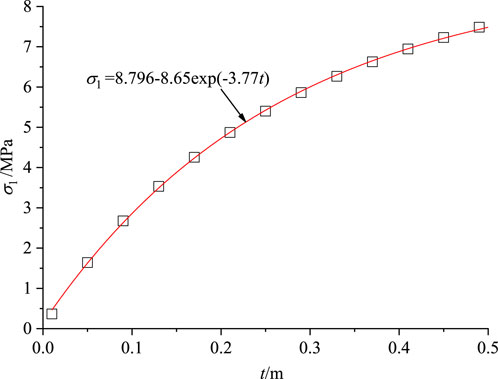
Figure 5. Frost heave of lining with different lining thicknesses.
4.3 Discussion
This paper conducts a theoretical analysis and research on the mechanical properties of multi-turn composite cylinder freezing walls. In future research, we will apply the theoretical structures obtained in this paper to practical engineering. We plan to use the temperature–stress field sequential coupling computational functionality of ANSYS finite element analysis software to establish a plane strain model of frozen soil interspersed with unfrozen soil and an axisymmetric vertical excavation model. This paper investigates the mechanical characteristics of single-, two-, and three-ring combined cylinder freezing walls, respectively. The influence of freezing deformation, horizontal displacement of excavation, and equivalent stress and strain under different unfrozen soil conditions is analyzed. The research results can provide a theoretical basis for the design and construction of freezing walls in super-large diameter deep foundation pit projects and support the numerical simulation of multi-turn combined cylinder freezing walls. The ultimate aim is to achieve a safe, reliable, economical, rational, and environmentally friendly design and construction technology for multi-ring composite pipe-freezing walls.
5 Conclusion
In this paper, a theoretical calculation model of the freezing expansion force generated by the freezing process around a circular hole under the axisymmetric plane strain model was developed. A corresponding variable model for the immobile point of the freezing circle displacement was proposed, and the progressive process of frost heave was realized through calculations. The conclusions drawn from this work are listed as follows:
(1) A variable model for the displacement of the frozen ring’s fixed point is proposed, taking into account the progressive formation process of freezing and expansion around the cavern. The theoretical formula for calculating the freezing force generated by the freezing process around a circular hole under the plane strain model is derived.
(2) The maximum frost heave force point of the medium around the circular hole usually occurs at a certain point inside the medium. The freezing force on the lining structure tends to increase linearly with the medium’s expansion coefficient.
(3) The thicker the permanent building structure, the greater the freezing force it experiences when the ground freezes. This is highly detrimental to the practical construction using the freezing method.
Data availability statement
The original contributions presented in the study are included in the article/Supplementary Material; further inquiries can be directed to the corresponding author.
Author contributions
LS: data curation and writing–original draft. MX: formal analysis and writing–review and editing. PW: validation and writing–review and editing. KW: project administration and writing–review and editing. XC: software and writing–review and editing. HL: resources and writing–review and editing.
Funding
The author(s) declare that financial support was received for the research, authorship, and/or publication of this article. This work was supported by the Natural Science Research Project of Colleges and Universities in the Anhui Province (grant number 2022AH050963).
Conflict of interest
Authors MX, PW, and KW were employed by Gu-Cheng Coal Mine of Shanxi Lu’an Mining Group.
The remaining authors declare that the research was conducted in the absence of any commercial or financial relationships that could be construed as a potential conflict of interest.
Publisher’s note
All claims expressed in this article are solely those of the authors and do not necessarily represent those of their affiliated organizations, or those of the publisher, the editors and the reviewers. Any product that may be evaluated in this article, or claim that may be made by its manufacturer, is not guaranteed or endorsed by the publisher.
References
Alonso, E., Alejano, L. R., Varas, F., Fdez-Manin, G., and Carranza-Torres, C. (2003). Ground response curves for rock masses exhibiting strain-softening behaviour. Int. J.Numer. Anal. Methods.Geomech. 27 (13), 1153–1185. doi:10.1002/nag.315
Feng, Q., Liu, W. W., and Jiang, B. S. (2017). Analytical solution for the stress and deformation of rock surrounding a cold-regional tunnel under unequal compression. Cold Reg. Sci. Tech. 139, 1–10. doi:10.1016/j.coldregions.2017.04.003
Fu, Q., Yang, J., Gao, Y., Song, H., Liu, Y., et al. (2024). Combined blasting for protection of gob-side roadway with thick and hard roof. J. Rock Mech. Geotech. Eng. 16, 3165–3180. doi:10.1016/j.jrmge.2023.11.027
Gu, Q. X., Zhang, Q., Ye, S. Z., Dai, W., and Li, T. (2024). Shear fracture behavior and damage constitutive model of rock joints considering the effect of pre-peak cyclic loading. Theor. Appl. Fract. Mech. 130, 104289. doi:10.1016/j.tafmec.2024.104289
Ji, S., Lai, X., Cui, F., Liu, Y., Pan, R., and Karlovšek, J. (2024). The failure of edge-cracked hard roof in underground mining: an analytical study. Int. J. Rock. Mech. Min. Sci. 183, 105934. doi:10.1016/j.ijrmms.2024.105934
Ji, Y. K., Zhou, G. Q., Zhao, X. D., Wang, J., Wang, T., Lai, Z., et al. (2017). On the frost heaving-induced pressure response and its dropping power-law behaviors of freezing soils under various restraints Cold Reg. Sci. Tech. 142, 25–33. doi:10.1016/j.coldregions.2017.07.005
Jing, H. W., Wu, J. Y., Yin, Q., and Wang, K. (2020). Deformation and failure characteristics of anchorage structure of surrounding rock in deep roadway. Int. J. Rock. Mech. Min. Sci. 30, 593–604. doi:10.1016/j.ijmst.2020.06.003
Lee, Y. K., and Pietruszczak, S. (2008). A new numerical procedure for elasto-plastic analysis of a circular opening excavated in a strain-softening rock mass. Tunn.Underger. Sp. Tech. 23 (5), 588–599. doi:10.1016/j.tust.2007.11.002
Park, K. H., and Kim, Y. J. (2006). Analytical solution for a circular opening in an elastic-brittle-plastic rock. Int. J. Rock. Mech. Min. Sci. 43 (4), 616–622. doi:10.1016/j.ijrmms.2005.11.004
Shi, H., Chen, W., Zhang, H., and Lei, S. (2023b). A novel obtaining method and mesoscopic mechanism of pseudo-shear strength parameter evolution of sandstone. Environ. Earth Sci. 82, 60. doi:10.1007/s12665-023-10748-y
Shi, H., Chen, W., Zhang, H., Song, L., Ming, L., Wang, M., et al. (2023a). Dynamic strength characteristics of fractured rock mass. Eng. Fract. Mech. 292, 109678. doi:10.1016/j.engfracmech.2023.109678
Shi, H., Zhang, H., Chen, W., Song, L., and Li, M. (2023c). Pull-out debonding characteristics of rockbolt with prefabricated cracks in rock: a numerical study based on particle flow code. Comput. Part. Mech. 11, 29–53. doi:10.1007/s40571-023-00607-9
Wang, S. L., Yin, X. T., Tang, H., and Ge, X. R. (2010). A new approach for analyzing circular tunnel in strain-softening rock masses. Int. J. Rock. Mech. Min. Sci. 47 (1), 170–178. doi:10.1016/j.ijrmms.2009.02.011
Wu, J. Y., Jing, H. W., Gao, Y., Meng, Q. B., Yin, Q., and Du, Y. (2022). Effects of carbon nanotube dosage and aggregate size distribution on mechanical property and microstructure of cemented rockfill. Cem. Concr. Compos. 127, 104408. doi:10.1016/j.cemconcomp.2022.104408
Wu, J. Y., Jing, H. W., Yin, Q., Yu, L., Meng, B., and Li, S. (2020). Strength prediction model considering material, ultrasonic and stress of cemented waste rock backfill for recycling gangue. J. Clean. Prod. 276, 123189. doi:10.1016/j.jclepro.2020.123189
Wu, J. Y., Wong, H. S., Zhang, H., Yin, Q., Jing, H. W., and Ma, D. (2024). Improvement of cemented rockfill by premixing low-alkalinity activator and fly ash for recycling gangue and partially replacing cement. Cem. Concr. Compos. 145, 105345. doi:10.1016/j.cemconcomp.2023.105345
Yuan, W., Lai, X. P., Pei, Z. H., Sifan, L., Haibin, L., Wei, W., et al. (2024). Experimental and numerical study on the anchoring mechanism of an anchor bolt considering its lateral restraint effect. Rock Mech. Rock Eng. 57, 9617–9633. doi:10.1007/s00603-024-03981-9
Zhang, Q., Jiang, B. S., Wang, S. L., Ge, X. R., and Zhang, H. Q. (2012). Elasto-plastic analysis of a circular opening in strain-softening rock mass. Int. J. Rock Mech. Min. Sci. 50 (1), 38–46. doi:10.1016/j.ijrmms.2011.11.011
Zhang, T., Gao, Y., Liu, S. Y., Yu, J., and Zhang, C. (2024). Experimental and numerical studies of breakage and fractal characteristics of silica sands in high-pressure triaxial tests. Adv. Powder Technol. 35 (7), 104548. doi:10.1016/j.apt.2024.104548
Zhang, T., Zhang, C., Song, F. N., Zou, J. Q., Gao, Y., and Yang, W. H. (2023). Breakage behavior of silica sands during high-pressure triaxial loading using X-ray microtomography. Acta Geotech. 18 (10), 5195–5211. doi:10.1007/s11440-023-01866-9
Keywords: circular tunnel, strain-softening, frost heave force, cold region, theoretical calculation model
Citation: Shi L, Xing M, Wang P, Wang K, Cao X and Liu H (2025) Semi-analytical solution of frost heave force for circular tunnels in strain-softening rock mass. Front. Earth Sci. 13:1489419. doi: 10.3389/feart.2025.1489419
Received: 08 September 2024; Accepted: 02 January 2025;
Published: 25 February 2025.
Edited by:
Hao Shi, Anhui University of Science and Technology, ChinaReviewed by:
Zhongjing Hu, Xihua University, ChinaMing Min, Huazhong University of Science and Technology, China
Copyright © 2025 Shi, Xing, Wang, Wang, Cao and Liu. This is an open-access article distributed under the terms of the Creative Commons Attribution License (CC BY). The use, distribution or reproduction in other forums is permitted, provided the original author(s) and the copyright owner(s) are credited and that the original publication in this journal is cited, in accordance with accepted academic practice. No use, distribution or reproduction is permitted which does not comply with these terms.
*Correspondence: Linpo Shi, MTU0NTE0Nzc2QHFxLmNvbQ==