- 1Huaiyin Institute of Technology, Huai’an, China
- 2State Key Laboratory for Geomechanics and Deep Underground Engineering, China University of Mining and Technology, Xuzhou, China
Groundwater seepage can easily cause large deformation and fracture instability of the surrounding rock in deep roadways, and the coupling support of “yield-bolt-grouting” can effectively control the occurrence of such accidents. This paper takes the specific engineering geological conditions of deep water-enriched roadway as the research background, revealing the coupling control mechanism of yield-bolt-grouting. The mechanical characteristics of the yielding tube were determined using lab analysis, and an investigation was conducted for the support control mechanism of high-strength yielding bolts. The control mechanism of grouting reinforcement is summarized, and a comprehensive coupling control technology system of “yield-bolt-grouting” is proposed based on the rheological large deformation characteristics of the surrounding rock of deep water-enriched roadway, with high-strength yielding grouting anchor rods and high-strength yielding grouting anchor cables as the core. The on-site monitoring results indicate that this technology effectively controls the deformation of the surrounding rock. The research results provide new ideas and technical approaches for controlling the surrounding rock of deep water-enriched roadways.
1 Introduction
With the increasing intensity of coal resource mining, mining operations have gradually shifted towards deep strata. Compared with shallow roadway engineering, deep roadway engineering is located in a more complex geological and mechanical environment (Frenelus et al., 2022). In addition to bearing high geostress, many mining areas’ roadways are also deeply affected by groundwater seepage, such as Huaibei Mining Group and Feicheng Mining Group. etc. Under the long-term coupling effect of high geostress and strong permeable water pressure, the support and maintenance of such deep water-enriched roadways become extremely difficult, prone to disasters and accidents such as roof collapse, internal squeezing of the two sides, floor heave, and even sudden water inrush, posing a huge threat to the green, safe, efficient development and utilization of deep coal resources. Due to the presence of water, the stability mechanism of the surrounding rock in deep roadways becomes more complicated compared to that of general soft rock roadways. It is not only necessary to use various composite support methods to control the large deformation of the surrounding rock, but also to take reasonable measures to control its weakening process in order to improve its inherent load-bearing capacity. Du et al. (2021) proposed a rock mass joint control scheme of “anchor rod + short anchor cable + long anchor cable” to address the zoning deformation characteristics of weakly cemented coal gangue interlayered roof with rich water, achieving long-term stability of this type of roadway. Cheng et al. (2022) adopted a combined support scheme of bottom plate loosening blasting and grouting reinforcement, effectively controlling the bottom bulging deformation of deep structural stress rich soft rock roadways. This method can improve the stress environment of the surrounding rock of the roadway and enhance the deformation resistance of the bottom plate. Kabwe (2020) proposed a load indicator washer from the perspective of pre tensioning force of anchor rods, and verified it through numerical simulation, providing scientific guidance for the design and installation of anchor rods. Yin et al. (2020) proposed measures for controlling the large deformation characteristics of water rich soft rock roadway, including the combination of guidance and drainage for water control, as well as the use of full section and multiple methods for reinforcement and support. These measures effectively controlled the deformation of the surrounding rock. Based on the fluid structure coupling model, Zhang J. P. et al. (2022) used numerical simulation to study the control of the anchor cable (rod)-double arch truss coupling support technology in water-rich soft rock roadways, providing guidance for the support design of such roadways. Zhai et al. (2022) used indoor experiments, theoretical analysis, and numerical simulations to study the floor heave and its control mechanism of water rich soft rock roadways, and proposed a novel double-seal deep and shallow inverted bottom arch (DS-IBA) floor support technology, which effectively controlled the floor heave. Pinazzi et al. (2020) studied the bearing capacity of anchor rods under shear load, axial load, and two load combinations, providing a new approach for controlling the surrounding rock of deep water rich roadways from the perspectives of improving anchor bolts design and considering load conditions. Singh and Spearing (2021) established a new shear mechanics model for fully grouted anchor bolts, which can better predict the large shear deformation of anchor bolts and provide a new path for the design and control of roadway surrounding rock support. Wang et al. (2023) studied the mechanism of roof weakening in water-rich roadway of the western Qingyang mining area through on-site measurements, and proposed a technical method for controlling the stability of surrounding rock by adjusting the roadway section form and optimizing support parameters based on numerical simulation results. Lin et al. (2022) systematically analyzed the deformation characteristics of Jurassic soft rock roadways and optimized the original support scheme using theoretical analysis and numerical simulation. The results showed that optimizing the roadway section, thin spraying the roadway surface, optimizing the support components, and gradient support can effectively control the deformation of soft rock roadways.
The potential deformation of the surrounding rock in deep roadways under seepage is significant. In order to fully mobilize its self-supporting capacity, support structures that can absorb and transfer a large amount of energy should be selected to ensure the reasonable release of surrounding rock energy. There is still an uncontrollable deformation in the surrounding rock of the roadway, which requires the support system to have the function of yielding to alleviate uncontrollable deformation and reduce the damage of surrounding rock stress to the support structure. Komurlu et al. (2020) designed a new bolt head that can expand with increasing load in boreholes, which not only absorbs the energy of surrounding rock deformation but also significantly improves the anchoring force of grouted bolts. Lv et al. (2023) designed a yielding device for the anchoring system of large deformation roadways in deep mining through indoor experiments, numerical simulations, and field tests, which improved the overall stability of the anchoring system and solved the problem of large deformation support in deep roadways. Wang and Gao (2021) proposed the “multi-stage roof control and pressure relief support technology” to effectively control the deformation of the surrounding rock of the transportation roadway in the No. 4105 working face of Wenjiapo Mine in response to the deformation problem of large section mudstone roadway. Liu et al. (2020) proposed the joint control technology of “drilling pressure relief + yielding anchor rod” based on the engineering background of the track roadway in the deep horizontal 11 mining area of a certain mine, which solved the problem of continuous large deformation of high stress roadway in deep wells. Zhang J. G. et al. (2022) proposed a new prestressed yield bolt based on the engineering background of the Shangping roadway in Huafeng Coal Mine. They designed and applied a yielding support scheme, which not only prevented the anchor rod from breaking, but also controlled the long-term stability of the surrounding rock in the deep high stress roadway. Cao et al. (2023) systematically analyzed the control effect of a high-strength prestressed yielding bolt and cable on controlling open-off cut roadways in multiple stress concentration areas, using the No.23616 working face of the extremely close coal seam in Chaili Coal Mine as the engineering background, and revealed the mechanism of yielding support. Zou et al. (2024) studied the influence of amplitude on the performance of yielding tubes and proved the feasibility of using yielding tubes as energy absorbing components at the end of anchor rods, providing theoretical guidance for the stability control of surrounding rock in deep roadways.
As the surrounding rock of the roadway undergoes increased deformation, the load on the supporting structure correspondingly escalates. Eventually, the support may fail when it reaches its strength limit. Once this occurs, the extent of the fractured zone within the surrounding rock will sharply expand. However, by implementing proactive measures such as grouting and others to reinforce the roadway’s surrounding rock before the supporting mechanism fails, several benefits can be realized. This approach not only enhances the overall cohesion and internal friction angle of the surrounding rock, improving the overall strength of the rock mass but also establishes a robust foundation for bolts and cables, thereby enhancing the overall support effectiveness. Wu et al. (2022), Wu et al. (2024) studied the reinforcement effect of grouting materials from the aspects of external additives, microstructure, and mechanical properties, providing a scientific basis for the reinforcement of surrounding rock in water-rich roadways. Tahmasebinia et al. (2018) and Khaleghparast et al. (2023) respectively used numerical simulation and indoor testing methods to study the influence of impact load on the mechanical properties of full-length anchor bolts and end anchored anchor bolts, which showed that full-length anchoring can significantly improve the shear bearing capacity of the anchor body. Pan et al. (2020) developed a combined high-strength grouting anchor rod and conducted mechanical performance testing and on-site application, effectively controlling the deformation and failure of surrounding rock in deep roadways. Wang et al. (2024) have developed a combination of high-strength grouting anchor rods and high-strength hollow grouting anchor cables with advantages such as high strength and the ability to apply prestress. They have also verified on site that full-length prestressed bolt-grouting support can effectively enhance the self bearing capacity of weak and fractured surrounding rock, fully utilize the support potential of anchoring components, and limit the deformation and failure of roadway surrounding rock. Yang et al. (2023) proposed a joint support scheme consisting of multi-layer anchor bolt, bottom corner pressure relief and fractional grouting, with grouting as the core, to effectively control the stability of expansive soft rock roadways in the Kailuan mining area. Zhao et al. (2020) developed a composite support method for deep soft rock roadways using “shotcreting + grouting anchor bolt + anchor bolt + grouting anchor cable + anchor cable”, and verified its rationality and effectiveness through numerical simulation and on-site monitoring. Zhang et al. (2023) proposed a superposition community theoretical model and the superposition joint support scheme based on the occurrence conditions and failure characteristics of the transportation roadway in the west wing transportation roadway of Yuandian No. 2 Coal Mine, combined with the elastic-plastic and superposition arch theory, which includes “bolt (cable) + anchor net + anchor-grouting flexible bolt + shotcrete support”, effectively maintaining the stability of the roadway. Chen et al. (2023) proposed the stratified reinforcement ring support technology of “long cable-bolt-grouting” based on the engineering background of the large section whole coal cavern groups, effectively reducing the failure depth of surrounding rock and keeping the rock in a stable state. Fan et al. (2023) revealed the instability mechanism of the water-rich roadway through laboratory experiments and on-site monitoring, proposed a new optimized support design, including anchor rods, cables, metal mesh, shotcrete, and grouting, and provided specific support parameters, effectively controlling the deformation of the water-rich No.1044 return laneway in Taoyuan Coal Mine. Oppong et al. (2023) proposed using expansive grouting materials instead of traditional grouting materials, which can improve reinforcement efficiency and facilitate the stability of surrounding rock support systems, especially jointed and steeply inclined rock masses.
At present, scholars mainly focus on the control of deep roadway surrounding rock using anchor rod support or anchor injection support, and there are not many studies that combine the two organically. Therefore, this paper establishes corresponding mechanical models through compression tests of compression tubes and pull-out tests of compression anchor rods, and analyzes the mechanical characteristics of compression tubes and compression anchor rods, and elucidates the mechanism of compression anchor rod support. At the same time, combined with the grouting reinforcement mechanism, a support structure was developed and designed that integrates the yielding pressure technology with anchor grouting support, namely, high-strength yielding grouting anchor rods and high-strength yielding grouting anchor cables. A “yielding-bolt-grouting” coupling control technology system was proposed, which provides scientific guidance and technical support for the long-term stability control of surrounding rocks in deep water-enriched roadways.
2 Yield control mechanism of deep soft rock roadway
The primary purpose of the supporting system’s yield capability is to absorb and dissipate the uncontrollable deformation energy of the surrounding rock by utilizing its capacity to deform. This approach allows for the full and effective utilization of the self-bearing capacity of the roadway’s surrounding rock, ensuring the integrity and stability of the entire support system. Yielding bolt support technology proves to be the proficient solution for addressing support problems in deep soft rock roadways.
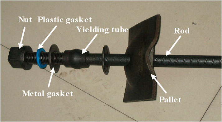
The high-strength yielding bolt maintains the integrity of the rod body, with a dedicated yield ring inserted between the plate and the nut to enable yielding. The rod body is crafted from high-strength steel, allowing for the application of high pre-stress to ensure the effectiveness of the bolting process. This effectively manages the substantial deformation of the surrounding rock in the roadway, thus preserving the long-term stability of the surrounding rock, as shown in Figure 1.
2.1 Analysis of mechanical properties of yielding tube
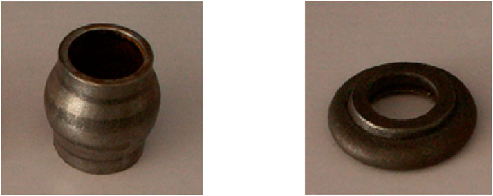
High-strength yielding bolts are typically equipped with spherical yielding tubes, as shown in Figure 2. The yielding tube possesses a designated yield working load. When the axial force on the bolt reaches this value, yielding deformation initiates to prevent premature bolt detachment. It is necessary to strike a balance because excessive yield deformation can compromise the overall stability of the supporting structure and reduce available space. Therefore, to accommodate varying surrounding rock deformations and pressures in deep soft rock roadways, the yield range of the yielding tube should be controlled. The fundamental mechanical parameters of the yielding tube encompass the yield point, maximum yield distance, and yield stability coefficient.
(1) Yield point: The yield point of the yielding tube is reached when it transitions from elastic deformation to plastic deformation, and the load it carries at this point is termed the yield point. The load at this stage is also known as the initial yield load P0.
(2) Maximum yield distance: This refers to the distance by which the yielding tube extends from the onset of yield to the beginning of axial load. Dmax can be given by Equation 1.
Where, DE is the axial deformation of the bolt when the yielding tube loses its yield functionality; DB is the axial deformation of the bolt when the yielding tube first begins to yield.
(3) Yield stability coefficient: To assess the stability performance of the yielding tube during its operational phase, the yield stability coefficient is defined by Equation 2.
Where, ψ is the yield stability coefficient, t/mm, ψ ≤ 0.2; Pt is the final yield load, that is, the load when the yield deformation is complete and the stress of the bolt rod begins to increase, t; Dp is the maximum yield deformation, signifying the deformation of the yielding tube from the onset of yield to the end of yield.
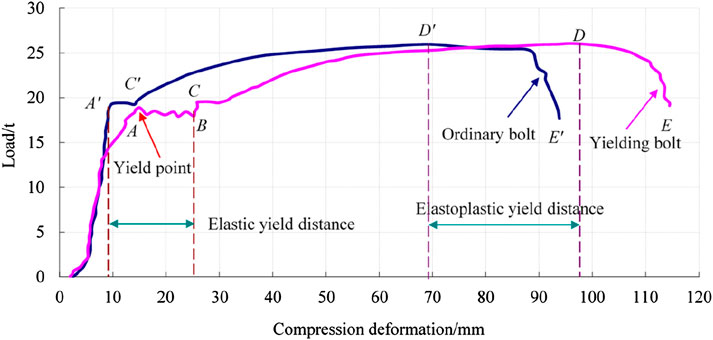
The uniaxial compression test curve of the yielding tube was obtained through lab analysis, as shown in Figure 3A. It can be seen from the figure that the compression deformation process of the yielding tube can be roughly divided into three stages: the elastic deformation stage (OA), the plastic yield stage (AB), and the infinite strengthening stage (BC). These three stages reflect the deformation characteristics of the yielding tube under varying external loads. To provide a clearer description of its mechanical properties, it can be simplified into the mechanical model as shown in Figure 3B.
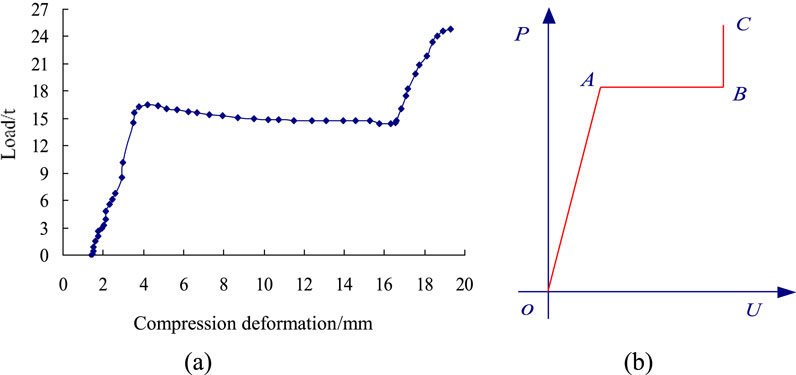
Figure 3. Test curve and mechanical properties of spherical yielding tube under uniaxial compression: (A) uniaxial compression test curve; (B) mechanical characteristics curve.
2.2 Mechanical properties analysis of high-strength yielding bolt
Pulling test can be used to analyze and compare the mechanical differences between an ordinary bolt and a yielding bolt (Salcher and Bertuzzi, 2018), as shown in Figure 4. Upon comparing the experimental curves, the following observations can be made:
When the external load reaches 18.9 t, signifying the yield point, the yielding tube begins to deform and enters the operational state. The elastic yield distance of the yielding bolt measures 16.15 mm, with the bolt body still in the elastic deformation stage. Before reaching the yield point, the deformation of the yielding bolt amounts to 17.18 mm, which is 1.91 times that of the ordinary bolt in the elastic stage. This indicates that approximately 47.6% of the deformation is attributed to the yielding tube.
In the case of an ordinary bolt, when the axial load reaches 19.23 t, it has already reached its ultimate yield strength, resulting in approximately 9 mm of deformation. This situation poses a risk of bolt detachment and failure when dealing with highly deformable roadways. Conversely, for the yielding bolt, when it reaches the yield limit load of 19.23 t, the axial deformation of the bolt measures 25.86 mm, which is 2.87 times greater than that of an ordinary bolt. This indicates that the yielding bolt possesses a robust deformation capacity, effectively preventing bolt failure.
The plastic limit load for both types of bolts is approximately 26.05 t. For the ordinary bolt, this corresponds to an axial deformation of about 69.33 mm. In contrast, the yielding bolt exhibits an axial deformation of approximately 96.02 mm, with an elastoplastic yield distance is 26.69 mm. The results indicate that the yielding bolt retains its yield performance even in the plastic stage. Compared to the elastic yield function, the plastic yield function not only allows for a greater degree of deformation in the surrounding rock but also diminishes the impact of dynamic loads on the roadway’s surrounding rock. This proves advantageous for the support design and construction of roadways.
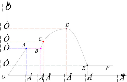
Based on the structural characteristics of the yielding bolt and considering the drawing test curve and anchoring state during roadway support (for instance, from the end bolt to the full-length bolt after grouting), the strength strain curve of the high-strength yielding bolt is divided into 6 stages, as shown in Figure 5.
(1) Stage OA: During this stage, the yielding bolt undergoes elastic deformation due to applied force, which comprises the elastic deformation of the bolt body and the elastic deformation of the yielding tube. Point A represents the yield point, and the stress-strain relationship during this stage adheres to Hooke’s body model by Equation 3.
Where, E1 is the elastic modulus of the bolt body; E2 is the elastic modulus of the yielding tube; ε1 is the strain of the yielding tube before yield.
(2) Stage AB: In this stage, the yielding tube of the yielding bolt begins to take effect, causing the surrounding rock in the roadway to exhibit constant resistance deformation as it interacts with the yielding tube. This deformation continues until the yielding tube flattens, and the length of the bolt rod extends. During this stage, the primary deformation in the bolt body is yield sliding deformation, similar to that of a Saint Venant body. The stress-strain relationship can be expressed by Equation 4.
Where, ε2 is the strain at the end of the yield deformation of the yielding tube.
(3) Stage BC: Since the yield load (denoted as point C yield stress σs) of the bolt exceeds the yield point load, and the stress in the bolt body decreases during the yield process while remaining within the elastic deformation range of the bolt body, this stage is represented by Equation 5.
Where, ε3 is the strain of the bolt body when it reaches the yield limit.
(4) Stage CD: At this stage, the load on the bolt rod exceeds the yield limit stress, and its resistance to deformation is strengthened due to changes in the internal structure of the rod body. Deformation during this stage consists of both elastic and plastic deformation. The deformation curve is concave as stress increases, and the stress-strain relationship is notably nonlinear, which can be described using a generalized Kell style model by Equation 6.
Where, η is the viscosity of the bolt body and ε4 is the strain when the bolt body reaches the strength limit.
(5) Stage DE: During this stage, the bolt body exhibits signs of damage and softening characteristics. There is a sudden and significant reduction in its transverse size within a specific local range, known as the necking phenomenon. As the stress on the bolt exceeds its tensile strength (point D strength limit σb), the bolting force of the bolt declines rapidly. If allowed to progress, bolting will ultimately fail. The stress-strain relationship is roughly expressed by Equation 7.
Where, Er is the damage elastic modulus of the bolt body; ε5 is the strain at the end of the damage softening of the bolt body.
(6) Stage EF: Due to the coordinated development of the deformation relationship between the bolt support system and surrounding rock, if the bolt is not pulled out from the surrounding rock or is reinforced through grouting before failing, the bolting force of the bolt does not dissipate entirely and retains a certain ability to resist the deformation of the surrounding rock (Aghchai et al., 2020). This phase is defined as the residual strength stage, in which the bolt maintains a constant residual strength is expressed by Equation 8.
Where,
2.3 Yielding bolt support control mechanism
In the context of deep soft rock roadways, enhancing the strength of the bolt can enhanced the mechanical parameters of the surrounding rock. As the bolt’s strength increases, its elongation decreases, leading to reduced deformation energy consumption. However, even with higher-strength bolts, a significant portion of the deformation energy within the surrounding rock of the roadway still needs to be released. The presence of the yielding tube effectively solves this problem. The supporting control mechanism of a high-strength yielding bolt encompasses the following aspects (Lian et al., 2008; Zuo et al., 2023).
2.3.1 Yield adjustment of surrounding rock stress distribution
After the excavation of a deep roadway, the original stress equilibrium within the surrounding rock is disrupted. As the surrounding rock stress readjusts and redistributes, it leads to varying degrees of damage in the radial direction of the roadway, from the surface inward. This can be categorized into four zones, as shown in Figure 6A. Figure 6B shows the impact of yielding bolt installation on the stress distribution of the surrounding rock, which includes (Lian et al., 2008): U1 is the convergence and deformation of the surrounding rock before the yielding bolt undergoes yield; U2 is the convergence and deformation of roadway’s surrounding rock after the yielding bolt has yielded.
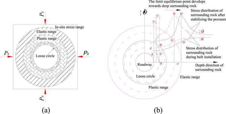
Figure 6. Damaged regions of the surrounding rock of circular roadway and stress distribution after supported by yielding bolts. (A) P0-Original rock stress. (B) σr-Radial stress; σθ-Tangential stress; U1-Deformation of surrounding rock before anchor yield; U2-Deformation of surrounding rock after anchor yield; H-Allow maximum tangential stress before pressing; H’-Maximum tangential stress after rolling; G-Maximum radial stress before pressure; G’Maximum radial stress after yielding; Δx-Moving distance of surrounding rock.
With the increase of the U1, the bolting force of the yielding bolt continues to rise. However, when the yield point is reached, the yielding tube of the yielding bolt begins to provide constant resistance yielding, and the U2 is generated. During this process, the axial stress within the roadway’s surrounding rock gradually decreases until it reaches the equilibrium point A in conjunction with the anchoring force of the yielding bolt. Simultaneously, the maximum tangential stress within the roadways surrounding rock also shifts to greater depths, transitioning from point H to point H’. At this time, the rock mass at point H′ is in a state of limited equilibrium, and the plastic area of the surrounding the rock no longer expands, approaching stability. It is evident that when utilizing yielding bolts for support, the surrounding rock can actively undergo yielding while effectively relocating the limit balance point deeper within the surrounding rock. This, in turn, helps control the expansion of the loose circle and the plastic zone within the surrounding rock more efficiently, ensuring the overall stability of the surrounding rock.
2.3.2 Yield to prevent the bolt from breaking
In deep soft rock roadways, the adoption of high-strength pre-stressed yielding bolt support effectively eliminates the issue of bolt breakage. This occurs because, under low roadway surrounding rock pressure conditions, the yielding bolt’s support and performance are equivalent to that of a standard pre-stressed bolt. However, in scenarios where the roadway surrounding rock experiences high pressure, the load exceeds the yielding tube’s yield point, initiating yielding. This process absorbs the deformation energy from the roadway’s surrounding rock, allowing the bolt rod to maintain a constant resistance to elongation. It postpones the moment when the bolt rod yields, preventing a rapid increase in surrounding rock pressure that could lead to bolt rod breakage. Consequently, this ensures the stability of the entire supporting system.
2.3.3 Relationship between bolting force and surrounding rock deformation
The shear dilatancy deformation following the peak in surrounding rock leads to the anchoring force of the yielding bolt, encompassing both radial stress and tangential stresses. Before yielding, the anchoring force increases in tandem with the growth of dilatancy deformation. During the yielding process, dilatancy deformation continues to increase while the bolting force remains constant, ensuring the surrounding rock maintains a stable equilibrium even under high-stress conditions.
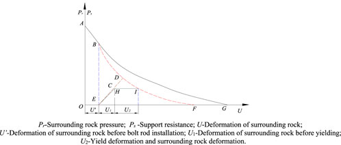
The relationship curves between surrounding rock deformation and bolting force in Figure 7 are as follows: ABG is no support; ABDF and ECD for the ordinary bolt anchoring force effect; ABDF and EHI acts on the anchoring force of yielding bolt. The application of yielding bolts can alleviate surrounding rock deformation. When compared to ordinary bolts, the stress within the surrounding rock and the bolting force can achieve a balanced state even with lower applied force.
Before the introduction of yielding bolt support, the bolting force of the bolt serves to support and strengthen the surrounding rock. As the deformation of the surrounding rock increases, most of the deformation energy of the surrounding rock is primarily transformed into the elastic strain energy (EC or EH) of the bolt rod. When yielding initiates, the deformation energy of the surrounding rock is absorbed by the yielding tube, and the bolting force remains constant (CD or HD).
2.3.4 Relation between yield distance and support strength
The yielding bolt permits the roadway’s surrounding rock to undergo a certain level of deformation by compressing the yielding tube. Excessive deformation, however, can reduce the overall stability of the supporting system. Therefore, the reasonable determination of the yield distance is crucial to ensuring proper coordination between the supporting body and the surrounding rock of the roadway. The yield distance is closely related to the strength of the bolt support. For a circular or curved roadway, when bolting is used for reinforcement, it can form a composite arch or balanced bolt arch. In such cases, the support strength can be calculated using the lamay formula (Lian et al., 2008). It can be expressed as the Equations 9, 10.
Where, p is the strength of bolt solid support; σ is the strength of bolt solid; b is the composite arch thickness; R is the net radius of roadway; L is the effective length of the bolt; α is the control angle of the bolt in the rock mass, generally 45° can be taken; d is the row distance between the bolts.
Under the condition that other parameters remain constant when yielding bolts are used for surrounding rock support, the increase in support strength Δp is due to the yield distance ΔL, Δp is represented by Equation 11.
From the analysis above, it becomes evident that during the yielding process of the yielding bolt, if the strength of the bolt remains consistent, meaning the original rock mass strength remains unchanged, the yielding deformation of the yielding bolt will enhance the thickness of the composite arch. This, in turn, improves the supporting strength of the composite arch.
3 Control mechanism of grouting reinforcement
Grouting reinforcement involves the injection of flowing grout into cracks or pores within the surrounding rock. This grout subsequently solidifies, enhancing the physical and mechanical properties of the surrounding rock and serving purposes like cementation and water blocking. Beginning with an understanding of the failure mechanisms and mechanics principles of rock masses, the control mechanism of grouting reinforcement is outlined as follows (Zhang et al., 2015; Pan and Wang, 2024):
3.1 Network framework action
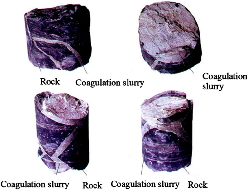
During the process of grouting reinforcement, grout can be extruded or infiltrated intersecting cracks with the rock mass due to grouting pressure and the capillary suction effect of micro-cracks. Once the grout solidifies, it fills the crack in the surrounding rock, creating a new network skeleton structure as shown in Figure 8. When external loads exceed the strength of the surrounding rock, this newly formed network skeleton structure serves as a framework, limiting the further expansion of the failure zone within the surrounding rock. Consequently, the rock mass maintains its structural integrity.
3.2 The function of sealing water source
Groundwater can have a softening and dissolving effect on the surrounding rock of a roadway, potentially degrading its properties. Numerous studies indicate that as water content increases, rock strength decreases significantly (Lu et al., 2017; Li et al., 2019; Luo et al., 2022; Ji et al., 2024; Chen et al., 2025). This effect is particularly pronounced in soft rock surrounding rock that contains clay, where expansion deformation can be substantial. Grouting of the surrounding rock can act to block flow channels, thereby isolating the potential weakening impact of groundwater, aquifer water, fissure water, and fault water on the surrounding rock of the roadway.
3.3 Bonding reinforcement
According to Mohr’s strength theory, the strength of a rock mass is determined by two key factors: cohesion and the internal friction angle. Grouting serves the purpose of strengthening the rock mass within the loose circle. It enhances the cohesion and internal friction angle of the cracks between rock masses, bolstering the resistance to relative displacement between them. Ultimately, this process widens the gap between the Mohr circle and the strength envelope, leading to a more uniform distribution.
3.4 Filling and compaction action
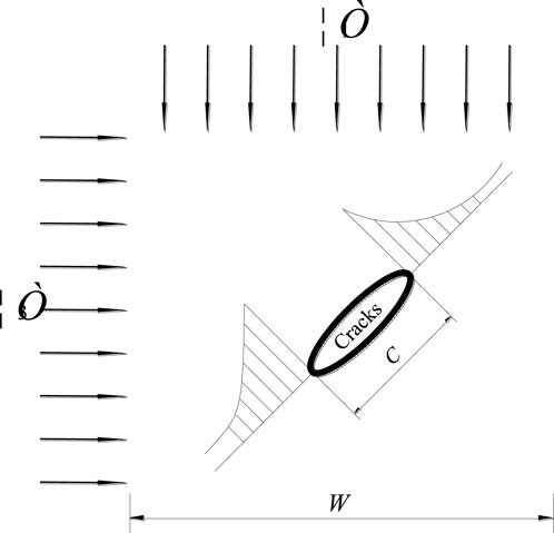
When cracks or other weak surfaces exist within the rock mass, these cracks can result in significant stress concentration at their ends under load, as shown in Figure 9. In cases where the rock mass contains substantial cracks, the introduction of grouting reinforcement materials to fill these cracks can lead to a change in the stress state of the rock mass surface within the cracks. Transitions from a two-way stress state to a three-way stress state, result in an improved stress distribution throughout the rock mass and a substantial reduction or elimination of stress concentration. In the case of small cracks within the rock mass, grout material serves to compress them while filling the larger cracks. This compaction effect leads to an increase in the elastic modulus of the surrounding rock and an enhancement of its strength.
3.5 Transform the bearing structure
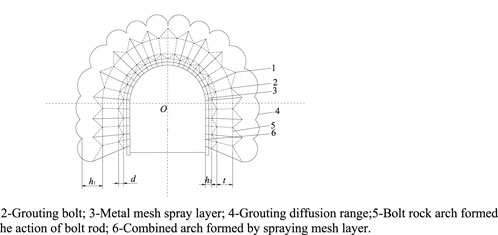
Grouting for the purpose of strengthening roadways in loose fractured rock masses has the capability to re-cement fragmented rock blocks into a unified structure, forming a reinforced arch. This significantly enhances the self-supporting capacity and overall stability of the supporting system. Moreover, grouting can also transform the end bolt rod into a full-length bolt, integrating it with the surrounding rock. In addition, grouting can facilitate the creation of a structural effect at critical points in the grouting reinforcement process, thus mitigating progressive failure in the surrounding rock of the roadway and improving its stability. Through the use of grouting to fill internal cracks within the surrounding rock and complementing it with shotcrete support, the support structure and surrounding rock form a multi-layer combined arch structure, as shown in Figure 10.
4 Yield-bolt-grouting coupling control technology for soft surrounding rock of deep water-enriched roadway
The soft surrounding rock of deep water-enriched roadway has the characteristics of fast rheological speed, large deformation amount, and long deformation time. If effective support measures are not taken in a timely manner, the surrounding rock of the roadway will quickly deform and lose stability in the early excavation stage. Beginning with the aim of reducing the weakening effect of water, improving the bearing capacity and strength of the surrounding rock, this paper introduces the “yield-bolt-grouting” coupling control technology system. The technical route is shown in Figure 11.
(1) High-strength support. Implementing a high-strength active support system effectively improves the peak strength and residual strength of the roadway’s surrounding rock. This, in turn, helps control the expansion and development of cracks.
(2) Moderate yield. The deformation in the deep roadway’s surrounding rock includes a portion of uncontrolled deformation. To address this, the support system should possess the capability for controlling yielding. Utilizing high-strength bolts with moderate deformation in a flexible support structure enables them to fulfill a high-strength yield role.
(3) Cut off the water source. Besides weakening the rock mass’s strength, water can also have a corrosive impact on supporting structures and surface protection structures. Hence, it is necessary to adopt controlled drainage technology to effectively channel water away from the surrounding rock of the roadway. This helps prevent water seepage into the roadway, safeguarding its long-term stability.
(4) Grouting reinforcement. Following the excavation of the deep roadway, the roadway’s surface is initially sprayed with shotcrete to prevent weathering from affecting the deep surrounding rock. In addition, grouting can enhance the cohesion and the internal friction angle of the surrounding rock, improve its strength and stability, seal cracks, block water ingress, and establish a stable foundation (Kim and Moon, 2020). In order to perfectly combine grouting reinforcement with moderate grouting, high-strength yielding grouting anchor rod (Figure 12) and high-strength yielding grouting anchor cable (Figure 13) have been designed and developed (Sun et al., 2018).
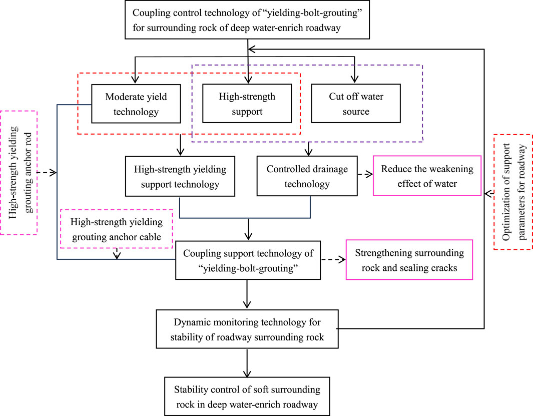
Figure 11. Technical route of “yield-bolt-grouting” coupling control for soft surrounding rocks in deep water-enriched roadways.
5 Engineering practice
5.1 Engineering background
The return air roadway of a certain mine in the Huaibei Mining Group is located at the level I of the north wing mining area, with a burial depth of about 700 m. The roadway is excavated along the N31°E bedding direction in a semi circular arch shape with a width of 5046 mm, a height of 4403 mm, and a length of 1285 m. The surrounding rock of the roof and floor is mainly composed of mudstone, and sandstone and siltstone are scattered. The main water sources for filling in roadway excavation are roof sandstone fissure water and fault water. The water abundance of the sandstone fissure aquifer on the roof is uneven, mainly controlled by the degree of development of structural fissures. In some areas, due to the influence of structures on the development of fissures, the water abundance is enriched. The normal water inflow of sandstone fissure aquifer is 3–5 m3/h, and it mostly enters the roadway in the form of seepage, dripping, and local water inrush, as shown in Figure 14. Due to the influence of water, the degree of mud formation in the surrounding rock of the roadway is severe, and the stability of the weakened roof is significantly reduced. The roadway was initially supported by anchor mesh cables with U-shaped steel frames, and the excavation face was characterized by surrounding pressure, resulting in a very large deformation of the roadway. In addition, due to long-term water seepage, the rock mass at the side is loose, leading to overall instability of the roadway.
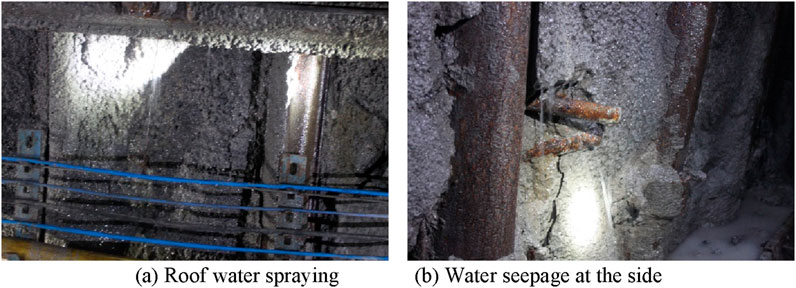
Figure 14. Water inrush forms in local position of the return air roadway. (A) Roof water spraying (B) Water seepage at the side.
5.2 Instability characteristics of roadway surrounding rock
Under the combined action of water weakening and high geostress, the development of cracks and significant fragmentation in the surrounding rock of the north wing return air roadway have made it difficult to manage the roadway. The deformation and instability of the roadway are significant, seriously affecting the normal and safe production of the mine. Its instability characteristics include the following aspects:
(1) The surrounding rock of the roadway weakens significantly after encountering water
After the excavation of the roadway, due to the relatively developed fractures in the surrounding rock, the intrusion of sandstone fissure water into the roadway resulted in severe weakening of the surrounding rock. The force foundation relied on by the anchor rod and anchor cable support has undergone deformation and looseness, which can easily lead to peeling of surrounding rock and failure of anchor rod (cable), as shown in Figure 15.
(2) Serious large deformation occurs in the surrounding rock of the roadway
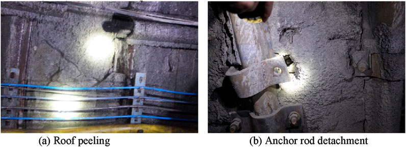
Figure 15. Damage characteristics of the return air roadway after water weakening. (A) Roof peeling (B) Anchor rod detachment.
The surrounding rock of the roadway is mainly composed of mudstone, which undergoes weakening, deliquescence, and expansion after encountering water intrusion. The combined effect of high geostress (measured vertical geostress is about 14.75 MPa) and weakened expansion has led to significant large deformation and failure in the roadway, resulting in significant roof subsidence, two sides moving closer, and floor plate bulging. There are also phenomena such as mortar cracking, tearing at the overlap of steel mesh, and twisting of the U-shaped steel support legs, as shown in Figure 16, which has had a serious impact on on-site production.
(3) The strength and integrity of the support material are damaged after encountering water
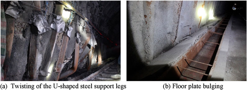
Figure 16. Large deformation instability phenomenon in the return air roadway. (A) Twisting of the U-shaped steel support legs (B) Floor plate bulging.
After encountering water intrusion in the roadway, the supporting materials such as U-shaped steel brackets, anchor rods (cables), and locks are severely corroded, as shown in Figures 15, 16, which seriously affects the strength of the supporting materials. When the roof sinks and the two sides are squeezed, these supporting materials are prone to fracture and failure, while their supporting accessories such as metal mesh are prone to deformation and instability, thereby causing damage to the integrity of the entire support structure, reducing the stiffness and strength of the support system. In addition, after encountering water, the adhesive strength of the resin roll decreases, resulting in a significant weakening of the adhesive strength between the anchor rod and the surrounding rock, further exacerbating the deformation of the surrounding rock.
5.3 Control scheme design of roadway surrounding rock
5.3.1 Surrounding rock support scheme
Based on the deformation and failure characteristics of the surrounding rock of the deep water-enriched roadway, combined with the previous theoretical analysis and laboratory test results, the surrounding rock control scheme with “yield-bolt-grouting” coupling support as the core should be focused on the northern wing return air roadway. After the high stress release and readjustment, that is, after the initial support structure is reasonably pressurized and before the intrusion of fissure water or fault water, measures such as internal grouting and surface spraying of the roadway surrounding rock are taken to timely block the fissure water conduit, improve the rock mechanical properties, and prevent the weathering or deliquescence of weak rock stratum around the roadway, thus achieving the maintenance goal of both internal and external treatment.
Firstly, the roof of the roadway, as well as the roadway’s sides, are supported using high-strength yielding rebar bolts in combination with M-shaped steel bands, rhomboid metal mesh for initial support, and high-strength yielding grouting anchor cables for reinforcement of key components. Then, the roadway floor is supported with high-strength yielding grouting anchor rods and channel steel. Lastly, the surrounding rock of the roadway was reinforced with delayed grouting to seal the cracks and improve anchoring strength. The support scheme and parameters for the north wing return air roadway are shown in Figure17.
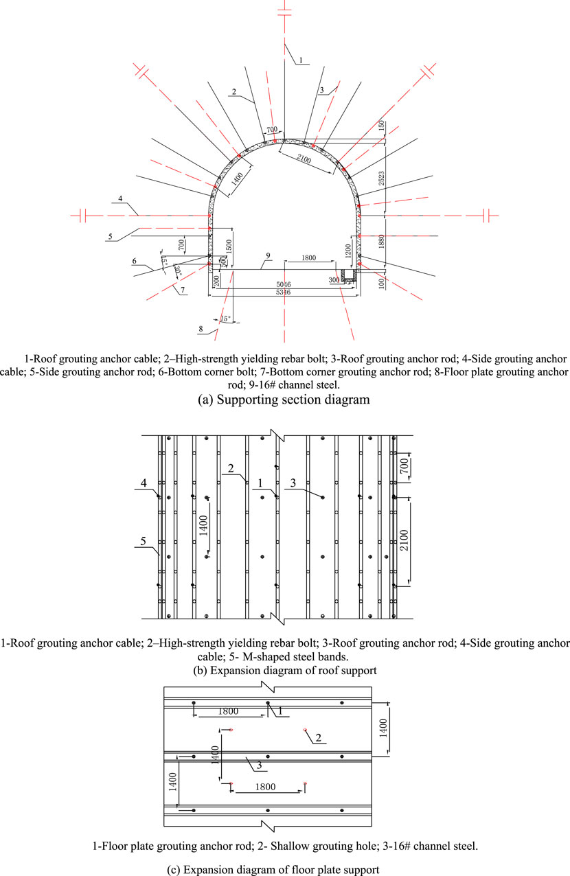
Figure 17. Supporting scheme for the main return air roadway. (A) Supporting section diagram, (B) Expansion diagram of roof support, (C) Expansion diagram of floor plate support.
5.3.2 Reasonably arrange drainage holes
Reasonable arrangement of drainage holes can reduce the weakening of water on the surrounding rock of the roadway. The main technical parameters include the diameter, length, yow line space and drilling inclination angle of the drainage holes, among them, the drainage hole diameter is ≥50.0 mm, the length of the drainage hole should be 2.0 m higher than the depth of the main fracture surface of the aquifer, the yow line space is generally taken as 20–50 m, and the drilling inclination angle is generally taken as 60°–75°. The length of drainage holes should be reasonably arranged along the direction, which can be given by the following equation:
Where L is the length of the drainage hole; L1 is the height of immediate roof; L2 is the length of the main fracture surface of the aquifer away from the immediate roof, m; L3 is the length of the drainage hole passing through the main fracture surface of the aquifer.
According to the specific hydrogeological conditions of the return air roadway, drainage holes with a diameter of 60 mm and an inclination angle of 65° are arranged in areas with abundant fissure or fault water. The length of the drainage hole passing through the main fracture surface of the aquifer is generally taken as 1.5–2.0 m. To ensure safety, we take the maximum value of 2 m, with L1 taking 2.87 m and L2 taking 4.31 m. According to Equation 12, the drilling length L is rounded to 10 m. At the same time, a water diversion tube is installed at the end of the drilling hole to concentrate the discharge of fissure water or faults, reducing the erosion and collapse of water on the surrounding rock of the roadway. After the completion of water diversion work, grouting should be used in a timely manner to seal the hole.
5.4 Observation of deformation of surrounding rock in deep soft rock roadway
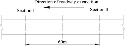
To better assess the coupling support effectiveness of “yield-bolt-grouting”, two monitoring sections were established in the main return air roadway of a mine in the Huaibei Mining area, separated by a distance of 60 m. These sections were used to monitor the grouting effect and surface displacements of the roadway, as shown in Figure 18.
Following grouting, the surface displacement observations of the roadway are shown in Figure 19. The data reveals that during the observation period, at Section Ⅰ's observation point, there was a roof subsidence of 89 mm, floor heave of 67 mm, top-to-bottom displacement of 156 mm, and lateral displacement of 102 mm. At Section II’s observation point, the roof subsidence measured 86 mm, floor heave was 64 mm, top-to-bottom displacement amounted to 150 mm, and lateral displacement reached 106 mm. Starting from the 36th day, the deformation rate of the surrounding rock in the roadway significantly decreased and exhibited signs of rapid convergence, signifying the effective stability provided by the Yield-bolt-grouting coupling support scheme.
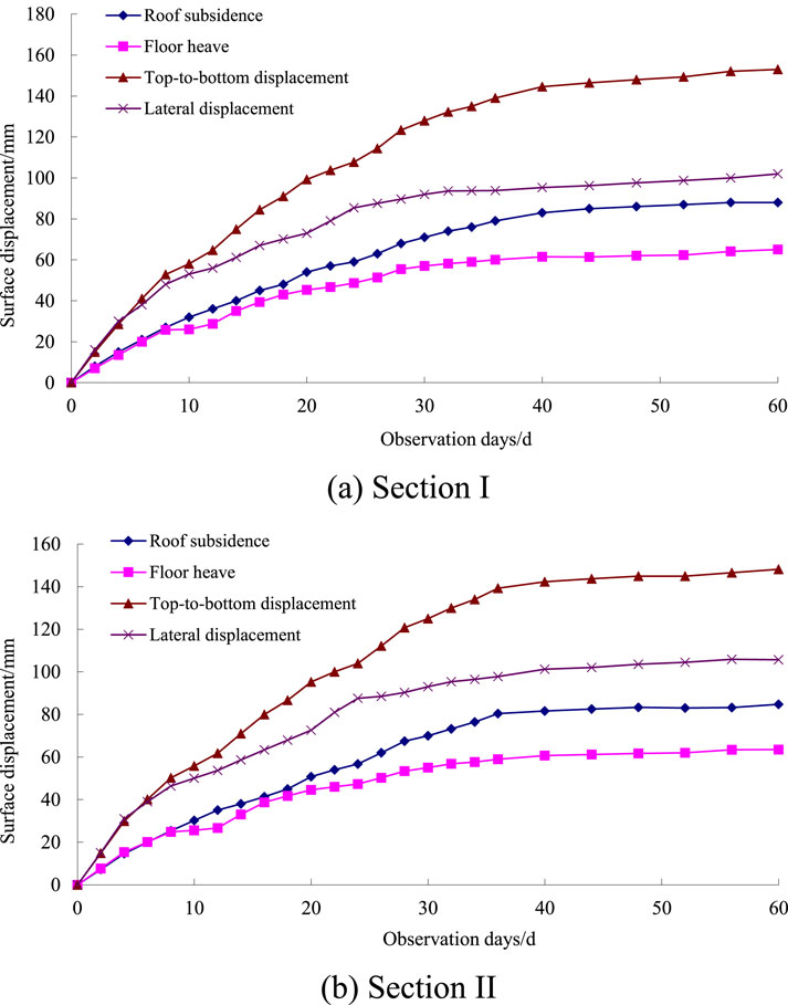
Figure 19. Surface displacement curve of the main return air roadway. (A) Section Ⅰ, (B) Section II.
6 Discussion
As shallow coal resources are increasingly depleted, coal mines in the eastern and some central and western mining areas of China are gradually shifting to deep mining at a rate of 8–12 m per year, with some mines already exceeding a mining depth of 1 km (Xie et al., 2022). Compared to shallow roadway engineering, deep roadway engineering is in a complex mechanical environment characterized by high geostress, strong permeable water pressure, and intense mining disturbances (Frenelus et al., 2022; Park and Michalowski, 2019). The deformation and failure of surrounding rock exhibit distinct large deformation features, with the failure mode transitioning from brittle to ductile (Shi et al., 2023; Shu et al., 2023). Under the coupled effects of high geostress and strong permeable water pressure, groundwater enters the coal-measure rock strata surrounding the roadway through dynamically developed fractures, weakening the bearing capacity of the surrounding rock, which in turn reduces the load-bearing performance of the support structure, leads to anchor failure, and induces significant deformation and failure of the surrounding rock. This poses a serious threat to the safe and efficient mining of deep coal seam (Shi et al., 2024).
As mentioned in the introduction, current methods for controlling large deformation of deep roadways mainly involve pressure yielding or anchoring and grouting techniques. However, single-method control techniques are more commonly used, and the mechanisms behind them are insufficiently explained. Moreover, there are few combined control techniques that integrate both methods (Sun et al., 2018). Pressure yielding in the support system mainly utilizes its own deformation capability to absorb and release part of the uncontrollable deformation energy of the surrounding rock. As the deformation of the surrounding rock continues to increase, if measures such as grouting are applied to reinforce the surrounding rock before the failure of the support system, it can not only enhance the overall cohesion and internal friction angle of the surrounding rock, increasing its overall strength, but also provide a solid anchoring base for bolts and cables, improving the anchoring force and ensuring that the prestress and working resistance of the anchors can effectively diffuse into the surrounding rock, thus improving the support effect (Wu et al., 2020; Lu et al., 2022).
Therefore, this paper comprehensively considers the combined control of deep water-rich roadway surrounding rock through pressure yielding and anchoring-grouting, and has achieved good control results in engineering applications. Firstly, through pressure yielding tubes compression tests and anchor rods pull-out tests, corresponding mechanical models were established to analyze the mechanical properties of the pressure yielding tube and high-strength yielding bolts. The mechanism of controlling surrounding rock stress distribution, preventing bolt failure, the relationship between bolting force and surrounding rock deformation, and the relationship between yielding distance and support strength were comprehensively revealed, enriching the theoretical understanding of yielding control. Secondly, the control mechanism of grouting reinforcement was fully revealed from aspects such as the skeleton role of the grouting network, water source sealing effect, bonding and reinforcement effect, filling and compacting effect, and transformation of the load-bearing structure. Finally, based on the control mechanisms of yielding and grouting reinforcement, high-strength yielding grouting anchor rods and high-strength yielding grouting anchor cables were developed and designed. A coupling control method of “yielding-bolt-grouting” centered on grouting was proposed, providing a new technical approach to solve the problem of controlling surrounding rock in deep water-enrich roadways.
As the depth of coal mining increases, the impact of high temperature and water on the stability of surrounding rock in roadways is becoming increasingly evident. The author will conduct research on the deep pressure anchor grouting support technology under the influence of these two factors in the future.
7 Conclusion
This paper studies the coupling control mechanism of “yielding-bolt-grouting” in deep soft rock roadway. Combined with experimental results, theoretical analysis, and on-site application, the following conclusions can be drawn:
(1) The mechanical characteristics and support control mechanism of high-strength yielding bolts were determined through lab analysis. The results indicate that, before reaching the yield point, the axial deformation of the yielding bolt measures 17.18 mm, which is 1.91 times that of an ordinary bolt in the elastic stage. When the yield limit load is reached, the axial deformation of the bolt increases to 25.86 mm, which is 2.87 times that of an ordinary bolt. Under the plastic limit load, the elastic-plastic yield distance extends to 26.69 mm, ultimately enhancing roadway stability through interaction with the surrounding rock.
(2) Commencing with an examination of the failure mechanisms and mechanical principles of rock masses, this paper complies with the control mechanisms for grouting reinforcement. These mechanisms encompass the creation of a network framework, sealing water sources, achieving filling compaction, and changing the bearing structure.
(3) A coupling control technology system involving “yield-bolt-grouting” was proposed and subsequently subjected to field tests. During the observation period, on the 36th day, the deformation rate of the surrounding roadway significantly decreased and approached convergence. This underscores the effectiveness of the “yield-bolt-grouting” coupling support scheme in ensuring the stability of the surrounding rock in deep soft rock roadways.
Data availability statement
The original contributions presented in the study are included in the article/supplementary material. Further inquiries can be directed to the corresponding author.
Author contributions
JZ: Writing–original draft, Writing–review and editing, Conceptualization, Data curation. QR: Writing–original draft, Formal Analysis. LW: Writing–review and editing, Investigation. YY: Writing–original draft, Methodology. JC: Writing–original draft, Project administration. WS: Writing–original draft, Software. CW: Writing–review and editing, Supervision. WL: Writing–review and editing, Visualization.
Funding
The author(s) declare that financial support was received for the research, authorship, and/or publication of this article. This work was funded by the National Natural Science Foundation of China under Grant Nos. 51904112, the Blue Engineering Talent Project of Jiangsu Province, the Scientific and Technological Guidance Project of Jiangsu Construction System Nos 2018ZD268 and 2017ZD246.
Conflict of interest
The authors declare that the research was conducted in the absence of any commercial or financial relationships that could be construed as a potential conflict of interest.
Generative AI statement
The author(s) declare that no Generative AI was used in the creation of this manuscript.
Publisher’s note
All claims expressed in this article are solely those of the authors and do not necessarily represent those of their affiliated organizations, or those of the publisher, the editors and the reviewers. Any product that may be evaluated in this article, or claim that may be made by its manufacturer, is not guaranteed or endorsed by the publisher.
References
Aghchai, M. H., Maarefvand, P., and Rad, H. S. (2020). Analytically determining bond shear strength of fully grouted rock bolt based on pullout test results. Period. Polytech. Civ. Eng. 64 (1), 212–222. doi:10.3311/ppci.15195
Cao, Y. X., Zhang, J. P., Yang, T., Chu, H. B., Zhang, X., and Zhang, T. (2023). Mechanism and application of prestressed yielding support for large-span roadway in multistress concentration areas. Processes 11 (6), 1600. doi:10.3390/PR11061600
Chen, C. J., Wei, J. P., Zhang, T. G., Zhang, H. D., and Liu, Y. (2025). Effect of abrasive volume fraction on energy utilization in suspension abrasive water jets based on VOF-DEM method. Powder Technol. 449, 120427. doi:10.1016/j.powtec.2024.120427
Chen, L. L., Wang, Z. L., Wang, W., and Zhang, J. X. (2023). Study on the deformation mechanisms of the surrounding rock and its supporting technology for large section whole coal cavern groups. Processes 11 (3), 891. doi:10.3390/PR11030891
Cheng, J. Y., Wei, Z. J., Bai, J. C., Yu, Z. Z., Xing, K. K., Li, Q. M., et al. (2022). Study on floor heave control technology of deep tectonic stress water-rich soft rock roadway based on blasting pressure relief. Coal Sci. Technol. 50 (07), 117–126. doi:10.13199/j.cnki.cst.2020-1232
Du, M. Q., Fan, G. W., Zhang, D. S., Jiang, S. Y., Wu, X. J., and Song, G. (2021). Research on surrounding rock control technology of roadway with weakly cemented coal-gangue interbedded roof under water-rich conditions. Coal Technol. 40 (11), 7–11. doi:10.13301/j.cnki.ct.2021.11.002
Fan, H., Niu, X. A., and Li, S. B. (2023). Failure mechanism and control technology for coal roadway in water-rich Area. Sustainability 15 (1), 410. doi:10.3390/su15010410
Frenelus, W., Peng, H., and Zhang, J. (2022). An insight from rock bolts and potential factors influencing their durability and the long-term stability of deep rock tunnels. Sustainability 14 (17), 10943. doi:10.3390/su141710943
Ji, S. T., Lai, X. P., Cui, F., Liu, Y., Pan, R. K., and Karlovšek, J. (2024). The failure of edge-cracked hard roof in underground mining: an analytical study. Int. J. Rock Mech. Min. Sci. 183, 105934. doi:10.1016/j.ijrmms.2024.105934
Kabwe, E. (2020). Numerical analysis of a rock bolt load indicator washer neglecting the stress relaxation effect. Min. Metallurgy & Explor. 37 (2), 691–700. doi:10.1007/s42461-020-00187-9
Khaleghparast, S., Aziz, N., Remennikov, A., and Anzanpour, S. (2023). An experimental study on shear behaviour of fully grouted rock bolt under static and dynamic loading conditions. Tunn. Undergr. Space Technol. 132, 104915. doi:10.1016/j.tust.2022.104915
Kim, Y., and Moon, J. S. (2020). Change of groundwater inflow by cutoff grouting thickness and permeability coefficient. Geomechanics Eng. 21 (2), 165–170. doi:10.12989/gae.2020.21.2.165
Komurlu, E., Demir, A. D., and Celik, A. G. (2020). Investigation of load bearing capacities of grouted rock bolts with new auxetic head designs. Period. Polytech. Civ. Eng. 64 (3), 782–791. doi:10.3311/ppci.16366
Li, B. Y., Liu, J., Bian, K., Ai, F., Hu, X. J., Chen, M., et al. (2019). Experimental study on the mechanical properties weakening mechanism of siltstone with different water content. Arabian J. Geosciences 12 (21), 656. doi:10.1007/s12517-019-4852-8
Lian, C. J., Xu, W. Y., and Wang, Z. H. (2008). Analysis of deformation characteristic and supporting mechanism of a new-typed yielding anchor bolt. J. Disaster Prev. Reduct. Eng. 2, 242–247. doi:10.13409/j.cnki.jdpme.2008.02.005
Lin, W. G., Cheng, J. L., Li, D. L., and Dang, H. B. (2022). Deformation characteristics and control technology of roadway in water-rich soft rock. Geofluids 2022, 1–8. doi:10.1155/2022/2234334
Liu, T. X., Yan, S., and Han, L. (2020). Combined control technology of destressing and yielding support in high-stress and large deformation roadway. Coal Sci. Technol. 48 (S2), 269–276.
Lu, H. F., Yin, J. L., Liu, Q. S., Cao, A. D., Wei, A. C., and Zhang, K. (2022). A self-dissolved grouting reinforcement method for water-rich soft rock roadway. Bull. Eng. Geol. Environ. 81 (7), 256. doi:10.1007/s10064-022-02744-6
Lu, Y. L., Wang, L. G., Sun, X. K., and Wang, J. (2017). Experimental study of the influence of water and temperature on the mechanical behavior of mudstone and sandstone. Bull. Eng. Geol. Environ. 76 (2), 645–660. doi:10.1007/s10064-016-0851-0
Luo, D. N., Xie, Y. Q., Lu, S. H., and Su, G. S. (2022). Experimental study on the effects of water saturation on the microseismic and acoustic emission characteristics of sandstone in different stress states. Rock Mech. Rock Eng. 55 (11), 6583–6603. doi:10.1007/s00603-022-03001-8
Lv, B., Zhao, X. Z., Zhang, T. S., Han, M., and Cao, C. (2023). Design of yielding device and optimization of support scheme of anchoring system in large deformation roadway. J. Min. Strata Control Eng. 5 (04), 25–34. doi:10.13532/j.jmsce.cn10-1638/td.2023.04.001
Oppong, F., Yao, N., Zhang, W. H., Liu, Y. D., and Kolawole, O. (2023). Tentative application of expansive cementitious materials in grouting–A systematic review. Case Stud. Constr. Mater. 18, e02113. doi:10.1016/j.cscm.2023.e02113
Pan, R., Cheng, H., Wang, L., Huang, H. X., Cai, Y., Xu, S., et al. (2020). Analysis of the bolt-grouting support in deep roadway and combined high-strength bolt-grouting control technology. J. Min. & Saf. Eng. 37 (03), 461–472. doi:10.13545/j.cnki.jmse.2020.03.004
Pan, R., and Wang, L. (2024). Experimental study on the bearing behavior of bolted and grouted broken surrounding rock of deep roadways in a Coal Mine. KSCE J. Civ. Eng. 28 (9), 4032–4040. doi:10.1007/S12205-024-0018-7
Park, D., and Michalowski, R. L. (2019). Roof stability in deep rock tunnels. Int. J. Rock Mech. Min. Sci. 124, 104139. doi:10.1016/j.ijrmms.2019.104139
Pinazzi, P. C., Spearing, A. J. S. S., Jessu, K. V., Singh, P., and Hawker, R. (2020). Mechanical performance of rock bolts under combined load conditions. Int. J. Min. Sci. Technol. 30 (2), 167–177. doi:10.1016/j.ijmst.2020.01.004
Salcher, M., and Bertuzzi, R. (2018). Results of pull tests of rock bolts and cable bolts in Sydney sandstone and shale. Tunn. Undergr. Space Technol. 74, 60–70. doi:10.1016/j.tust.2018.01.004
Shi, H., Chen, W. L., Zhang, H. Q., Song, L., Li, M., Wang, M. J., et al. (2023). Dynamic strength characteristics of fractured rock mass. Eng. Fract. Mech. 292, 109678. doi:10.1016/j.engfracmech.2023.109678
Shi, H., Zhang, H. Q., Chen, W. L., Song, L., and Li, M. (2024). Pull-out debonding characteristics of rockbolt with prefabricated cracks in rock: a numerical study based on particle flow code. Comput. Part. Mech. 11 (1), 29–53. doi:10.1007/s40571-023-00607-9
Shu, L. Y., Yuan, L., Li, Q. X., Xue, W. T., Zhu, N. N., and Liu, Z. S. (2023). Response characteristics of gas pressure under simultaneous static and dynamic load: implication for coal and gas outburst mechanism. Int. J. Min. Sci. Technol. 33 (2), 155–171. doi:10.1016/j.ijmst.2022.11.005
Singh, P., and Spearing, A. J. S. (2021). An improved analytical model for the elastic and plastic strain-hardening shear behaviour of fully grouted rockbolts. Rock Mech. Rock Eng. 54 (8), 3909–3925. doi:10.1007/s00603-021-02439-6
Sun, X. K., Wang, L. G., Lu, Y. L., Jiang, B. Y., Li, Z. L., and Zhang, J. H. (2018). A yielding bolt-grouting support design for a soft-rock roadway under high stress: a case study of the Yuandian No. 2 coal mine in China. South. Afr. Inst. Min. Metallurgy 118 (1), 71–82. doi:10.17159/2411-9717/2018/v118n1a9
Tahmasebinia, F., Zhang, C., Canbulat, I., Vardar, O., and Savdam, S. (2018). Numerical and analytical simulation of the structural behaviour of fully grouted cable bolts under impulsive loading. Int. J. Min. Sci. Technol. 28 (5), 807–811. doi:10.1016/j.ijmst.2018.08.012
Wang, F. R., Wu, C. L., Yao, Q. L., Li, X. H., Chen, S. Y., Li, Y. H., et al. (2023). Instability mechanism and control method of surrounding rock of water-rich roadway roof. Minerals 12 (12), 1587. doi:10.3390/min12121587
Wang, H. T., Gao, G. L., Zhang, H. J., Li, J. J., Xie, X. L., and Zhao, W. L. (2024). Comparative study on control effect of deep roadway under full-length prestressed bolt-grouting support. J. Min. Sci. Technol. 9 (01), 53–65. doi:10.19606/j.cnki.jmst.2024.01.006
Wang, L., and Gao, Z. Y. (2021). Technology of multilevel roof control and yield supporting for large section mudstone roadway. Coal Technol. 40 (08), 60–63. doi:10.13301/j.cnki.ct.2021.08.016
Wu, J. Y., Jing, H. W., Gao, Y., Meng, Q. B., Yin, Q., and Du, Y. (2022). Effects of carbon nanotube dosage and aggregate size distribution on mechanical property and microstructure of cemented rockfill. Cem. Concr. Compos. 127, 104408. doi:10.1016/j.cemconcomp.2022.104408
Wu, J. Y., Jing, H. W., Yin, Q., Yu, L. Y., Meng, B., and Li, S. C. (2020). Strength prediction model considering material, ultrasonic and stress of cemented waste rock backfill for recycling gangue. J. Clean. Prod. 276, 123189. doi:10.1016/j.jclepro.2020.123189
Wu, J. Y., Wong, H. S., Zhang, H. Q., Yin, Q., Jing, H. W., and Ma, D. (2024). Improvement of cemented rockfill by premixing low-alkalinity activator and fly ash for recycling gangue and partially replacing cement. Cem. Concr. Compos. 145, 105345. doi:10.1016/j.cemconcomp.2023.105345
Xie, H. P., Lu, J., Li, C. B., Li, M. H., and Gao, M. Z. (2022). Experimental study on the mechanical and failure behaviors of deep rock subjected to true triaxial stress: a review. Int. J. Min. Sci. Technol. 32 (5), 915–950. doi:10.1016/j.ijmst.2022.05.006
Yang, T., Liu, J. Z., Luo, J. Q., Shen, Y. P., and Fu, P. (2023). Study on instability mechanism of soft rock roadway and pressure-relief bolt-grouting support technology. Sci. Rep. 13, 20667. doi:10.1038/S41598-023-47451-8
Yin, Q. H., Li, C. T., Li, T. C., Xue, K. L., and Gao, Q. Q. (2020). Study on stability control technology of water-rich soft rock roadway. Min. Saf. & Environ. Prot. 47 (01), 12–16. doi:10.19835/j.issn.1008-4495.2020.01.003
Zhai, W. L., He, F. L., Xu, X. H., Lv, K., Li, L., and Song, J. Y. (2022). Floor heave mechanism in water-rich soft rock roadways and a DS-IBA control approach. Geomatics Nat. Hazards & Risk 13 (1), 2107–2123. doi:10.1080/19475705.2022.2107439
Zhang, H., Li, Y. M., Wang, X. J., Yu, S. D., and Wang, Y. (2023). Study on stability control mechanism of deep soft rock roadway and active support technology of bolt-grouting flexible bolt. Minerals 13 (3), 409. doi:10.3390/MIN13030409
Zhang, J. G., Wang, Y. W., Qi, X. H., and Zhu, T. G. (2022b). Research on application of the Bolt-Truss coupling support technology in roadway with water-rich and soft rock. Front. Earth Sci. 10, 842672. doi:10.3389/feart.2022.842672
Zhang, J. H., Wang, L. G., Li, Q. H., and Zhu, S. S. (2015). Plastic zone analysis and support optimization of shallow roadway with weakly cemented soft strata. Int. J. Min. Sci. Technol. 25 (03), 395–400. doi:10.1016/j.ijmst.2015.03.011
Zhang, J. P., Liu, L. M., Liu, C. X., and Yang, L. (2022a). Mechanism and application of new prestressed yield bolt for controlling deep high-stress rock mass. Tunn. Undergr. Space Technol. 119, 104254. doi:10.1016/J.TUST.2021.104254
Zhao, C. X., Li, Y. M., Liu, G., and Meng, X. R. (2020). Mechanism analysis and control technology of surrounding rock failure in deep soft rock roadway. Eng. Fail. Anal. 115, 104611. doi:10.1016/j.engfailanal.2020.104611
Zou, Q. L., Hu, Y. L., and Zhou, X. L. (2024). Performance of metal circular tube under different loading amplitudes and dynamic resistance-yielding mechanism. Mater. Today Commun. 39, 108913. doi:10.1016/J.MTCOMM.2024.108913
Keywords: deep water-enriched roadway, roadway instability, yield-bolt-grouting coupling control, technology system, surrounding rock control
Citation: Zhang J, Rui Q, Wang L, Yang Y, Chen J, Shen W, Wang C and Liu W (2025) Research on the coupling control mechanism of yielding-bolt-grouting in deep water-enriched roadway and its engineering application. Front. Earth Sci. 12:1504755. doi: 10.3389/feart.2024.1504755
Received: 22 October 2024; Accepted: 24 December 2024;
Published: 22 January 2025.
Edited by:
Hao Shi, Anhui University of Science and Technology, ChinaReviewed by:
Hui Yu, Shandong University of Technology, ChinaZhang Jie, Xi’an University of Science and Technology, China
Copyright © 2025 Zhang, Rui, Wang, Yang, Chen, Shen, Wang and Liu. This is an open-access article distributed under the terms of the Creative Commons Attribution License (CC BY). The use, distribution or reproduction in other forums is permitted, provided the original author(s) and the copyright owner(s) are credited and that the original publication in this journal is cited, in accordance with accepted academic practice. No use, distribution or reproduction is permitted which does not comply with these terms.
*Correspondence: Jihua Zhang, emhhbmdqaDg0QGh5aXQuZWR1LmNu
 Jihua Zhang
 Qiao Rui
 Lianguo Wang2