- Jiangxi Hydraulic Safety Engineering Technology Research Center, Jiangxi Academy of Water Science and Engineering, Nanchang, China
The optimization of parameters for the construction of cut off walls using high spray method plays a crucial role in improving the permeability stability of hydraulic structures and ensuring the safe operation of water conservancy projects. However, limited by existing research methods, there is currently a lack of systematic research on the influence of construction parameters on the quality of cut off walls. This study fully considers the characteristics of high-speed slurry jet and soil dynamic failure in numerical simulation of the construction of cut off walls using high spray method. Based on the SPH method, a two-dimensional plane strain model of high-pressure jet grouting was established, and the influence of aperture, grouting pressure, and hole spacing on the failure process of soil and the quality of cut off walls is systematically analyzed. The results show that the soil mainly exhibits tensile failure under the continuous action of high-speed cement slurry during the construction of cut off walls using high spray method. Reducing the aperture and grouting pressure, as well as increasing the hole spacing, are not conducive to forming a continuous and dense impermeable wall. Compared to grouting pressure, the influence of aperture and spacing on the quality of cut off walls is more significant. When the aperture is 0.6 m, the grouting pressure is 32 MPa, and the hole spacing is 0.8 m, the quality of cut off walls is great. Finally, the simulation results of this paper were preliminarily verified by combining the construction of cut off walls using high spray method in the flood control project in Luotang Township, Jiangxi Province, China. The findings can provide reference for optimizing the construction parameters of cut off walls using high spray method.
1 Introduction
The optimization of parameters for the construction of cut off walls using high spray method plays a crucial role in improving the permeability stability of hydraulic structures and ensuring the safe operation of water conservancy projects (Brown and Bruggemann, 2002; Wu et al., 2015; Yu et al., 2015; Heidarzadeh et al., 2019; Wang et al., 2021; Cheng et al., 2022). The high-pressure jet grouting method, also known as the high spray method, is a construction technique that uses the impact load generated by high-speed slurry jet to destroy the grouted soil, causing the slurry to mix and solidify with soil particles, thereby forming an impermeable wall. Due to its wide applicability, high wall quality, good controllability, and convenient construction, it has been a main method for the construction of cut off walls (Dai et al., 2020; Li et al., 2023; Zhang et al., 2024). Optimizing the high-pressure jet grouting method and improving the construction quality of cut off walls is a hot topic in the anti-seepage treatment of hydraulic engineering.
Numerous scientific researchers and engineering technicians have conducted extensive research on the grouting materials of high-pressure jet grouting, formation mechanisms of cut off walls, and key technical parameters. For grouting materials, Yang (2010) explored the construction process using cement paste as the main grouting material. Wang et al. (2019) found that the seepage control effect and stability of cut off walls formed by using a new non-aqueous reactive polymer material was better than that of the concrete cut off walls. Wu et al. (2023) compared the seepage resistance of three types of grouting materials: the mixture of polymer and cement, the mixture of geopolymer and cement, and the mixture of terracotta, phosphogypsum and cement, and found that the solidified silty soil with high polymer and cement has the best impermeability performance. For the failure mechanism of soil caused by jet flow, Yang (2008) pointed out that high-pressure jet is the main driving force to diffuse the stratum and recombine the coarse particles in the stratum, which also indicates that grouting pressure directly affects the quality of cut off walls. Guo (2021) found that the soil body under the action of jet mainly exhibits splitting failure mainly through indoor model test, and also analyzed the influence of grouting pressure, but the grouting pressure was small. In terms of key technical parameters, Yang et al. (2021) determined parameters such as the spacing of grouting holes, grouting pressure, and lifting velocity based on experiments, providing a reference for the related engineering construction. Huang (2010) analyzed the influence of factors such as nozzle diameter size and quantity, lifting speed, slurry ratio and density, spacing of holes, and wall layout on the quality of cut off walls. In addition, Liu et al. (2022) proposed a large-diameter drilling spraying integrated high-pressure grouting technology through equipment modification and research and development, breaking through the limitations of traditional small-diameter drilling and forming high-quality cut off walls. This provides valuable experience for the application of high-pressure spraying grouting technology in other anti-seepage projects, and indirectly illustrates that drilling diameter can also significantly affect the construction quality of cut off walls. As can be seen from the above, current research on high-pressure jet grouting mainly focuses on model tests and field tests. Although it can provide some reference for related engineering construction, it also faces problems such as high testing costs, long cycles, and limited research content. More specifically, the construction parameters that affect the quality of cut off walls mainly include aperture, grouting pressure, and hole spacing, but currently limited by research methods, there is a lack of systematic research on these construction parameters. In recent years, the continuous emergence of numerical simulation methods has provided ideas for solving this problem. However, the high spray pressure during the construction of cut off walls, the flow characteristics of slurry jets, the impact failure characteristics of soil, and the particle characteristics of soil pose certain challenges for numerical simulation research. Therefore, to facilitate more systematic research, there is an urgent need to explore a numerical simulation method that can better simulate the slurry jet and its dynamic interaction with soil.
The present study fully considered the characteristics of numerical simulation of cut off walls using high spray method, and established a two-dimensional plane strain model of high-pressure jet grouting based on SPH method. The influence of hole diameter, grouting pressure, and hole spacing on soil failure process and quality of cut off walls was systematically analyzed. Combined with the construction test of cut off walls using high spray method in Luotang Township, Jiangxi Province, China, the simulation results of this article were preliminarily verified. The findings can provide reference for optimizing the construction parameters of cut off walls using high spray method.
2 Numerical model of high pressure jet grouting based on SPH method
In the construction of cut off walls using high spray method, the impact failure process of soil under the action of slurry jet is a typical dynamic process. LS-DYNA has significant advantages in simulating the characteristics of impact failure and has been widely used in multiple fields such as water jet (Zhou et al., 2022), rock blasting (Wei et al., 2009), and projectile penetration (Zhang et al., 2023). It supports multiple numerical methods and algorithms, including SPH method, which is suitable for numerical simulation of the construction of cut off walls using high spray method in this paper.
2.1 Introduction to SPH method
SPH algorithm is a computational method used to simulate fluid dynamics, which does not rely on traditional grid (lattice) methods to solve the motion equations of continuous medium, but expresses the spatial and temporal distribution of physical quantities through the interaction between particles and them (Monaghan, 2005). This makes the SPH algorithm particularly suitable for handling large deformations and free surface flow problems, meeting the numerical simulation requirements of this study. During the calculation process, track the motion of each particle from a perspective of Lagrange. The equations of particle motion are usually discretized based on physical laws such as Newton’s second law of motion and the principle of conservation of mass.
The SPH algorithm utilizes a weight function called a smoothing kernel to estimate the physical quantities of particles and their spatial derivatives. The kernel function determines the strength of the interaction between particles and typically has a finite support domain, with only neighboring particles having an impact on the current particle. Macro variables are obtained by calculating the integral interpolation of discrete points within the domain. The approximate function of the particle is given by Equation 1
where f(x) is a function of the spatial coordinate x, Ω is the support domain for x, x-x′ is the distance between particles, h is the smooth length of SPH particles, smooth length varies with time and space, as shown in Figure 1, W (x-x′) is the kernel function, defined by the auxiliary function θ(x-x′), shown in Equation 2:
where d is the spatial dimension.
In the SPH method, the particle approximation method is used to write continuous integral equations into discrete equations as shown in Equation 3:
where ρi is the density of particle i, mi is the mass of particle i.
The conservation equations of mass, momentum, and energy in the N-S equation based on the SPH method can be found in the literature (Gingold and Monaghan, 1977).
2.2 High pressure jet grouting model
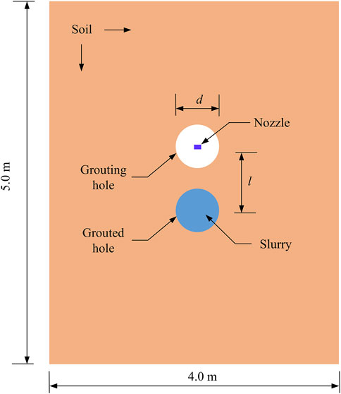
Referring to the construction process of cut off walls using high spray method, which has a better wall formation effect at present (Liu et al., 2022), a two-hole planar model was established, as shown in Figure 2. The overall dimensions of the model are 4 × 5 m2, and the boreholes are d in diameter and l in spacing. The direction of the grouting hole points in the direction of the preceding grouting hole, which is filled with grout that has not initially set. Fixed constraints were applied around the model. Both soil and slurry were simulated using SPH method.
There are two methods for generating SPH particles in LS-DYNA. One is to directly build the model in the post-processing software LS-PrePost. The other is to first create finite elements in software ANSYS and then import them into LS-PrePost to convert them into SPH particles. This study adopted the second method, which facilitates rapid modeling. In addition, to simulate high-pressure jet grouting, infinite slurry was used to achieve a continuous jet flow of slurry from the nozzle. The method for establishing the high-pressure jet grouting model is shown in Figure 3. To better simulate the impact failure phenomenon of soil body, the mesh in the finite element model was uniformly divided with a size of 1 cm, that is, SPH particle nodes were created with a spacing of 1 cm. Excluding the infinite slurry SPH particles, the total number of SPH particles in the model was 144,270. Three nozzles are simultaneously directed spraying, and the three nozzles are located very close to each other. A simplification is made in the 2D numerical simulation, where the slurry is equated from a point jet to a present jet.
2.3 Material model and parameters
The materials involved in this study mainly include soil and cement slurry. The constitutive model of soil was selected using the MAT-FHWA_SOIL_TITLE model provided by LS-DYNA. This model is suitable for simulating and analyzing the mechanical behavior of soil and has been widely used in numerical simulations of soil blasting seismic dynamic response, soil impact failure under water jet action, and soil cutting. This model modifies the standard Mohr-Coulomb yield surface to a smooth surface, improving the stability of calculations. The yield equation is expressed by Equation 4
where P is the pressure, φ is the internal friction angle, J2 is the second invariant of the deviatori tensor of stress, K(θ) is the function of tensor plane angle, c is the cohesive force, AHYP is a parameter for the similarity between the modified Mohr-Coulomb yield surface and the standard Mohr-Coulomb yield surface.
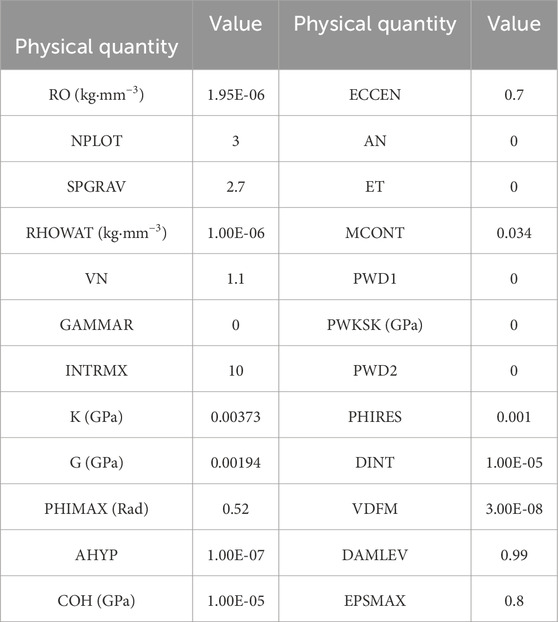
The above model simultaneously considers plastic hardening, plastic softening, strain rate effect, and pore water pressure effect. In addition, it also has the function of element or SPH particle failure. The main parameters controlling the soil mechanics behavior of the model include bulk modulus, shear modulus, soil density, moisture content, friction angle, and cohesion. Based on the parameters of soil in reference (Wu et al., 2024) and relevant explanations in the LS-DYNA keyword manual (Livermore Software Technology Corporation, 2003), the main parameters of soil are determined, as shown in Table 1.
The properties of cement slurry are very complex, and there is no mature material model available in LS-DYNA. This study uses the combination of the empty material model and the related equation of state to simulate cement slurry, which is commonly used to simulate fluid. Specifically, defining the density of 1.5 g/cm3 and dynamic viscosity of 2 Pa s using the keyword * MATNULL. Referring to the equation of state of the relevant fluid, simulating the properties of cement slurry. It should be noted that the dynamic viscosity of cement slurry will change over time, but considering the continuity of construction, the time interval between the construction of the two grouting hole is relatively short, and the influence of time on the viscosity of cement slurry was ignored in this study.
3 Factors affecting the quality of cut off walls using high spray method
3.1 Calculation conditions
Research shows that the main factors affecting the quality of cut off walls using high spray method are hole diameter, grouting pressure, and hole spacing. Conventionally, the diameter of grouting hole is less than 0.2 m, and the soil-breaking of high-speed slurry is very limited. In recent years, large-diameter grouting holes have gradually been applied due to their good soil-breaking effect. In this paper, grouting holes with diameters of 0.3 mm, 0.4, 0.5, and 0.6 m were selected to study the influence of diameter on grouting quality. The grouting pressure for high-pressure jet grouting is usually 20–40 MPa. The grouting pressures of 24, 28, 32, and 36 MPa were adopted. In numerical simulation, different grouting pressures were achieved by applying different initial velocities of particles, which were estimated based on the formula of small hole shooting flow. The hole spacing was set to 0.8, 1.0, 1.2, and 1.4 m for analysis. The calculation conditions are listed in Table 2.
3.2 Analysis of main influencing factors
Figure 4 shows the variation of the slurry zone between adjacent holes using high-pressure jet grouting method with a hole diameter of 0.6 m in the condition SCI-1. The red area in the figure represents the grout and the blue area represents the soil. In the figure, the red area represents the slurry while the blue area represents the soil. It is easy to find that the high-speed sprayed cement slurry did not initially cause failure to the soil after acting on the hole wall, but bounced off the hole wall and fell into the hole. Under the continuous action of high-speed cement slurry, radial cracks appeared around the wall of the grouting hole. This is because that the hole wall was subjected to impact load and tended to expand outwards, generating large tensile stress in the circumferential direction of the hole. At the same time, the hole already filled with slurry were subjected to compression, which also generated a certain amount of annular stress, resulting in some radial cracks. The slurry with a certain velocity entered the radial cracks, causing them to extend towards the front grouted hole. Finally, the grouting hole was connected to the front grouted hole to form a continuous cut off wall.
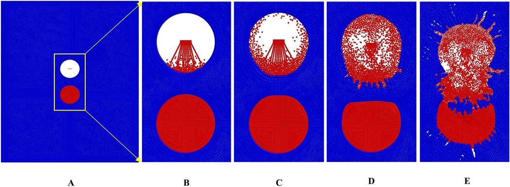
Figure 4. The grouting quality under the hole diameter of 0.6 m in the condition SCI-1. (A) Initial time. (B) 1/5 of the calculation time. (C) 2/5 of the calculation time. (D) 3/5 of the calculation time. (E) Final time.
Figure 5 presents the distribution characteristics of slurry between the two holes under different hole diameter conditions. As shown in Figure 5A, when the hole spacing and grouting pressure remained constant, the soil between the small diameter boreholes was thicker, and the guiding effect of the grouted holes on the cracks was not obvious. The soil around the grouting hole was significantly broken, but the soil between the grouting hole and the grouted hole was difficult to break, and the quality of the cut off wall was poor. In Figures 5A–C, the slurry between the two holes was not connected. As the hole diameter increased, the degree of soil failure between the two holes gradually increased, and the area filled with slurry also gradually increased. When the grouting pressure was 32 MPa and the hole spacing is 0.8 m, the slurry could only penetrate the two holes under the condition of a diameter of 0.6 m. At this point, the cut off wall was relatively continuous. The width of the wall is more likely to meet the design requirements. Based on the principle of equivalent area, the average thickness of the wall is 41 cm, as shown in Figure 5D.
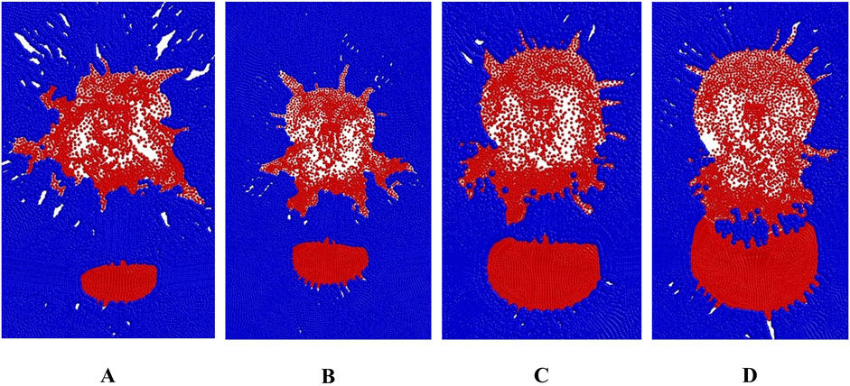
Figure 5. The filling area of slurry under different hole diameter conditions (A) d = 0.3 m (B) d = 0.4 m (C) d = 0.5 m (D) d = 0.6 m.
Figure 6 presents the distribution characteristics of slurry between the two holes under different grouting pressure conditions. Compared with the influence of the hole diameter on the grouting quality in Figure 5, the influence of the grouting pressure is not significant when it varies between 20–40 MPa. When the hole diameter was 0.6 m and the hole spacing was 0.8 m, the slurry in some areas between the two holes was not connected under the conditions of grouting pressure of 24 or 26 MPa. Correspondingly, the quality of the anti-seepage wall was poor. Under the conditions of grouting pressure of 32 or 36 MPa, although there was some soil wrapped in the slurry between the holes, the slurry and soil mixed together to form a dense and continuous wall. The greater the grouting pressure, the larger the width of the zone of slurry between the holes, and the better the wall quality.
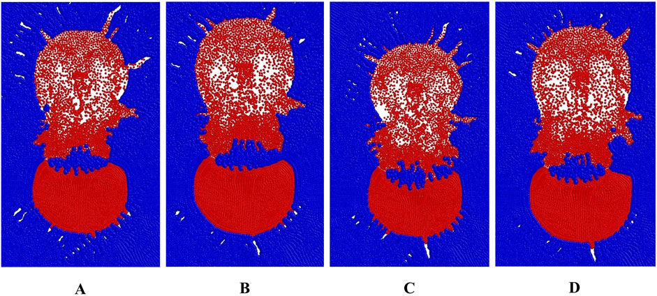
Figure 6. The filling area of slurry under different grouting pressure conditions. (A) p = 24 MPa. (B) p = 28 MPa. (C) p = 32 MPa. (D) p = 36 MPa.
Figure 7 shows the influence of hole spacing on the grouting quality between the two holes. When the grouting pressure was 32 MPa and the hole diameter was 0.6 m, the slurry area between the holes transitioned from a connected state to a non-connected state. When the hole spacing was 0.8 m, the slurry between the holes was connected, as shown in Figure 7A. When the hole spacing was 1.0, 1.2, and 1.4 m, the slurry was not connected, as shown in Figures 7B–D. As the hole spacing increased, the propagation direction of fractures in the soil under the high-speed slurry gradually deviated from the direction of the inter-hole centerline. Moreover, the larger the hole spacing, the greater the deflection angle, which leads to a gradual decrease in the grouting area between the holes and a deterioration in the quality of the cut off wall.
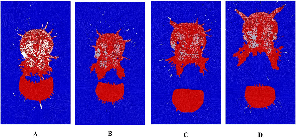
Figure 7. The filling area of slurry under different hole spacing conditions. (A) l = 0.8 m (B) l =1.0 m (C) l = 1.2 m (D) l = 1.4 m.
Comparing the distribution of slurry between holes and the average thickness of the wall under different conditions in Figures 5–7, it is found that the influence of hole diameter and spacing on the quality of cut off walls is more significant. Through the above analysis, it can be seen that, if the grouting technology with large diameter and high pressure is used for the construction of cut off walls, the quality of walls is better when the hole diameter is 0.6 m, the grouting pressure is 32 MPa, and the hole spacing is 0.8 m. Reducing the hole diameter and grouting pressure or increasing the hole spacing will lower the quality of cut off walls. Adjusting the hole spacing between holes is an effective method for controlling the quality of cut off walls. The present study provides a method for determining the optimal hole spacing given the hole diameter and grouting pressure, which can provide a reference for optimizing the construction parameters of cut off walls in water conservancy and hydropower projects.
4 Field experiment
Based on the above analysis, field experiments were conducted to test the construction quality of cut off walls using high spray method, relying on the flood control project in Luotang Township, Jiangxi Province, China. The project is located in the lower reaches of the Suichuan River, a tributary of the Ganjiang River, starting from Songyang Village and ending at Zhaitou Village. It is situated on the left bank of the Suichuan River and has a total length of 8.0 km for river regulation. The foundation of the Songyang embankment in the project location has serious leakage and poor flood resistance, which seriously affects the production and life of the local people and restricts the local economic and social development. Therefore, the main objective of the project is to construct a cut off wall to improve the anti-seepage performance of the embankment foundation.
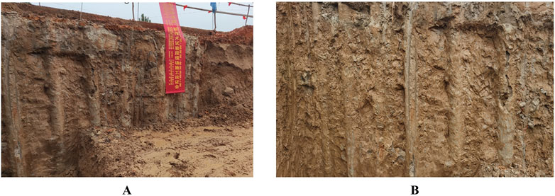
Through the above numerical simulation, the quality of walls is better when the hole diameter is 0.6 m, the grouting pressure is 32 MPa, and the hole spacing is 0.8 m. These parameters were used in the field for the verification test. The method of combining wall excavation detection with core drilling coefficient detection was adopted for the quality inspection and evaluation of cut off walls. Wall excavation was carried out at intervals of 500 m along the wall axis, with each excavation area measuring 3–5 m in length and 2.5–4.0 m in depth. As shown in Figure 8, the cut off wall in the test section was continuous and intact, with no leak spray. By measuring the width of the cut off wall at different locations, the average thickness of the wall was obtained as 38 cm, which is in good agreement with the corresponding wall thickness of 41 cm under the corresponding conditions obtained from the numerical simulation results.
After 28 days of construction, core holes were drilled at 500 m intervals along the axis of the wall. The core drilled samples of the walls in the test section are shown in Figure 9A. The sample core was intact and the surface was smooth. The coefficient of permeability was tested using a SS-2.5 Penetrometer, as shown in Figure 9B. Two core holes were drilled on site, A and B, and three sample cores were taken from each hole to test the permeability coefficient. The core permeability coefficients were listed in Table 3. The average values of permeability coefficient of hole A and hole B were 8.33 × 10⁻⁷ cm/s and 9.12 × 10⁻⁷ cm/s, respectively, which are less than the design value (1–9) × 10–6 cm/s. Qualitative excavation test results and qualitative core permeability test results verified the reliability of the above numerical simulation results.
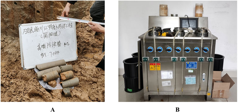
Figure 9. Core drilling and permeability coefficient testing equipment. (A) Core drilled samples. (B) SS-2.5 Penetrometer.
5 Conclusion
The present study established a two-dimensional plane strain model for the simulation of the construction of cut off walls using the high pressure jet grouting based on the SPH method. The influence of hole diameter, grouting pressure and hole spacing on the process of soil failure and the quality of the wall was analyzed systematically. Combined with the construction test of cut off walls using high spray method in Luotang Township, Jiangxi Province, China, the simulation results of this article were preliminarily verified. The main conclusions are as follows:
(1) The high-speed sprayed cement slurry will not initially cause failure to the soil after acting on the hole wall, but bounce off the hole wall and fell into the hole. Under the continuous action of high-speed cement slurry, radial cracks will appear around the wall of the grouting hole. The slurry with a certain velocity enters the radial cracks, causing them to extend towards the front grouted hole. The grouting hole will be connected to the front grouted hole to form a continuous cut off wall.
(2) As the hole spacing increased, the propagation direction of fractures in the soil under the high-speed slurry gradually deviated from the direction of the inter-hole centerline. The influence of hole diameter and spacing on the quality of cut off walls is more significant. Reducing the hole diameter and grouting pressure or increasing the hole spacing will lower the quality of cut off walls. The quality of walls is better when the hole diameter is 0.6 m, the grouting pressure is 32 MPa, and the hole spacing is 0.8 m.
(3) Relying on the flood control project in Luotang Township, Jiangxi Province, China, the method of combining wall excavation detection with core drilling coefficient detection was adopted for the quality inspection and evaluation of cut off walls. The cut off wall in the test section was continuous and intact, with no leak spray. The average values of permeability coefficient of the two sets of samples are less than the design value. Qualitative excavation test results and qualitative core permeability test results verified the reliability of the above numerical simulation results.
Data availability statement
Data will be made available on request.
Author contributions
DL: Writing–original draft, Writing–review and editing. Z-wY: Resources, Supervision, Validation, Writing–review and editing. W-jX: Software, Writing–review and editing. J-lG: Data curation, Writing–review and editing. S-tH: Methodology, Writing–review and editing. YL: Conceptualization, Writing–review and editing. FC: Visualization, Writing–review and editing.
Funding
The author(s) declare that financial support was received for the research, authorship, and/or publication of this article. The authors declare that financial support was received for the research, authorship, and/or publication of this article. This work is supported by The Water Conservancy Technology Demonstration Project of the Ministry of Water Resources (SF-TJ-202417), the Open Foundation of Jiangxi Hydraulic Safety Engineering Technology Research Center (2022SKSG02), Jiangxi Provincial Department of water resources Foundation (202324YBKT04, 202425TGKT01).
Acknowledgments
The authors wish to express they’re thanks to the supporter.
Conflict of interest
The authors declare that the research was conducted in the absence of any commercial or financial relationships that could be construed as a potential conflict of interest.
Publisher’s note
All claims expressed in this article are solely those of the authors and do not necessarily represent those of their affiliated organizations, or those of the publisher, the editors and the reviewers. Any product that may be evaluated in this article, or claim that may be made by its manufacturer, is not guaranteed or endorsed by the publisher.
References
Brown, A. J., and Bruggemann, D. A. (2002). Arminou Dam, Cyprus, and construction joints in diaphragm cut-off walls. Geotechnique 52 (1), 3–13. doi:10.1680/geot.52.1.3.40823
Cheng, H. Z., Li, W. T., Chen, R. P., and Yi, Y. L. (2022). Workability study of sand-bentonite-cement mixtures for construction of two-phase cut-off wall. Constr. Build. Mater. 345, 128058. doi:10.1016/j.conbuildmat.2022.128058
Dai, W. K., Liang, L., and Zhang, B. J. (2020). Firefly optimization algorithm for the prediction of uplift due to high-pressure jet grouting. Adv. Civ. Eng., 8833784. doi:10.1155/2020/8833784
Gingold, R. A., and Monaghan, J. J. (1977). Smoothed particle hydrodynamics: theory and application to non-spherical stars. Mon. Notices R. Astronomical Soc. 181, 375–389. doi:10.1093/mnras/181.3.375
Guo, H. (2021). High pressure jet grouting mechanism test and numerical simulation research. Beijing, China: Beijing Jiaotong University.
Heidarzadeh, M., Mirghasemi, A. A., Niroomand, H., and Eslamin, F. (2019). Construction and performance of the Karkheh dam complementary cut-off wall: an innovative engineering solution. Int. J. Civ. Eng. 17 (6B), 859–869. doi:10.1007/s40999-018-0370-4
Huang, B. D. (2010). Discussion on factors influencing quality of high pressure jet grouting diaphragm wall and preventive measures. Yellow River 41 (05), 58–61. doi:10.3969/j.issn.1001-4179.2010.05.022
Li, P. P., Huang, X., Lu, F., Qiu, W. E., Liu, H., Li, L. L., et al. (2023). Experimental investigation on the reinforcement of a high-pressure jet grouting pile for an ultra-shallow tunnel in a strongly weathered stratum. Front. Earth Sci. 10, 1040461. doi:10.3389/feart.2022.1040461
Liu, D., Xie, W. J., Gao, J. L., Hu, S. T., Chen, M., Li, Y., et al. (2022). Study on the construction method and effects of ipsilateral, multi-nozzle, high-pressure jet grouting cut-off wall. Sustainability 14 (16), 10383. doi:10.3390/su141610383
Livermore Software Technology Corporation (2003). LS-DYNA theoretical manual. California: Livermore Software Technology Corporation.
Monaghan, J. J. (2005). Smoothed particle hydrodynamics. Rep. Prog. Phys. 68 (8), 1703–1759. doi:10.1088/0034-4885/68/8/R01
Wang, F. M., Li, M. J., Fang, H. Y., and Xue, B. H. (2019). Analysis of polymer cut-off wall of Yellow River dyke. Yellow River 41 (10), 48–52. doi:10.3969/j.issn.1000-1379.2019.10.009
Wang, K., Li, Z. P., Zheng, H., Xu, X. Z., and He, H. F. (2021). A theoretical model for estimating the water-tightness of jet-grouted cut-off walls with geometric imperfections. Comput. Geotech. 138, 104316. doi:10.1016/j.compgeo.2021.104316
Wei, X. Y., Zhao, Z. Y., and Gu, J. (2009). Numerical simulations of rock mass damage induced by underground explosion. Int. J. Rock Mech. Min. Sci. 46 (7), 1206–1213. doi:10.1016/j.ijrmms.2009.02.007
Wu, K., Chen, R. G., Gu, H. R., Yuan, J. J., and Qian, X. Q. (2023). Experimental study on seepage control performance of high pressure jet grouting pile using grouting material in water-rich sand layer. Chin. J. Undergr. Sp. Eng. 19 (02), 533–540.
Wu, S. H., Lu, Y., Wu, S., Yin, Y. C., Zhang, T., and Yue, Q. J. (2024). Simulation analysis of jet soil-breaking based on arbitrary Lagrange-Euler method. J. Vib. Shock 43 (13), 162–171. doi:10.13465/j.cnki.jvs.2024.13.018
Wu, Y. X., Shen, S. L., Yin, Z. Y., and Xu, Y. S. (2015). Characteristics of groundwater seepage with cut-off wall in gravel aquifer. II: numerical analysis. Can. Geotech. J. 52 (10), 1539–1549. doi:10.1139/cgj-2014-0289
Yang, S. Q. (2010). Application of paste-slurry and high pressure jet grouting in cofferdam seepage control. Yangtze River 41 (24), 58–62. doi:10.16232/j.cnki.1001-4179.2010.24.012
Yang, Y., Zhong, Q. P., Zhang, G. L., and Zhao, X. Y. (2021). Selection and research on key parameters of high pressure jet grouting construction. Tech. Superv. Water Resour. 10, 182–185. doi:10.3969/j.issn.1008-1305.2021.10.045
Yang, Z. (2008). Jet grouting and construction of the mechanism of strengthening anti-technology research. Central south university.
Yu, X., Kong, X. J., Zou, D. G., Zhou, Y., and Hu, Z. Q. (2015). Linear elastic and plastic-damage analyses of a concrete cut-off wall constructed in deep overburden. Comput. Geotech. 69, 462–473. doi:10.1016/j.compgeo.2015.05.015
Zhang, F., Li, J., Deng, Y. F., and Xu, C. L. (2024). Numerical investigation of mixing process of high-pressure jet-cutting clay by water-air coaxial nozzle considering soil rheological properties. Comput. Geotech. 165, 105878. doi:10.1016/j.compgeo.2023.105878
Zhang, S. B., Kong, X. Z., Fang, Q., and Peng, Y. (2023). The maximum penetration depth of hypervelocity projectile penetration into concrete targets: experimental and numerical investigation. Int. J. Impact Eng. 181, 104734. doi:10.1016/j.ijimpeng.2023.104734
Keywords: cut off wall, high-pressure jet grouting, SPH method, hole spacing, grouting pressure, hole diameter
Citation: Liu D, Ye Z-w, Xie W-j, Gao J-l, Hu S-t, Li Y and Chen F (2024) Numerical simulation study on the construction of cut off walls using high-pressure jet grouting based on SPH method. Front. Earth Sci. 12:1491583. doi: 10.3389/feart.2024.1491583
Received: 05 September 2024; Accepted: 06 November 2024;
Published: 19 November 2024.
Edited by:
Yifei Sun, Taiyuan University of Technology, ChinaCopyright © 2024 Liu, Ye, Xie, Gao, Hu, Li and Chen. This is an open-access article distributed under the terms of the Creative Commons Attribution License (CC BY). The use, distribution or reproduction in other forums is permitted, provided the original author(s) and the copyright owner(s) are credited and that the original publication in this journal is cited, in accordance with accepted academic practice. No use, distribution or reproduction is permitted which does not comply with these terms.
*Correspondence: Zhi-wei Ye, eWV6aGl3ZWlAbmN1LmVkdS5jbg==
 Da Liu
 Wei-jiang Xie
