- 1Xi’an Research Institute, China Coal Technology and Engineering Group Corp., Xi’an, China
- 2College of Energy Science and Engineering, Xi’an University of Science and Technology, Xi’an, China
- 3Xi’an CCTEG Transparent Geology Technology Co., Ltd., Xi’an, China
- 4China Coal Research Institute, Beijing, China
Introduction: To develop a small-scale regional microseismic location model for coal mines and enhance the accuracy of microseismic location at the bottom plate,this article proposes a high-precision location algorithm for 3D-Fast Sweeping Method (3D-FSM) seismic sources under time quality constraints.
Methods: The study investigates the numerical simulation of microseismic location accuracy on coal seam floor, considering various observation systems, arrival time picking errors, and wave velocity discrepancies. The algorithm employs a VGG-16 deep learning network to train and establish a quality control model for P-wave pickup values; Next, utilizing the 3D-FSM framework, it calculate the seismic wave travel time field and applies Fermat’s principle for each detection point, as well as the reversible principle of elastic wave propagation path. This allows for the determination of the spatial path and travel time from any potential source point to the detection point. Finally, the algorithm scans each computational node, using the controlled travel time difference to identify the source point corresponding to the smallest spatial node.
Results: The results indicate that the location error of the borehole tunnel observation system is smaller than that of the tunnel observation system. Specifically, with the borehole tunnel observation system, the variance in P-wave arrival time picking is 1 ms, and the wave velocity variance is 20 m/s2, demonstrating high accuracy.
Discussion: The findings suggest that the 3D-FSM seismic source location algorithm, under quality control, approaches the precision of manual location methods and exhibits high reliability, even when disregarding significant accuracy errors during the quality control location process.
1 Introduction
Disturbance-induced water hazard during coal seam floor mining represent a significant form of mine water damage. Statistics show that 60% of coal mines in China are at risk of such hazards, making it the country most ffected by coal seam floor water damage worldwide (Yang et al., 2022; Li et al., 2023b). In recent years, China has made substantial strides in evaluating, preventing, and issuing early warnings regarding water hazards associated with coal seam floors (Zhang et al., 2020; Xue et al., 2023). However, water hazard from the bottom plate still occurs occasionally, posing serious threats to miner safety. Accurate localization of microseismic events on the coal seam floor is crucial for understanding the spatiotemporal development of mining-induced fractures, which is vital for informing strategies to prevent and control water inrushes linked to coal mining activities. Microseismic location technology is widely utilized across various engineering fields to ensure the safety and stability of rock formations. Key applications include deep mineral resource extraction (Mngadi et al., 2019; Pan et al., 2020), excavation of deep-buried tunnel rock masses, maintenance of high and steep slope stability, and location the range of fracturing induced by water pressure (Samsonov et al., 2024; Xiang et al., 2023). In the mining field, micro-seismic location technology addresses a range of issues, including rock burst, mine tremors, roof and floor damage, coal pillar stability, coal and gas outburst, illegal mining activities, and coalbed methane development. The main research directions in microseismic data processing and interpretation focus on arrival time picking (Barthwal and Shcherbakov, 2024; Charles and Maochen, 2018; Qian et al., 2024), microseismic source localization (Cheng et al., 2018; Jiang R. et al., 2021; Sedghizadeh et al., 2023; Zhou et al., 2022), and microseismic source parameter inversion (Li et al., 2023a). Anikiev et al. (2022) used machine learning to analyze the noise and location network sensitivity in the arrival time to obtain the source location, and verified it with the localization of microseismic activity that occurred during actual hydraulic fracturing operations in the Akoma Basin, United States. Cheng et al. (2017) employed micro-seismic location technology to investigate the distribution patterns of micro-seismic events originating from the mining roof rock mass, both vertically and horizontally. He proposed a method to determine displacement angle using micro-seismic data, which was validated in Dongjiahe Coal Mine. Ma et al. (2020) established a microseismic location system in the Dongjiahe coal mine, applying moment tensor theory to deduce the source mechanism of floor micro-seismic anomalies and employing stress inversion method to identify underlying faults. Jiang et al. (2021b) proposed a low-dimensional dual-event joint localization method that simplifies high-dimensional inversion into a set of equations with only six parameters, selecting 2,000 P-wave arrival time combinations from over six sensors. Researchers at the Mining Seismic Acquisition System Institute of Yongshaba Mine in Guizhou Province conducted tests using two composite positions and analyzed data from eight blasting events, confirming the high positioning accuracy of the proposed method. Relative to the scale of coal mines, the depth of coal seam floor mining is relatively small. Numerous theoretical studies and practical location efforts have shown that the layout of observation systems, arrival time picking errors, and velocity model inaccuracies can significantly impact the accuracy of micro-seismic source localization.
In this paper, we propose a high-precision localization algorithm for 3D-FSM seismic sources, developed through an examination of numerical simulation that consider various factors affecting localization accuracy on coal seam floors. Research on the application of micro-seismic location for detecting water hazards at the bottom plate of the 81,307 coal mining face demonstrates that the 3D-FSM seismic source localization algorithm, when subjected to quality control, yields results comparable to manual localization in terms of reliability. However, significant localization accuracy errors may occur without proper consideration of time and quality control.
2 Development of simulation modeling
2.1 Principles of microseismic location
Source location is a fundamental tasks in microseismic monitoring, and the accuracy of this process directly impacts the subsequent analyses. Currently, various methods exist for source location, with the travel time differences method being the most widely adopted (Zhao et al., 2023). As shown in Figure 1, the spatial coordinate of the ith detector are represented as
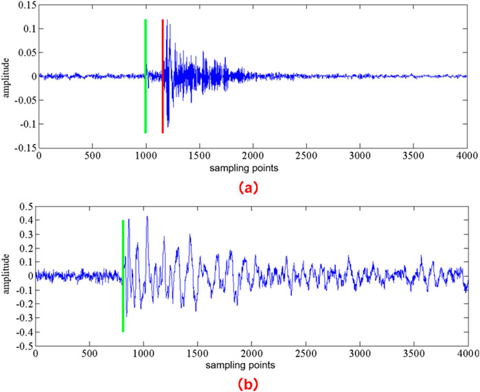
Figure 2. Time of P- and S wave of typical microseismic wave signals. (A) Both P-wave and S-wave oscillations are evident. (B) The situation where the S-wave oscillation is not obvious.
The source location aims to determine the spatial coordinates
where
Without considering errors associated with the velocity model, arrival time picking, and measurement of the location points, the micro-seismic event parameter
2.2 Numerical simulation experiment on microseismic location accuracy of coal seam floor
2.2.1 Simulation method for microseismic source location accuracy based on d-value theory
Kijko and Sciocatti (1995) conducted comprehensive research on microseismic location theory in order to optimize the spatial arrangement of mining seismic stations. They proposed the D-value theory to enhance microseismic observation systems (Zhao et al., 2022), as shown below.
The microseismic arrival time
where
The issue of microseismic location can be reformulated as the following mathematical optimization problems as shown in Equation 3:
where
Kijko and M Sciocatti believes that the effectiveness of an observation system should be determined by the covariance matrix of the parameter
where
The expression of function
where
The steps of the ellipsoid depicted in Equation 5 are proportional to
Disregarding error factors such as coordinate measurements of detection points and arrival time picking, the Equation 6 for seismic wave travel time is given by:
where
The covariance matrix
where k is a constant and A is a partial differential matrix.
According to the basic properties of the determinant,
Therefore, the minimization problem of
If
Considering the randomness of the source coordinates, the average value within the location range
Considering that the probability of microseismic events occurring at different points in the spatial domain
In the above derivation process, it is assumed that all n detectors in the microseismic observation system are triggered by one event. For all events, the partial derivative matrix A has the same number of rows, equal to the total number of microseismic detectors n. The fundamental assumption underlying this approach is that the energy emitted by microseismic events must be sufficiently substantial for all detectors to reliably capture the stress waves. To address this stringent assumption, Kijko and Sciocatti (1993) integrated Equation 12 within a certain range of seismic energy:
where
According to the basic theory of seismic wave propagation, both microseismic energy and the covariance matrix
where q is approximately equal to 2.
According to Rikitake (1976) derivation of seismic energy distribution, the probability density distribution function
where b is the b value related to magnitude m and the number of events in the Gutenberg Richter equation, and d is the d value in the relationship between seismic energy E and magnitude m shown in Equation 15:
where d equals 1.5, and the value of b depends on the specific mine, generally ranging from 0.6 to 1.2.
Based on the above factors, the criteria for determining the optimal observation system can be obtained shown in Equation 16:
where
The expected standard error diagram of microseismic event parameter
Due to the eigenvalues
Gong et al. (2010) proposed the calculation formula for seismic source error based on Equation 19:
where
2.2.2 Simulation of source location accuracy under different observation systems
Installing detectors in deep holes within the coal seam floor positions them in the rock layers beneath, bringing them closer to the target location area and potential micro-seismic events. Based on the theory of micro-seismic localization theory, this closer proximity is expected to enhance localization accuracy. However, installing detectors in deep boreholes is complex, non-recoverable, and results in high construction costs. To strike a balance between location costs and accuracy, we utilize the D-value optimization criterion to simulate the localization error of micro-seismic events under two observation systems: the bottom-plate-depth hole observation system and the tunnel observation system.
2.2.2.1 Microseismic location of tunnel observation system
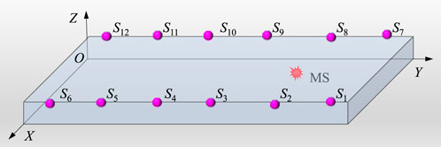
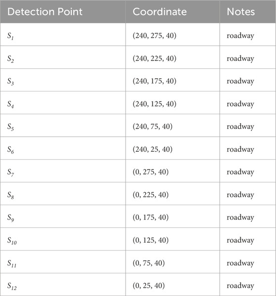
A coal seam floor seismic source location model was constructed as illustrated in Figure 3. The model has a Y-axis length of 300 m (representing the location length of the fully mechanized mining face floor), an X-axis width of 240 m (representing the width of the fully mechanized mining face), and a Z-axis height of 40 m (indicating the maximum depth of floor failure). The coordinate distribution of the observation system is shown in Table 1.
2.2.2.2 Microseismic location of the borehole tunnel observation system
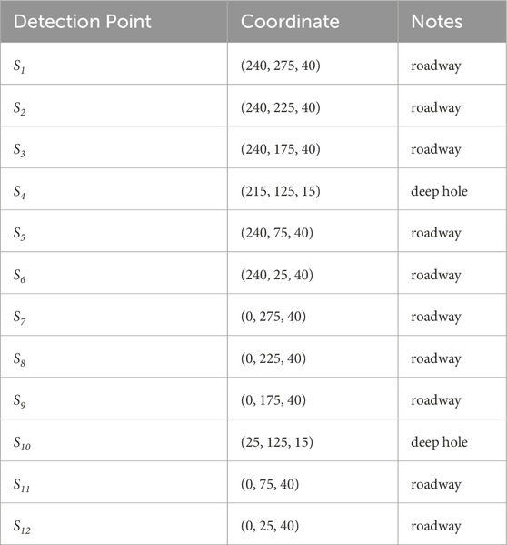
To enhance the accuracy of location coal seam floor mining damage, a borehole-tunnel observation system is proposed. This approach strategically optimizes the layout of the microseismic location system. “Lane” refers to the micro-seismic detector installed on the bottom anchor rods of the mine roadway, as illustrated in Figure 4A. “Hole” refers to the micro-seismic detectors placed in the deep boreholes in the floor, where the drilling axis forms a 135° angle with the coal slope of the working face and reaches a vertical depth of 25 m. The detectors are positioned at the bottom of the borehole and sealed with cement mortar, as shown in Figure 4B.
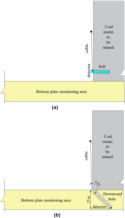
Figure 4. Detector layout method. (A) Installation of tunnel sensors. (B) Installation of bottom plate deep hole detectors.
A coal seam floor seismic source location model was constructed, as illustrated in Figure 5. The model features a Y-axis length of 300 m (representing the location length of the fully mechanized mining face floor), an X-axis width of 240 m (representing the width ofx the fully mechanized mining face), and a Z-axis height of 40 m (indicating the maximum depth of floor failure). The points S4 and S10 correspond to bottom plate deep holes, and the coordinates of each detection point are provided in Table 2.
2.2.2.3 Location accuracy simulation
The location range for micro-seismic events in coal seam floor mining is defined as {(x, y, z)|0<x<240∩ 0<y<300∩0<z<40}, with an average P-wave velocity of 3,000 m/s, a velocity variance of 100 m/s2, and an average picking error of 1 m at that time. The grid size is
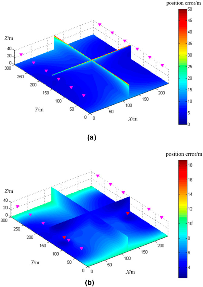
Figure 6. Simulation of microseismic location error of coal seam floor under different observation systems. (A) Distribution of location errors in the bottom plate seismic source of the tunnel observation system. (B) Distribution of bottom plate source location error in hole lane observation system.
Figure 6 shows that adding deep borehole detector on both sides of the coal mining face significantly enhances the location accuracy of micro-seismic events within the location area. The average location errors of micro-seismic events under the tunnel microseismic observation system and the combined borehole-tunnel observation system are 10.33 m and 5.63 m, respectively.
Based on the experimental results, we selected the borehole-tunnel observation system for microseismic location of the coal seam floor.
2.2.3 Simulation of source location accuracy under different picking errors at different arrival times
Building on the preferred borehole-tunnel observation system, we conducted simulations to assess the spatial localization accuracy of micro-seismic location at the wellbore joint bottom plate. The simulations were performed under three P-wave arrival time picking variances: 1 ms, 5 ms, and 10 ms, while keeping consistent parameters for location range, average P-wave velocity, and P-wave velocity variance. Results for the 1 ms variance are depicted in Figure 6B, and while results for the 5 ms and 10 ms variances are illustrated in Figure 7. With picking variances of 1 ms, 5 ms, and 10 ms, the average micro-seismic location accuracy were 5.63 m, 16.67 m, and 32.04 m, respectively.
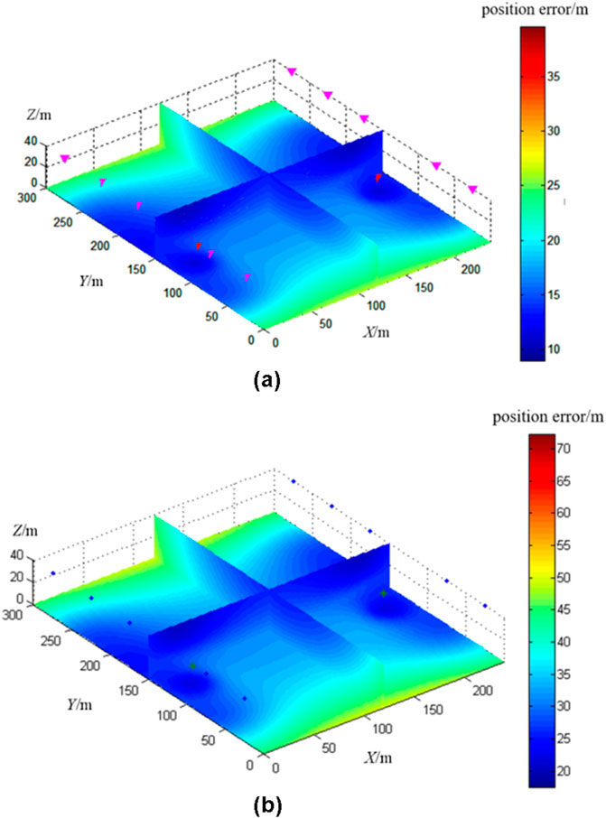
Figure 7. Simulation of coal seam floor source location error under different P-pick-up errors. (A) P-wave arrival time picking variance 5 m location accuracy. (B) P-wave arrival time picking variance 10ms location accuracy.
The experiment demonstrates that the precision of P-wave arrival time picking has a significant impact on micro-seismic localization accuracy. Enhancing source localization accuracy requires filtering out P-wave arrival time picks with lower precision before determining source location. To address this, this study applies deep learning techniques to identify and eliminate erroneous P-wave arrival time picks, ultimately improving the accuracy of microseismic source localization.
2.2.4 Simulation of source location accuracy under different wave velocity errors
Building on the selected borehole-tunnel observation system, simulation were conducted to assess the spatial location accuracy for micro-seismic location at the wellbore joint bottom plate under three conditions of P-wave velocity variance:500 m/s2, 200 m/s2, and 20 m/s2. The results of these simulations are presented in Figure 8.
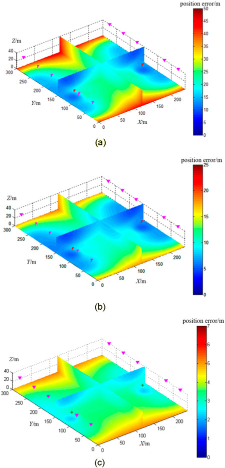
Figure 8. Cloud map of focal spatial location accuracy of combined well and hole bottom plate with different wave velocity errors. (A) P-wave velocity variance 500 m/s2. (B) P-wave velocity variance 200 m/s2. (C) P-wave velocity variance 20 m/s2.
According to the simulation results, when the P-wave velocity variance is 500 m/s2, the source location error in the location area ranges from 10 to 50 m, with an average location accuracy of 21.52 m, which does not meet the accuracy requirements of bottom plate source location. At a P-wave velocity variance of 200 m/s2, the average source location accuracy in the location area improves to 9.35 m; while a variance of 20 m/s2 further reduces the average error to 3.33 m. To reliably monitor micro-seismic events on the bottom plate, micro-seismic location at the well hole joint bottom plate must be based on a high-precision velocity model.
2.3 Quality control of microseismic pickup values
2.3.1 Convolutional neural network
CNNs are a prominent algorithm in deep learning, specifically a type of feedforward neural network known for its convolutional operations and deep structure. Since 2010, CNNs have achieved significant success in image and video recognition applications, including facial recognition, medical imaging, and autonomous driving. Recently, geophysicists have begun applying deep learning techniques, such as CNNs, in geophysical research. CNN models consist of input layers, multiple convolutional layers, pooling layers, fully connected layers, and output layers. An example architecture of a CNNs architecture is shown in Figure 9. The convolutional layers are responsible for feature extraction, pooling layers reduce image spatial dimensions, and fully connected layers establish connections between adjacent layers, respectively (Huang et al., 2018; Jafari et al., 2023; Viatkin et al., 2021).
2.3.2 P-wave pickup value dataset
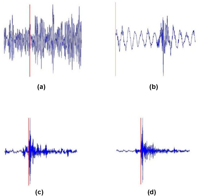
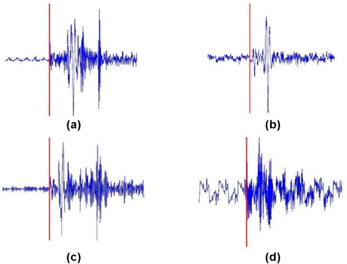
The purpose of quality control for P-wave arrival time picks is to use computer intelligence to distinguish between correct and incorrect values. Building large-scale training and testing datasets is essential for developing and evaluating models to control P-wave pick quality. Using micro-seismic location waveform data from a certain mine, the AIC algorithm and manual methods were applied to pick the P-wave arrival times of micro-seismic signals. Based on the picking accuracy for each micro-seismic waveform, correct and erroneous P-wave arrival times were identified. The results of automatic picking were saved as images (Figures 10, 11) to serve as input data for the CNNs. Figures 10A, B show typical low signal-to-noise ratio (SNR) signals with P-wave picking errors, commonly due to weak microseismic signals, long propagation distances, or detector failures. Figures 10C, D show incorrect arrival time picks values for medium to high SNR signals, often caused by strong energy of S-wave energy, which conventional algorithms struggle to separate from P-wave arrivals. Figure 11 shows an example of an accurate P-wave arrival time pick with a high SNR.
As shown in Table 3, this study used 13,540 data samples collected from micro-seismic location at the 81,307 working face of a certain mine. The dataset includes 6,720 correct and 6,820 incorrect P-wave picks, with an approximate 1:1 ratio. The dataset was divided training and test sets at a 7:3 ratio, with both correct and incorrect picks proportionately distributed. The training set contains a total of 9,478 samples, comprising 4,704 correct and 4,774 incorrect picks. The test set includes 4,062 samples, with 2,016 correct and 2,046 incorrect P-wave picks.
2.3.3 Training of P-wave pickup value quality control model
To compare the differences in identifying incorrect P-wave pickup values among different convolutional neural network models, this study used four network models to train P-wave pickup value quality control models, including VGG-16, ResNet-50, VGG-SENet, and ResNet-SENet.
This study employs four convolutional neural network models—VGG-16, ResNet-50, VGG-SENet, and ResNet-SENet—to train P-wave pickup quality control models, allowing for a comparative analysis of each model’s effectiveness in identifying incorrect P-wave pickup values.
The input P-pickup image is set to a width and height of 128 pixels. During the training process, adjust the learning rate and evaluate the model performance by location val-acc (validation accuracy). The parameters that need to be optimized include patient, factor, and minimum learning rate (min_lr). Set the initial patient=2, factor=0.1, and min_lr=1e−10. The training accuracy curves of four convolutional neural network models are shown in Figure 12.

Figure 12. Training accuracy curves of VGG-16 ResNet-50 VGG-SENet and ResNet-SENet models. (A) VGG-16 accuracy comparison. (B) ResNet-50 accuracy comparison. (C) VGG-SENet accuracy comparison. (D) ResNet-SENet accuracy comparison.
The input P-wave pickup images are configured to a resolution of 128x128 pixels. During training, the learning rate is adjusted, and model performance is evaluated by tracking validation accuracy (val-acc). Key parameters to optimize include “patience,” “factor,” and “minimum learning rate (min_lr),” initially set to ‘patience=2′, ‘factor=0.1′, and ‘min_lr=1e-10`. The training accuracy curves for the four convolutional neural network models are illustrated in Figure 12.
The training results of four CNNs models are shown in Table 4. The accuracy scores for the VGG-16,ResNet-50,VGG-SENet, and ResNet-SENet models are 0.915, 0.821, 0.848, and 0.858, respectively, with corresponding precision scores of 0.905, 0.712, 0.733, and 0.802. Among these, the VGG-16 model achieved the highest accuracy and precision for P-wave pickup quality control. Therefore, this study chose the P-wave pickup quality control model trained on VGG-16.
2.4 A high-precision location algorithm for 3D-FSN seismic sources under time quality constraints
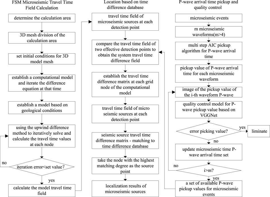
According to simulation assessing the micro-seismic location accuracy of mining-induced fractures at the bottom plate, the accuracy of the velocity model significantly affects the accuracy of the seismic source location. Given that the development depth of these fractures is typically within 30 m, it is essential to base the seismic source location on high-precision velocity models rather than simplified uniform models. Based on the above analysis, this study employs the FSM to locate seismic events at the bottom plate (Chen et al., 2015; Tro et al., 2023). The specific algorithm flowchart is illustrated in Figure 13. The fundamental idea involves first calculating the seismic wave travel time field of each detection point based on 3D-FSM. Next, based on Fermat’s principle and the principle of reversible elastic wave propagation, the spatial path and travel time from any potential source point to the detection point are obtained. Finally, each calculation node is scanned, using the travel time difference to identify the spatial node that corresponds to the earliest arrival time as the source point. The 3D-FSM source location algorithm offers advantages such as high computational accuracy, compatibility with complex velocity models, and rapid iteration speed.
Utilizing the principle of seismic wave propagation and source exchange, we calculate the travel time matrix for each grid node within the observation area. This is accomplished by considering each detector in the observation system as a virtual source. By performing pairwise subtraction of these matrices, we derive the travel time difference matrix for each grid point. This information is then compiled into a comprehensive travel time difference database.
Source location involves matching the travel time difference matrix of the source to be inverted with the arrival time difference database. Note that
where
3 Research on high-precision location application of microseismic events caused by bottom plate mining
3.1 General situation
The 81,307 fully mechanized mining face in a coal mine in Shanxi province is used to mine 8# coal, with a strike length of 2,491 m and a dip length of 240 m. During the mining period, the west side of the 81,307 working face adjoins the undeveloped 81,308 working face, while the east side borders the fully mined 81,306 working face. The thickness of the coal seam in the 81,307 working face varies from 4.5 to 9.2 m, with an average thickness of 6.8 m, gradually increasing from the cutting eye toward the retreat channel. The coal dip at an angle of 2°–5°, typically interbedded with an average of 3 layers of gangue, primarily consisting of mudstone. The maximum thickness of a single layer of interbedded gangue reaches 0.9 m. Beneath the 8 # coal seam lies the main 11# coal seam, which is part of the Taiyuan Formation of the Carboniferous-Permian period, with an average thickness of 7.36 m. The Ordovician limestone aquifer below the 11# coal seam serves as the primary aquifer affecting the mining operations. The water level elevation of the Ordovician limestone confined aquifer is +839 m. The average distance from the top interface of the Ordovician aquifer to the 8# coal seam is 112.5 m, while the average distance to the 11# coal seam is 66.7 m. The elevation of the bottom plate of the 81,307 working face is lower than the water head elevation of the Ordovician limestone, presenting a challenge of mining under pressure. The 11# coal seam lies almost entirely beneath the water head of the Ordovician limestone. During the mining process of the 8# coal seam, no structural water transmission phenomena, such as faults, have been observed. However, during the development of the 11# coal seam, multiple small faults were encountered, accompanied by water hazards from the bottom plate of the Ordovician limestone, which poses significant challenges for water prevention and control. At present, the degree of cracks development in the coal seam floor and other related issues remains unclear in the mine. Therefore, microseismic location has been carried out in the 81,307 working face to investigate the evolution of disturbance and damage in the floor rock layer during coal seam mining, thereby providing a scientific basis and experience for the safe mining of the 8# coal seam and the underlying 11# coal seam.
3.2 Layout of microseismic location system for working face
Based on the optimization research results of the micro-seismic observation system, location is conducted using the borehole tunnel observation system. The detectors in the tunnel are positioned on the anchor rods of the coal wall side, with the deep hole axis oriented at a 135° angle to the coal wall of the working face, reaching a vertical depth of 25 m. The detectors are installed at the bottom of the holes and sealed with cement mortar.
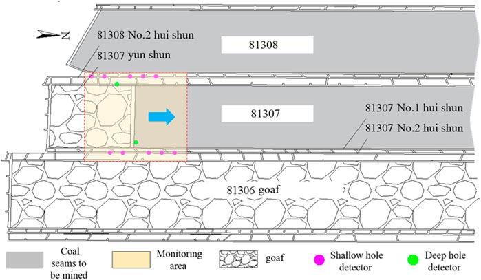
The micro-seismic location system for the bottom plate of the 81,307 working face consists of two location stations, located in the 81,308 No.2 return air channel and the 81,307 No.2 return air channel, respectively. The location substation in the 81,308 No.2 return air channel is connected to six sensors, which include five detectors positioned on the coal side of the 81,308 No.2 channel and one deep hole detector located in the 81,307 glue transportation channel. The sensors are spaced horizontally 40–60 m apart. Similarly, the location substation in the 81,308 No.2 return air channel is also connected to six sensors, comprising five detectors on the coal side of the 81,307 No.2 channel and one deep hole detector in the 81,307 No.1 return air channel, with the same horizontal spacing. To monitor the damage to the bottom plate, a rolling method is employed: as the working face advances, the detectors in the rear No. 81,308 and No. 81,307 coal seams are relocated to the unexplored area along the mining direction. The deep hole detectors in the No.81,307 rubber transportation channel and No.1 return air channel remain in place, with new location points established in these two tunnels. The detectors in the tunnels and deep boreholes form a three-dimensional micro-seismic location network that dynamically tracks the development of mining-induced fractures in the coal seam floor, spanning from 150 m behind the mining face to 150 m in front of the working face. Figure 14 illustrates a schematic diagram of the micro-seismic location system as of mid-May 2019.
3.3 Typical microseismic event location
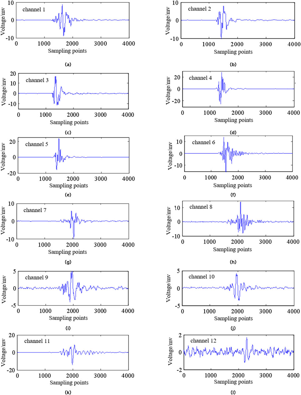
Figure 15 presents the 12 channel signals of the micro-seismic event monitored on 28 June 2019, at 11:41:50. For ease of reference, this event is designated as E20190628-541. With the exception of channel 12, which exhibits a low SNR, the quality of the micro-seismic signals collected from the other 11 channels is very high, displaying clear oscillations in all P-waves and some S-waves. The VGG-16 pickup value quality control algorithm, derived from previous training, is employed to assess the pickup values of micro-seismic events. The resulting discrimination vector is {1 1 1 1 1 1 1 1 1 1 1 1 0}, indicating that the first 11 channel waveforms have valid pickup values, while the 12th pickup value is deemed incorrect and unavailable. The algorithm’s discrimination results are accurate.
Using the aforementioned algorithm for source location, the arrival time of waves 1–11# was processed, resulting in a pickup at P1=(9334.92, 9938.27, 794.42). For waves 1–12#, the pickup resulted in P2=(9395.19, 9978.35, 553.48). In contrast, the manually picked arrival time yielded P3=(9337.32, 9936.29, 793.14). It can be concluded that P3 is closest to the true source point, while P1 and are relatively close to P3. However, P2 is significantly further from P3 and lies outside the range of coal mining disturbance, indicating it can be regarded as a location error.
3.4 Spatial distribution pattern of bottom plate microseismic events
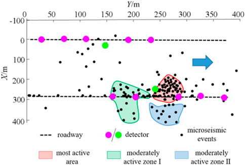
From May 2019 to June 2019, the micro-seismic location system recorded a total of 235 strong micro-seismic events from the bottom plate. The XY and XZ views of the distribution of these micro-seismic events are presented in Figures 16, 17, respectively. The XY view reveals that the micro-seismic events are mainly concentrated near the return airway of the 81,307 working face, within an approximate range of 150 m. In the XZ view, it is evident that the micro-seismic events mainly extend to a depth of 32 m below the coal seam floor. The rupture zone is mainly localized on the return airway side of the 81,307 working face, extending toward the middle of the working face at an inclination angle of 16.5°, with a depth of 32 m below the coal seam floor. Conversely, there are fewer micro-seismic events observed on the floor of the intake airway side of the 81,307 working face. Analysis indicates that the return air roadway of the 81,307 working face is situated near the goal of the 81,308 working face. During the mining process of the 81,307 working face, cracks in the bottom plate of the 81,306 working face rapidly developed due to secondary mining stress, resulting in the concentration of micro-seismic events primarily on one side of the return air roadway.
3.4.1 Characteristics of bottom plate failure along the strike direction
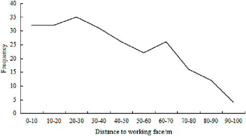
The frequency chart of micro-seismic events in front of the coal wall in the 81,307 working face is shown in Figure 18. Within a range of 0–40 m in front of the coal wall, micro-seismic events account for 55% of the total, with their frequency remaining relatively stable. In the range of 40–70 m, the occurrence of micro-seismic events gradually decrease. Beyond 70 m in front of the coal wall, there is a sharp decline in the number of micro-seismic events.
3.4.2 Characteristics of failure along the inclined bottom plate
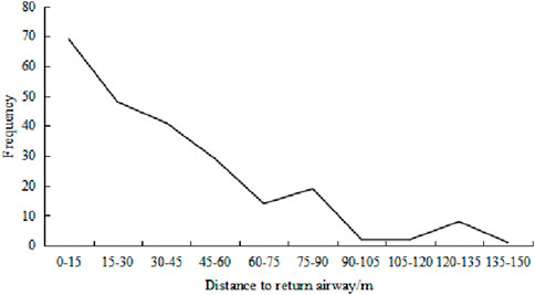
The trend chart showing the distance from the bottom plate micro-seismic event to the return airway plane of the 81,307 working face is shown in Figure 19. Micro-seismic events are mainly concentrated within 90 m of the second side of the return airway, accounting for 94% of the events in this area. As the distance from the return airway increases, the number of micro-seismic events decreases sharply.
3.4.3 Characteristics of failure along the depth of the bottom plate
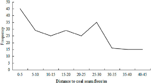
The trend chart depicting the distance from the coal seam floor micro-seismic events to the coal seam floor of the 81,307 working face is shown in Figure 20. The micro-seismic events related to the coal seam floor are primarily concentrated in the area more than 30 m below the coal seam, accounts for 80% of the total events. In contrast, there are significantly fewer micro-seismic events observed in the area further than 30 m below the coal seam floor.
4 Conclusion
With Liu et al. (2022) Compared with the traditional microseismic positioning studied, in order to enhance the localization accuracy of microseismic events in coal seam floor mining, this study employed theoretical analysis and numerical simulation to investigate the impact of various factors on localization precision. These factors include different observation systems, errors in arrival time picking, and inaccuracies in the wave velocity model. Consequently, the study optimized the bottom plate microseismic location observation system and developed a deep learning-based quality control algorithm for the arrival time picking values of microseismic waveforms. Ultimately, a high-precision localization method for 3D-FSM seismic sources under arrival time quality constraints was proposed. Additionally, research was conducted on the application of these methods to bottom plate microseismic events. The main conclusions are as follows:
•A simulation study on the spatial location accuracy of bottom plate microseismic location was conducted using the theory of optimizing the D-value of seismic source location. The optimized hole-tunnel joint micro-seismic observation system was developed, highlighting the importance of eliminating erroneous picking values and utilizing high-precision velocity models for accurate bottom plate microseismic event location.
•A quality control method for P-wave pickup values based on deep learning was proposed, utilizing a VGG-16 network for training. The trained model achieved the highest recognition accuracy, successfully identify 95% of incorrect pickup values.
•A 3D-FSM source location algorithm incorporating quality control was proposed, demonstrating high computational accuracy, suitability for complex velocity models, and fast iteration speed.
•When subjected to quality control, the algorithm produces results comparable to manual localization in terms of reliability. However, without considering time and quality control, significant errors in localization accuracy may occur.
•The next step will be to further investigate and demonstrate the effectiveness of deep learning in data processing for earthquake source localization.
Data availability statement
The original contributions presented in the study are included in the article/supplementary material, further inquiries can be directed to the corresponding author.
Author contributions
XW: Data curation, Funding acquisition, Methodology, Resources, Software, Writing–original draft, Writing–review and editing. QX: Writing–review and editing, Formal Analysis. JY: Software, Writing–review and editing, Resources.
Funding
The author(s) declare that financial support was received for the research, authorship, and/or publication of this article.This paragraph financially supported by the National Key Research and Development Program Tasks of China (2023YFC3008903-02); the National The General Program of the National Natural Science Foundation of China under Grant (42074175); Science and Technology Innovation Fund Project of CCTEGXIAN (2023XAYJS26).
Conflict of interest
Authors XW, QX, and JY were employed by China Coal Technology and Engineering Group Corp. Authors QX and JY were employed by Xi’an CCTEG Transparent Geology Technology Co., Ltd.
Publisher’s note
All claims expressed in this article are solely those of the authors and do not necessarily represent those of their affiliated organizations, or those of the publisher, the editors and the reviewers. Any product that may be evaluated in this article, or claim that may be made by its manufacturer, is not guaranteed or endorsed by the publisher.
References
Anikiev, D., Waheed, U. B., Staněk, F., Alexandrov, D., Hao, Q., Iqbal, N., et al. (2022). Traveltime-based microseismic event location using artificial neural network. Front. Earth Sci. 10, 1046258. doi:10.3389/feart.2022.1046258
Barthwal, H., and Shcherbakov, R. (2024). Unsupervised clustering of mining-induced microseismicity provides insights into source mechanisms. Int. J. Rock Mech. Min. Sci. 183, 105905. doi:10.1016/j.ijrmms.2024.105905
Charles, M., and Maochen, G. (2018). Enhancing manual P-phase arrival detection and automatic onset time picking in a noisy microseismic data in underground mines. Int. J. Min. Sci. Technol. 28, 691–699. doi:10.1016/j.ijmst.2017.05.024
Chen, W., Chou, C., and Kao, C. (2015). Erratum to: lax–friedrichs multigrid fast sweeping methods for steady state problems for hyperbolic conservation laws. J. Sci. Comput. 64, 619. doi:10.1007/s10915-015-0025-4
Cheng, G., Ma, T., Tang, C., Liu, H., and Wang, S. (2017). A zoning model for coal mining - induced strata movement based on microseismic monitoring. Int. J. Rock Mech. Min. Sci. 94, 123–138. doi:10.1016/j.ijrmms.2017.03.001
Cheng, J., Song, G., Sun, X., Wen, L., and Li, F. (2018). Research developments and prospects on microseismic source location in mines. Engineering 4, 653–660. doi:10.1016/j.eng.2018.08.004
Gong, S.-Y., Dou, L.-M., Cao, A.-Y., He, H., Du, T.-T., and Jiang, H. (2010). Study on optimal configuration of seismological observation network for coal mine. Chinese Journal of Geophysics (in Chinese) 53 (2), 457–465. doi:10.3969/j.issn.0001-5733.2010.02.025
Huang, L., Li, J., Hao, H., and Li, X. (2018). Micro-seismic event detection and location in underground mines by using Convolutional Neural Networks (CNN) and deep learning. Tunn. Undergr. Space Technol. 81, 265–276. doi:10.1016/j.tust.2018.07.006
Jafari, A., Alesheikh, A., Rezaie, F., Panahi, M., Shahsavar, S., Lee, M., et al. (2023). Enhancing a convolutional neural network model for land subsidence susceptibility mapping using hybrid meta-heuristic algorithms. Int. J. Coal Geol. 277, 104350. doi:10.1016/j.coal.2023.104350
Jiang, C., Liu, C., and Shang, X. (2021b). Double event joint location method considering P-wave arrival time system errors. Soil Dyn. Earthq. Eng. 149, 106890. doi:10.1016/j.soildyn.2021.106890
Jiang, R., Dai, F., Liu, Y., and Li, A. (2021a). Fast marching method for microseismic source location in cavern-containing rockmass: performance analysis and engineering application. Engineering 7, 1023–1034. doi:10.1016/j.eng.2020.10.019
John, R. C. St., and Draper, N. R. (1975). D-optimality for regression designs: a review. Technometrics 17 (1), 15–23. doi:10.1080/00401706.1975.10489266
Kijko, A., and Sciocatti, M. (1995). Optimal spatial distribution of seismic stations in mines. International Journal of Rock Mechanics and Mining Sciences and Geomechanics Abstracts 32, 607–615. doi:10.1016/0148-9062(94)00052-5
Kijko, A., and Sciocatti, M. (1993). Optimum spatial distribution of seismic stations. In Guide io Seismic Monitoring in Mines. Welkom: ISS International.
Li, W., Li, Q., Hu, Q., Qian, Y., Yang, H., Jiang, Z., et al. (2023a). Real-time microseismic evaluation of coalbed methane reservoir stimulation based on improved metaheuristic inversion strategy. Gas Sci. Eng. 119, 205151. doi:10.1016/j.jgsce.2023.205151
Liu, H., huang, H., Zhang, P., Li, L., Hou, J., Zhang, L., et al. (2022). Propagation path tracing of hydraulically created fractures based on microseismic monitoring. Front. Earth Sci. 10, 952694. doi:10.3389/feart.2022.952694
Li, Z., Ren, T., Black, D., Qiao, M., Abedin, I., Juric, J., et al. (2023b). In-situ gas contents of a multi-section coal seam in Sydney basin for coal and gas outburst management. Int. J. Coal Sci. and Technol. 10 (62), 62–13. doi:10.1007/s40789-023-00614-4
Ma, K., Sun, X., Tang, C., Yuan, F., Peng, Y., Liu, K., et al. (2020). An early warning method for water inrush in Dongjiahe coal mine based on microseismic moment tensor. J. Central South Univ. 27, 3133–3148. doi:10.1007/s11771-020-4534-4
Mngadi, S. B., Durrheim, R. J., Manzi, M. S. D., Ogasawara, H., Yabe, Y., Yilmaz, H., et al. (2019). Integration of underground mapping, petrology, and high-resolution microseismicity analysis to characterise weak geotechnical zones in deep South African gold mines. Int. J. Rock Mech. Min. Sci. 114, 79–91. doi:10.1016/j.ijrmms.2018.10.003
Pan, W., Pan, W., Luo, J., Fan, L., Li, S., and Erdenebileg, U. (2020). Slope stability of increasing height and expanding capacity of south dumping site of Hesgoula coal mine: a case study. Int. J. Coal Sci. and Technol. 8, 427–440. doi:10.1007/s40789-020-00335-y
Qian, Y., Li, Q., Liang, Y., Hu, Q., Li, W., Li, J., et al. (2024). Evaluation of hydraulic fracturing in coal seam using ground microseismic monitoring and source location. Rock Mech. Rock Eng. 57, 679–694. doi:10.1007/s00603-023-03577-9
Rikitake, T. (1976). Recurrence of great earthquakes at subduction zones. Tectonophysics 35, 335–362. doi:10.1016/0040-1951(76)90075-5
Samsonov, S. V., Feng, W., Blais-Stevens, A., and Eaton, D. W. (2024). Ground deformation due to natural resource extraction in the Western Canada Sedimentary Basin. Remote Sens. Appl. Soc. Environ. 32, 101159. doi:10.1016/j.rsase.2024.101159
Sedghizadeh, M., van den Berghe, M., and Shcherbakov, R. (2023). Statistical and clustering analysis of microseismicity from a Saskatchewan potash mine. Front. Appl. Math. Stat. 9, 1126952. doi:10.3389/fams.2023.1126952
Tro, S., Evans, M., Aslam, T., Lazano, E., and Culp, D. (2023). A second-order distributed memory parallel fast sweeping method for the Eikonal equation. J. Comput. Phys. 474, 111785. doi:10.1016/j.jcp.2022.111785
Viatkin, D., Garcia-Zapirain, B., Méndez-Zorrilla, A., and Zakharov, M. (2021). Deep learning approach for prediction of critical temperature of superconductor materials described by chemical formulas. Front. Mater 8, 714752. doi:10.3389/fmats.2021.714752
Xiang, Z., Zhen, R., Xu, Y., Wang, S., Ao, X., Chen, Z., et al. (2023). A numerical pressure transient model of fractured well with complex fractures of tight gas reservoirs considering gas-water two phase by EDFM. Geoenergy Sci. Eng. 231, 212286. doi:10.1016/j.geoen.2023.212286
Xue, Y., Zhu, S., and Qiu, H. (2023). Refinement study on the water-inrush risk of close-distance thin coal seam mining with pressure in the lower coal seam. Mine Water Environ. 42, 670–686. doi:10.1007/s10230-023-00965-z
Yang, H., Liu, S., and Yang, C. (2022). Dynamic monitoring of mining destruction on coal seam floor with constrained time-lapse resistivity imaging inversion. IEEE Access 10, 84799–84808. doi:10.1109/ACCESS.2022.3197759
Zhang, L., Ge, Z., Lu, Y., Zhou, Z., Xiao, S., and Deng, K. (2020). Tree-type boreholes in coal mines for enhancing permeability and methane drainage: theory and an industrial-scale field trial. Nat. Resour. Res. 29, 3197–3213. doi:10.1007/s11053-020-09654-y
Zhao, J., Jiang, Q., Liu, J., Chen, B., Pei, S., and Wang, Z. (2022). Rock fracturing observation based on microseismic location and borehole imaging: in situ investigation in a large underground cavern under high geostress. Tunn. Undergr. Space Technol. 126, 104549. doi:10.1016/j.tust.2022.104549
Zhao, Y., Yang, T., Hou, J., Jeon, S., Zhang, P., Wang, S., et al. (2023). A new rock fracture reconstruction method under the constraints of microseismic location and focal mechanism. Int. J. Rock Mech. Min. Sci. 170, 105493. doi:10.1016/j.ijrmms.2023.105493
Keywords: microseismic location, observation system, coal seam floor, arrival time picking, deep learning
Citation: Wu X, Xie Q and Yan J (2024) Research on microseismic source location based on time quality constraints. Front. Earth Sci. 12:1482158. doi: 10.3389/feart.2024.1482158
Received: 17 August 2024; Accepted: 29 October 2024;
Published: 21 November 2024.
Edited by:
Yongsheng Zhou, China Earthquake Administration, ChinaReviewed by:
Zhengzheng Cao, Henan Polytechnic University, ChinaYifang Chen, China Earthquake Administration, China
Copyright © 2024 Wu, Xie and Yan. This is an open-access article distributed under the terms of the Creative Commons Attribution License (CC BY). The use, distribution or reproduction in other forums is permitted, provided the original author(s) and the copyright owner(s) are credited and that the original publication in this journal is cited, in accordance with accepted academic practice. No use, distribution or reproduction is permitted which does not comply with these terms.
*Correspondence: Xuefei Wu, d3V4dWVmZWkxMjEyQDE2My5jb20=
 Xuefei Wu
 Qian Xie1,3
