 Zhijue Wu1,2
 Wen-Jing Niu
- 1School of Resources, Environment and Materials, Guangxi University, Nanning, China
- 2State Key Laboratory of Geomechanics and Geotechnical Engineering, Institute of Rock and Soil Mechanics, Chinese Academy of Sciences, Wuhan, China
- 3Bureau Public Works of Shenzhen Municipality, Shenzhen, Guangdong, China
Rockburst hazards occur sporadically after excavation of deep-buried hard rock tunnel. These failures in the surrounding rock masses are primarily induced by high ground stress, rendering conventional rock mass quality classification systems less applicable. This study discusses the limitations of existing rock mass quality classification systems when applied to deep-buried hard rock tunnels. A rockburst intensity tendency index, quantified through microseismic (MS) monitoring, is introduced and integrated into the RMR system, resulting in the development of an engineering rock mass quality classification system for deep-buried hard rock tunnels (DHRT-RMR). The development process involves: (i) selecting input parameters, including the rockburst intensity tendency index, and defining their weightings using the AHP; and (ii) establishing the DHRT-RMR system based on the principles of the RMR system. The rockburst intensity tendency index, DHRT-RMR system, and RMR system are then applied to two test sites selected from a tunnel in southwest China. Results indicate that the standalone use of RMR or the rockburst intensity tendency index is limited in engineering rock mass classification for deep-buried hard rock tunnels. However, the DHRT-RMR system can accurately assesses rock mass qualities in such tunnels.
1 Introduction
With rapid economic development in China, numerous large-scale rock engineering projects related to water conservancy, hydropower, underground mining, national defense, and railways have been continuously initiated at increasingly greater depths. Concurrently, problems such as rockburst, water-inrush, and significant deformation have intermittently occurred (She and Lin, 2014). In high ground stress environments, human excavations can produce strong disturbances, often resulting in unexpected failures and dynamically changing responses such as areal instabilities and collapses (Qian et al., 2012; Xu et al., 2024). These issues are particularly notable in deep-buried hard rock tunnels, where high-stress conditions prevail. Consequently, various accidental events such as rock block ejection and serious damage can occur during excavation, significantly impacting tunnel stability. Therefore, studying engineering rock mass quality classification for deep-buried hard rock tunnels is of profound significance.
Several existing rock mass quality classification systems are available (Niu et al., 2024; Dong et al., 2024; Jaiswal et al., 2024; Song et al., 2024; Ko and Jeong, 2017), including the Q-system (Goel et al., 1995; Narimani et al., 2023), Rock Quality Designation (RQD) (Deere et al., 1966), Geomechanics classification/Rock Mass Rating (RMR) system (Bieniawski, 1989; Somodi et al., 2021), Terzaghi classification system (Terzaghi, 1946), Rock Mass index (RMi) (Arild, 1996), Rock Structure Rating (RSR) system (Wickham et al., 1972), Slope Mass Rating (SMR) system (Romana, 1993), and basic quality(BQ) classification system (Xue et al., 2024). In essence, these methods were developed for different purposes. In deep-buried hard rock tunnels, the deep-level environment accompanied by high ground stress is a key factor affecting the applicability of rock mass quality classification systems. When tunnels are positioned shallow, the ground stress is not very high, and the requirement for safe operation can be easily satisfied because the rock mass structure can remain self-stable. In this circumstance, the empirical support derived from conventional classification systems is still applicable, even if significant deformation, spalling, and weak rockburst occur (Xie, 2017). However, as tunnels extend to deeper levels, the vertical in situ stress originating from gravity and tectonic stress induced by tectogenesis exceeds the compressive capability of engineering rock masses. The stress concentration after excavation unloading often triggers instabilities if no supports are implemented. In high stress conditions, the deformation energy of rock masses substantially increases, leading to frequent dynamic disasters. Consequently, the applicability of conventional rock mass quality classification systems is limited (He et al., 2005). Several investigations have been undertaken to improve traditional classification systems, such as RMR and Q-system, by considering high ground stress. For example, Liu et al. (Liu and Dang, 2014) proposed a Mine Improvement of Rock Mass Rating (M-IRMR) system, in which the four input parameters (i.e.,intact rock compressive strength, RQD, joint spacing, and ground stress condition) are determined using continuous functions. This system was applied to the Sanshandao Gold Mine, and reasonable results were obtained. Mohammad et al. (Mohammad et al., 2013) revised the Q-system by incorporating seismic effects and explored the relationship between seismic behavior and the Q-system. Niu (Niu and Li, 2015) developed a rock mass quality classification system specifically for rockburst tunnels. This system considers the ratio of intact rock uniaxial compressive strength to maximum principal stress and includes a sub-classification for rockburst intensity. Yang (Yang and Wei, 2023) used AdaBoost to predict the level of rockburst intensity. Zhou et al. (2022) evaluated the rockburst risk of deep buried tunnels without certain measurements through combined weighting. In order to reduce the subjectivity of evaluating the integrity of rock mass, Chen (Chen et al., 2023) used 3D laser scanning to quickly evaluate the integrity of slope rock mass.
Previous studies (Wang et al., 2013; Han et al., 2022; Han et al., 2023) have suggested that existing rock mass quality classification systems are limited in deep-buried hard rock tunnels for several reasons: 1) these methods cannot adequately reflect the failure characteristics of rock masses under high ground stress conditions; 2) conducting large-scale in situ tests to quantify these failure properties/events is costly; and 3) in some improved classification systems for deep-buried hard rock tunnels, the modified input parameters are not scientifically sound, leading to inaccurate evaluations of rock mass qualities. Therefore, this study aims to establish an engineering rock mass classification system for deep-buried hard rock tunnels. An index representing failure characteristics under high ground stress conditions will be developed, in conjunction with micro-seismic (MS) monitoring. This work may provide a solid foundation for analyzing tunnel stability and determining appropriate support schemes.
2 Drawbacks of the existing rock mass quality classification systems for deep-buried hard rock tunnels
The failure modes of surrounding rock masses in deep-buried tunnels can be grouped into three categories: 1) stress-induced instability; 2) structure-induced instability; and 3) mixed instability induced by stress and structure. High ground stress is a domi-nant feature of deep-buried rock masses, which is a major inducement of various instabil-ities. When penetrating a deep-buried hard rock tunnel with a high tendency of rockburst, certain phenomena always appear, such as minor deformation and a large number of cracks. Therefore, after excavating a deep-buried tunnel with sparsely fractured sur-rounding rock masses, stress-induced instabilities dominate, leading to deteriorated en-gineering rock mass qualities and stabilities; and when the degree of jointing is high, structure-induced instabilities frequently occur, significantly compromising tunnel stabil-ities, as shown in Figure 1.
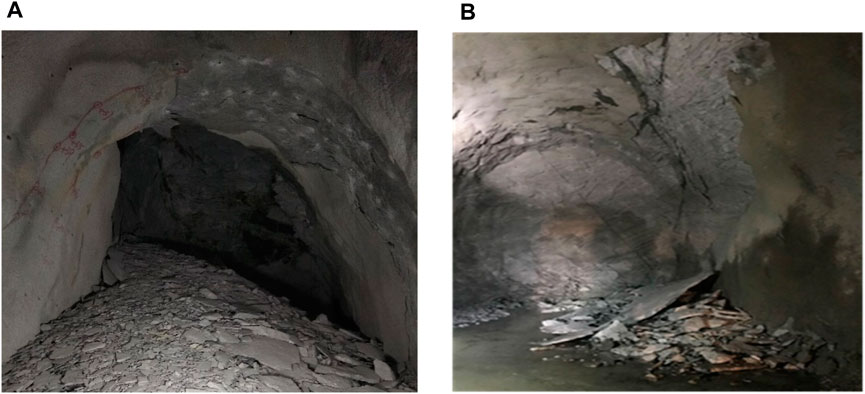
Figure 1. Instable problems in different tunnels. (A) is a stress-induced instability with low degree of jointing; and (B) is a structure-induced instability with high degree of jointing.
It can be concluded that when appraising the rock mass quality in a deep-buried hard rock tunnel with a high tendency of rockburst, the RMR system may work well in a fractured surrounding rock mass where structure-induced instability may occur. However, for a sparsely fractured surrounding rock mass in a high ground stress condition, the ap-plication of RMR may yield an overestimated result following the conventional approach because stress-induced failure happens time to time. Currently, some researchers have conducted studies to enhance the applicability of the RMR system for deep-buried hard rock tunnels by using factors such as rock mass damage risk degree (Xie et al., 2007) and the ratio of intact rock uniaxial compressive strength to maximum principal stress (Liu et al., 2010). Nevertheless, large-scale in situ tests are time-consuming and costly, and the modified input parame-ters are not very scientific. Consequently, these existing improved RMR systems for deep-buried hard rock tunnels are still limited.
Additionally, the ratio of intact rock uniaxial compressive strength to maximum principal stress and the rockburst intensity tendency index produced by MS monitoring can considerably reflect the qualities and stabilities of surrounding rock masses in deep-buried hard rock tunnels. However, they are only suitable for tunnels with a low de-gree of jointing and potential for stress-induced instability, but not very sufficient for structurally-controlled unstable tunnels.
In a word, the single use of RMR or the rockburst intensity tendency index is limited for assessing the rock mass quality of a deep-buried hard rock tunnel. To make the rock mass quality system more applicable, failure features in high ground stress conditions should be fully considered.
3 Improving the engineering rock mass quality classification system in deep-buried hard rock tunnels
3.1 Factors affecting engineering rock mass qualities at deep level
The engineering rock mass quality at deep levels can be divided into two parts: 1) basic rock mass quality (e.g., intact rock uniaxial compressive strength, degree of jointing, and ground stress); and 2) engineering factors (e.g., tunnel shape and the angle between tunnel axis and critical joint set). Especially in deep-buried hard rock tunnels, the influ-ence of high ground stress should not be neglected.
3.1.1 Rock mass strength
Strength is the basis of rock mass quality. A higher rock mass strength always indi-cates better quality and stability, and vice versa. Many parameters can be used to represent the rock mass strength, and the uniaxial compressive strength of intact saturated rock is widely used, which can be quickly measured. Additionally, this parameter can reflect the mechanical properties of a given rock block that has been softened by water and has good relationships with other mechanical parameters of the rock mass.
3.1.2 Rock joints
Rock mass structure is a critically controlled factor of rock mass failure and rock mass mechanical behavior. Rock joints are the basic elements of rock mass structure and their orientation, density, infilling material and intersected pattern, etc., have great influ-ences on rock mass quality and stability. Therefore, engineering rock mass qualities are also affected by rock joints
3.1.3 Groundwater condition
Groundwater often leads to a great volume of rock engineering instabilities, which not only mitigate the rock mass strength but also lubricate the joint walls, causing the en-gineering rock mass quality to become poorer.
3.1.4 Ground stress
Ground stress can be divided into (i) gravity stress; and (ii) tectonic stress, and they naturally exist in the crust. This kind of stress fundamentally results in deformations and failures of underground tunnels and is a premise of engineering rock mass quality classi-fication (Song and Jia, 2004). In high ground stress conditions, substantial strain energies accumulate. During the excavation process, these energies may be suddenly released, inducing rock mass failures and even rockburst events with various degrees.
3.1.5 Engineering factors
In deep rock engineering, some factors, including tunnel alignment, tunnel layout, tunnel scale, excavation method, and advance rate, have significant implications on engineering rock mass quality and should be considered.
3.2 Improvement thought of classification systems
Substantial strain energies are stored in deep hard rock masses, and after excavation, these energies may be suddenly released, resulting in large-scale brittle failure and dy-namic instability. Therefore, rockburst is a major factor affecting the engineering rock mass quality. Even if no rockburst events occur, failures and damages of varying degrees will be produced due to the high ground stress. The surrounding rock masses with differ-ent degrees of damage have various qualities, and after excavation, disturbed and retarded instabilities may be encountered.
There are differences between the failure modes of rock masses with various qualities, which can be characterized from the perspective of MS events, as shown in Figure 2.
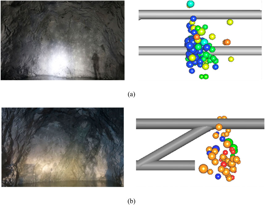
Figure 2. MS events occurring in rock masses of different jointing degree. (the rock mass quality ratings in this Figure are determined by P-wave velocity): (A) Rock mass quality rating Ⅰ with the P-wave velocity is 6500 m/s, the number of MS events are 167, the cumulative MS energy is 3.24 lgE/J; (B) Rock mass quality rating Ⅲ with the P-wave velocity is 5300 m/s, the number of MS events are 52, the cumulative MS energy is 2.59 lgE/J.
When the degree of jointing is lower, stress-induced failures are significant, and MS events are frequent. When the degree is higher, stress-induced failures are rare, and the MS events are inactive. Therefore, the damage degrees of rock masses and rockburst intensity tendency can be estimated by MS events after excavation.
Based on the MS monitoring approach, the characteristic parameters of MS events produced by rock mass cracking (after excavation) should be analyzed, and a comprehensive quantification index of rockburst intensity tendency should be developed and then incorporated into engineering rock mass quality classification. This may be beneficial in accurately assessing the engineering rock mass qualities of deep-buried hard rock tunnels. Additionally, during excavation process, the penetration method, tunnel advancement per cycle and field condition, etc., can be reflected by MS events, e.g., with the increase in tun-nel advancement per cycle, the MS energies are released more and more, and the frequen-cy of rockburst events tents to be increased (Yu, 2017). Therefore, the rockburst intensity tendency index that is based on MS monitoring can jointly capture the implications of ground stress and engineering factors on engineering rock mass qualities.
In short, the existing rock mass quality systems are limited for deep-buried hard rock tunnels. The authors believe that the relation between the rockburst intensity tendency index and high stress-induced failure characteristics can be utilized. Based on the RMR sys-tem, the rockburst intensity tendency index, which enables a full reflection of high stress-induced failure characteristics, can be incorporated into the classification system. In doing so, a new rock mass quality rating system for deep-buried hard rock tunnels (DHRT-RMR) was developed.
3.3 Rockburst intensity tendency index
3.3.1 Some commonly-used characteristic parameters of MS events
Based on in situ MS monitoring, some commonly used characteristic parameters can be used to quantify the rockburst intensity tendency index. These parameters include the cumulative number of MS events, cumulative MS released energy, cumulative MS apparent volume, MS event rate, MS released energy rate, and MS apparent volume rate.
3.3.2 Quantification of different levels of rockburst intensities
Based on the functional relation between different levels of rockburst intensities and various MS characteristic parameters (Feng et al., 2013), the rockburst intensity L can be calculated by
where A1 to A6 are the scores of cumulative numbers of MS events, cumulative MS released energy, cumulative MS apparent volume, MS event rate, MS released energy rate and MS apparent volume rate, respectively; and W1 to W6 are the associated weights, re-spectively, which can be determined referring to (Feng et al., 2015).
When determining A1 to A6, a standard rating table should be used (for more details see Section 5.2), in which the values of various MS parameters are scored in centesimal scale. The smaller the measured MS parameter values are, the lower the scores are, and the lower the rockburst intensity tendency ratings.
4 A new rock mass quality rating system for deep-buried hard rock tunnels (DHRT-RMR)
4.1 Development of the DHRT-RMR
Referring to the RMR system, multiple parameters were involved in developing the DHRT-RMR system. From the guidelines for selecting input parameters for rock mass classification systems (He et al., 2024), it can be concluded that all aspects influencing the engineering rock mass qualities should be covered, the weights of input parameters should be distinguished according to their importance, and the equivalent parameters should be avoided.
Therefore, considering the influencing factors presented in Section 3.1, five input parameters were selected,i.e., uniaxial compressive strength of intact saturated rock, Rock Quality Designation (RQD), joint condition, groundwater condition, and rockburst inten-sity tendency.
4.2 Weights of the five input parameters
To properly reflect the importance of the five input parameters of DHRT-RMR, the Analytic Hierarchy Process (AHP) was used to assign weights. Analytic Hierarchy Process (AHP) assigns weights by decomposing complex decision-making problems into different levels, constructing judgment matrices for pairwise comparison, calculating feature vectors, and ensuring consistency through consistency testing. The judgment matrix is as follows:
aij is the result of comparing the importance of element i and element j.
The AHP hierarchy model was established, as shown in Figure 3. In this section, the importance of some in-put parameters will be determined by their maximum rating values in the RMR system. By pairwise comparing these parameters, a judgment matrix will be constructed.
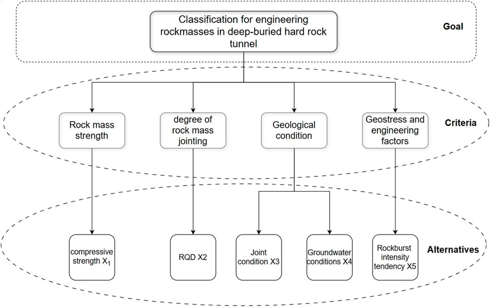
Figure 3. AHP hierarchy model.
The uniaxial compressive strength of intact saturated rock is considerably high in deep-buried hard rock tunnels with rockburst potential. Therefore, rock joints and the rockburst intensity tendency index are the major effective factors for tunnel rock mass qualities. In this context, referring to the RMR system, the importance degrees of uniaxial compressive strength of intact saturated rock (X1), RQD (X2), joint condition (X3), groundwater condition (X4), and rockburst intensity tendency (X5) are 15, 25, 20, 10, and 30 points, respectively.
Based on the judgment matrix (Table 1), the weights of all input parameters for DHRT-RMR were obtained. The largest eigenvalue (λmax) is 5, and the consistency index (CI) is 0. Consistency and random tests were conducted, and the consistency ratio (CR) is 0 (≤0.1), indicating satisfactory consistency. The weight vector of all input parameters, W = (w1, w2, w3, w4, w5), is (0.15, 0.25, 0.20, 0.10, 0.30), as shown in Table 1.
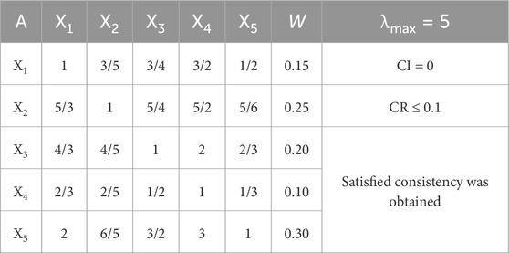
Table 1. Judging matrix and weight assignment.
4.3 Determination of scores
4.3.1 Scores of input parameters
The selected input parameters were graded, and the score of each input parameter is on a centesimal scale. The more favorable the input parameter value is to the tunnel rock mass quality, the higher the score, and vice versa.
Intact rock uniaxial compressive strength, RQD, and rockburst intensity tendency can be quantified, and based on Table 2, the corresponding scores can be obtained. However, the scores for joint condition and groundwater should be determined qualitatively (Table 2). Additionally, when assessing the joint condition, extra factors should be considered, such as the angle between the tunnel axis and the orientation of the critical joint set. If the joint orientations are unfavorable to tunnel stability, the score for joint condition should be reduced.
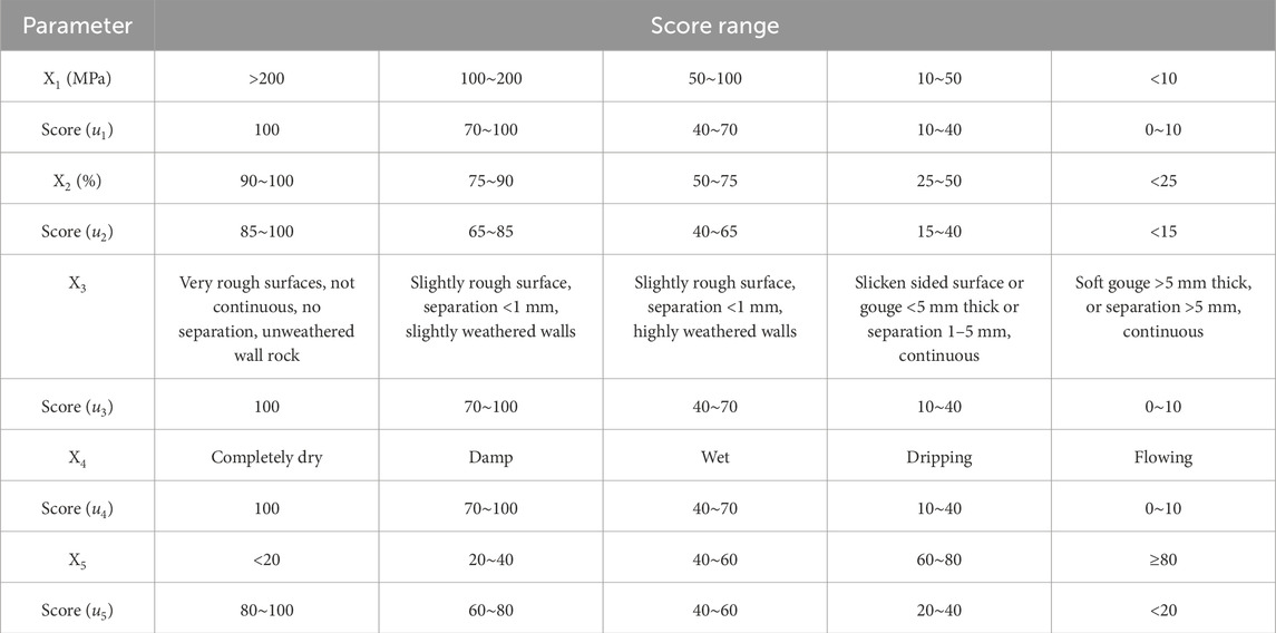
Table 2. Score range of DHRT-RMR system.
4.3.2 Final score of DHRT-RMR system
The final DHRT-RMR score can be determined based on Table 2. The score vector of all input parameters of DHR-RMR system U is (u1, u2, u3, u4, u5), and the weight vector W = (w1, w2, w3, w4, w5) is (0.15, 0.25, 0.20, 0.10, 0.30), and therefore, each input parameter’s score can be determined by fi = ui×wi, i = (1, 2, 3, 4, 5). (The final score of DHRT-RMR (F) is
4.4 Ratings of DHRT-RMR system
Referring to the RMR system and the tunnel support guideline based on rockburst ten-dency (Wang et al., 2016), the ratings of DHRT-RMR system were divided into five intervals, and the cor-responding classes is Ⅰ (Excellent), Ⅱ (Good), Ⅲ (Fair), Ⅳ (poor) and (Very poor). The degrees of jointing, stabilities and support schemes in the five classes were presented, respectively, in Figure 4.
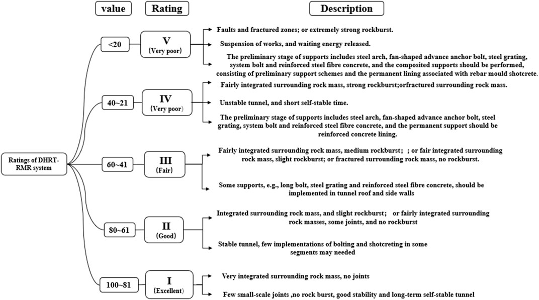
Figure 4. Ratings of DHRT-RMR system.
The DHRT-RMR system is slightly different from the conventional classification method, as it not only considers the basic rock mass quality but also takes into account the influences of rockburst and engineering factors on engineering rock mass qualities. In the same class rock masses, several cases may exist, e.g., when the rock mass is integrated but mild rockburst events occur, the rock mass is in Class Ⅱ, and however, when the rock mass is sparsely fractured but no rockburst event occurs, the rock mass is also in Class Ⅱ.
5 Applications to real cases
5.1 Description of the study area
A section of the railway in southwest China. The majority of these tunnels are deeply positioned, with depths exceeding a kilometer, and the deepest tunnel descends to 2080 m. Approximately 94 percent of segments in a tunnel (one of the forty-seven tunnels) have frequently experienced rockburst incidents. The lithologies predominantly consist of biotite granite intercalated with diorite, which are ashen, hard, and brittle, with an average uniaxial compressive strength of 160 MPa and an average uniaxial tensile strength of 7.6 MPa. Mechanical and unloading joints are well developed in the tunnel due to regional tectonic activity and surficial alteration features. The groundwater condition mainly consists of Quaternary pore water and fracture water, with the aquifer properties being very good. Two rows with a total of eight MS sensors were installed at the rear of the tunnel face. The eight sensors were divided into two groups, with each group comprising four sensors. The first group of sensors was placed 60 m–70 m from the tunnel surface, numbered D2-1 to D2-4, while the second group was placed 100 m from the tunnel surface, numbered D1-1 to D1-4. The boreholes for MS monitoring have a mean diameter of 75 mm, and the spatial arrangement of the sensors is shown in Figure 5.
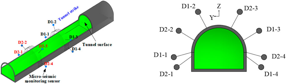
Figure 5. MS monitoring scheme in a tunnel.
5.2 Quantification of the rockburst intensity index of a tunnel
A case database of rockburst events in a tunnel was established, and the histogram is presented in Figure 6. Based on Figure 6, different degrees of rockburst events were classified according to various associated characteristic parameters, as shown in Table 3. It should be noted that because no extremely intense rockburst events occurred, and only a intense rockburst occurred in the monitoring segments, the characteristic parameters corresponding to strong and extremely strong categories were obtained through fitting analyses. Reviewing Table 3 reveals that the characteristic parameter values increase with the increase in rockburst degrees, which is therefore practical.
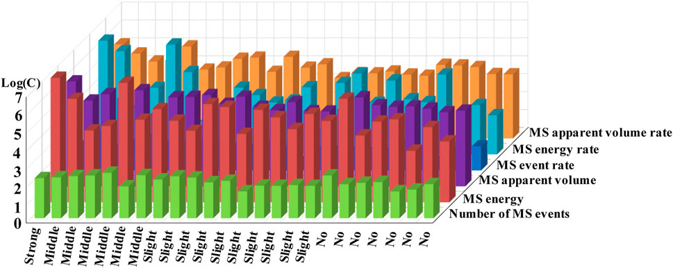
Figure 6. Rockburst events and its characteristic parameter values.
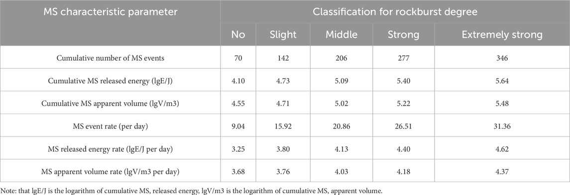
Table 3. Classification for rockburst degree based on MS characteristic parameters.
All the characteristic parameters in Table 3 were scored on a centesimal scale, and standard ratings to determine these scores are presented in Table 4. In this table, the values and scores of all the characteristic parameters were divided into five intervals, with higher ratings indicating higher characteristic parameter values.
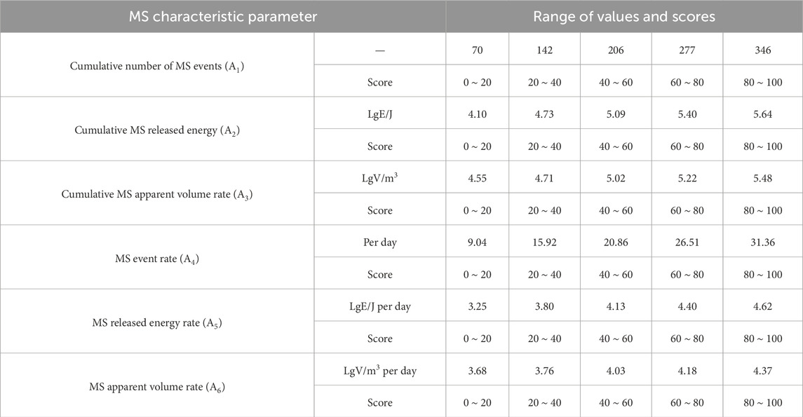
Table 4. Standard ratings to determine the scores of all input parameters of DHRT-RMR.
Based on Table 4, Equations (2) and (3), the weights of all the characteristic parameters in this tunnel W = {W1, W2, W3, W4, W5, W6} were determined by particle swarm optimization, which is {0.258, 0.321, 0.203, 0.067, 0.030, 0.121}. Therefore, the rockburst intensity L of a tunnel can be calculated by L = 0.258A1 + 0.321A2 + 0.203A3 + 0.067A4 + 0.030A5 + 0.121A6.
5.3 Engineering rock mass classification in the segment of the parallel adit from 195+280 to 195+300
5.3.1 Geological condition
The surrounding rock masses in the segments of the parallel adit from 195+280 to 195+300 consist mainly of gray and atrovirens granite. These rock masses are intact, with massive blocks that are unweathered and have high strength. After excavation, a set of joints is exposed on the south side: the dip direction/dip angle is 70°/70°, with a spacing of 0.7 m and no separations or infillings. On the north side of the tunnel surroundings, an-other set of joints is developed, with a dip direction/dip angle of 283°/85°, a spacing of 1 m, and a trace length of around 1.5 m, also without separations or infillings. In the middle of the south surrounding rock masses, uplifted joints occur, and the surface layers of rock masses in some regions are thin. The groundwater condition is damp or wet.
Based on the joint mapping, a 20 m × 20 m × 20 m joint network model was created along the tunnel axis, as shown in Figure 7. The RQD value is 92%, which was deter-mined by setting scanlines within this model (Xu et al., 2012).
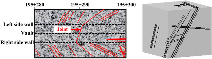
Figure 7. Joint trace map and joint network model in the segment of the parallel adit from 195+280 to 195+300.
5.3.2 Activity law of MS events
After tunnel formation, a total of 97 MS events were recorded until September 14th. The logarithm of cumulative MS release energy is 3.54 logE/J, and the logarithm of cumu-lative MS apparent volume is 4.34 log V/m3. The incubation time of MS events is 4 days, with an MS event rate of 24 per day. The MS energy release rate is 2.94 lgE/J per day, and the cumulative MS apparent volume rate is 4 lgV/m3 per day. The spatial and temporal dis-tribution of MS events is depicted in Figure 8. Based on Table 4 and Figure 8, the characteristic parameters of microseismic activity were scored to obtain {A1, A2, A3, A4, A5, A6} = {25, 15, 19, 75, 18, 58}. The rockburst intensity tendency L is calculated as 27.71 using Equation 1.
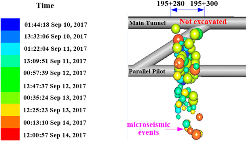
Figure 8. Spatial and temporal distribution of MS events in the segment of the parallel adit from 195+280 to 195+300.
5.3.3 Engineering rock mass classification results
5.3.3.1 DHRT-RMR classification
Based on the geological investigation data and the activity pattern of MS events, the scores of the input parameters for this study segment are 75, 86, 55, 70, and 63, respective-ly. Therefore, the final DHRT-RMR value (F) is 69.65, placing it in Class Ⅱ.
5.3.3.2 RMR classification
In the RMR system, the five input parameters are: 1) uniaxial compressive strength of intact rock; 2) RQD; 3) joint spacing; 4) joint condition; and 5) groundwater condition. RMR classification was performed, showing that the scores of the five parameters are 12, 18, 15, 28, and 13, respectively. The RMR value is calculated to be 86. Considering the im-plication of the orientation of critical joint sets, the adjustment score is −7. Therefore, the final RMR value is 79, which falls into Class Ⅱ.
5.3.4 Actual stability in the field
At 8 p.m. on September 14th, 2018, the mucking operation was completed. Cracks suddenly appeared on the concrete lining 15–20 m from the tunnel surface, caused by a slight rockburst. Immediate danger removal measures were taken, and many large rocks were scraped off. During this process, constant sounds could be heard, and rock blocks continuously fell, leading to slight rockburst occurrences. Fortunately, no blocks were fiercely ejected. Eventually, a hole about 1.5 m deep formed in the left-side wall, as shown in Figure 9. Meanwhile, water seeped down the hole.
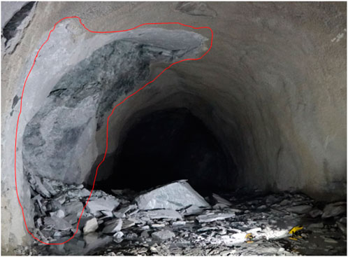
Figure 9. A hole about 1.5 m deep formed in the segment of the parallel adit from 195+280 to 195+300.
Influenced by this slight rockburst event, some well-defined joints appeared, but no large-scale instabilities occurred. It has been concluded above that the surrounding rock masses are in Class Ⅱ using both DHRT-RMR and RMR, which is in line with the prac-tice. However, relying solely on MS characteristic parameters implies that no rockburst will occur and the rock mass stability is excellent, which cannot accurately reflect the en-gineering rock mass qualities.
5.4 Engineering rock mass classification in the segment of the main tunnel from 195+280 to 195+300
5.4.1 Geological condition
The surrounding rock masses consist of gray, integrated, and unweathered granite, exhibiting high strength. Two large-scale joints were observed, characterized by high per-sistence, with dip directions/dip angles of 110°/90° and 120°/45°, respectively, and they lack separations and infillings. The joint walls appear smooth, and the two joints are conjugate. Groundwater conditions are dry.
A rock mass joint network model was constructed along the tunnel axis, as shown in Figure 10, and the measured RQD value is 100%.
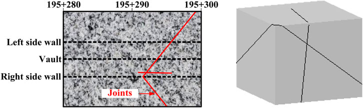
Figure 10. Joint trace map and joint network model in the segment of the main tunnel from 195+280 to 195+300.
5.4.2 Activity law of MS events
As the tunnel surface advanced, MS events occurred constantly and intensively. On October 7th, the number of MS events sharply increased, as shown in Figure 11. Therefore, the cumulative MS events up until October 8th were selected to analyze the activity pattern of MS events.
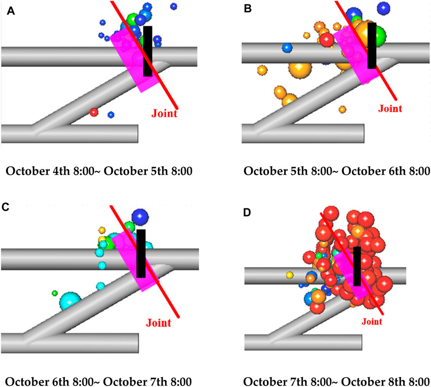
Figure 11. Distribution law of MS events along the segment of the main tunnel from 195+280 to 195+300 with the advancement of tunnel surface. (A) October 4th 8:00∼ October 5th 8:00 (B) October 5th 8:00∼ October 6th 8:00 (C) October 6th 8:00∼ October 7th 8:00 (D) October 7th 8:00∼ October 8th 8:00.
Until October 8th, the cumulative number of MS events reached 234, with the loga-rithm of cumulative MS released energy at 5.56 lgE/J, and the logarithm of cumulative MS apparent volume at 5.31 lgV/m3. The incubation time of MS events was 24 days, resulting in an MS event rate of 9 per day, an MS energy release rate of 4.16 lgE/J per day, and an MS apparent volume rate of 4 lgV/m3 per day. The spatial and temporal distribution of MS events is depicted in Figure 12. Based on Table 4; Figure 11, the characteristic parameters of microseismic activity were scored to obtain {A1, A2, A3, A4, A5, A6} = {75, 90, 88, 20, 65, 58}. The rockburst intensity tendency index L was calculated to be 76.41.
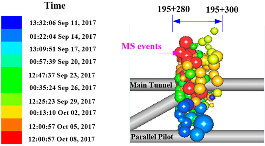
Figure 12. Spatial and temporal distribution of MS events in the segment of the main tunnel from 195+280 to 195+300.
5.4.3 Engineering rock mass quality classification results
Based on Figure 12 and the geological investigation, the scores of all input parame-ters of the DHRT-RMR system are 75, 92, 50, 80, and 21, respectively. Consequently, the final DHRT-RMR score (F) is 58.55, which belongs to Class Ⅲ.
The RMR system was applied, and the scores of all RMR input parameters are 13, 20, 17, 28, and 13, respectively. Consequently, the RMR score is 91. Taking into account the orientation of the critical joint set, the adjustment score is −10. Therefore, the final RMR value is 81, which is in Class Ⅰ.
5.4.4 Actual stability in the field
On 8 October 2018, after the mucking had been completed, a large-scale struc-ture-induced rockburst occurred at the junction between the segment of the main tunnel from 195+295 to 195+296 and the 11# crosscut gallery. Subsequently, numerous massive blocks were dislodged, accompanied by constant sounds and block falls. Ultimately, a hole approximately 15 m long, 1.5 m wide, and 0.6 m deep was formed, as depicted in Figure 13.
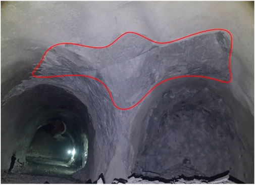
Figure 13. A rockburst occurred in the junction between the segment of main tunnel from 195+295 to 195+296 and the 11# crosscut galley.
The collapse induced by this rockburst occurred in the segment of the main tunnel from 195+280 to 195+300, resulting in the true surrounding rock mass quality being categorized as Class Ⅲ. The calculated rockburst intensity tendency index L is 76.41, indicating a potential for medium rockburst. However, the RMR suggests a rock mass quality in Class Ⅰ. Hence, the DHRT-RMR system is more accurate than the RMR system in this circumstance.
5.5 Engineering rock mass classification in the segment of the exit main tunnel from 199+655 to 605
5.5.1 Geological condition
The cracking area is located in the surrounding rock on the north side of the tunnel face, about 65 m away from the tunnel plane, with shallow pits of rock spalling: Depth d<0.3 m, coverage area about 1 m2, quiet shooting process, no drop. The surrounding rock in the area is granite, grayish white, blocky. The regional cracks extend around the shallow pit, and three groups of cracks are clearly visible. One group of cracks has a dip angle of 30°, a tendency of 220°, a crack width of about 0.5 cm, no filling, no weathering, a spacing of about 0.2 m, and an extension of about 1 m. They are distributed on the left side of the shallow pit; one group of cracks has a dip angle of 15°, a tendency of 110°, a crack width of about 0.3 cm, no filling, no weathering, a spacing of about 0.5 m, and an extension of about 2 m. They are distributed on the right side of the shallow pit; one group of cracks has a dip angle of 75°, a tendency of 230°, a maximum crack width of about 1.5 cm, no filling, no weathering, a spacing of about 0.3 m, and an extension of about 1.5 m. They are distributed in the upper right part of the shallow pit. The entire cracking area covers an area of about 10 m2. The nearby rock mass is dry, the structure is relatively complete, and the joints are well developed. It is currently in a relatively stable state, and the site has been marked as a rock burst cracking warning.
A rock mass joint network model was constructed along the tunnel axis, as shown in Figure 14, and the measured RQD value is 80%.
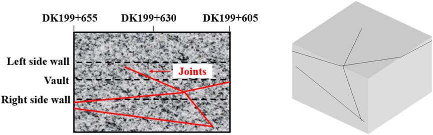
Figure 14. Joint trace map and joint network model in the segment of the main tunnel from DK199+655 to 605.
5.5.2 Activity law of MS events
The microseismic monitoring data of the excavation section of the exit main tunnel “DK199+655∼605″were subjected to noise filtering and positioning analysis, and 11 effective microseismic events were found, and no microseismic events occurred at the pile number DK199+625 during the current excavation disturbance stage. Figure 15 is the temporal and spatial distribution of microseismic events in this excavation section. Each sphere represents a microseismic event, and the color of the sphere represents the time of the event. The size of the sphere represents the local magnitude of the event. The larger the size, the greater the magnitude. It can be seen that:
(1) The number of events in this excavation area is relatively small and the distribution is relatively discrete, with most of them being small energy events;
(2) At present, there are no effective microseismic events in this area (the sensor is only 10 m away from the cracking area), indicating that no further fractures have occurred in this area at this stage. The occurrence of initial cracking and block falling is mainly affected by the geological conditions of the surrounding rock in this area.
(3) Based on the existing information on the characteristics of microseismic activity, the potential risk of time-lagged rockburst in this area is low, but local collapse and block falling due to block sliding cannot be ruled out.
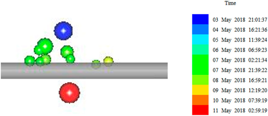
Figure 15. Spatial and temporal distribution of MS events in the segment of the exit main tunnel from DK199+ 655 to 605.
Based on the microseismic activity law of the exit tunnel DK199+655∼605 section after excavation, the characteristic parameters of microseismic activity were scored using Table 4; Figure 15, the result was {A1, A2, A3, A4, A5, A6} = {15, 20,17,19, 3, 48}. The rockburst intensity tendency index L in this area is 20.08.
5.5.3 Engineering rock mass classification results
Based on the geological conditions and microseismic activity patterns of the DK199+655∼605 section of the import main tunnel, the engineering quality grading index scores for this section are determined to be 75, 69, 80, 95, and 80. The total engineering quality grading score of the tunnel is F = 78, which is a Class II surrounding rock tunnel.
The traditional RMR classification method is used to classify the engineering quality of the imported tunnel DK199+655∼605 section. The scoring values of each indicator are 12, 17, 17, 28, and 15, and the scoring value F = 89. Since the structural surface is not conducive to the stability of the tunnel, the correction value B is −10. Therefore, the total engineering quality score of the imported tunnel DK199+655∼605 section is 79 points, which belongs to the Class II surrounding rock tunnel.
5.5.4 Actual stability in the field
After the slag was discharged on 27 May 2018, many unloading cracks appeared in the surrounding rock near the exit main tunnel “DK199+625”after excavation and unloading under high stress environment. The unloading cracks and primary cracks cut each other, forming a certain scale of rock blocks in the surrounding rock on the north side. After the initial support spraying, on the one hand, it hindered the block from sliding toward the free surface, and on the other hand, it enhanced the cohesion of the structural surface, making it difficult for the block to slide toward the free surface, thus enhancing the stability of the tunnel. However, affected by the disturbance of multiple excavation and unloading of the front face, the plate-like block gradually slid toward the free surface, resulting in the cracking and spalling of the initial support in local areas, as shown in Figure 16.
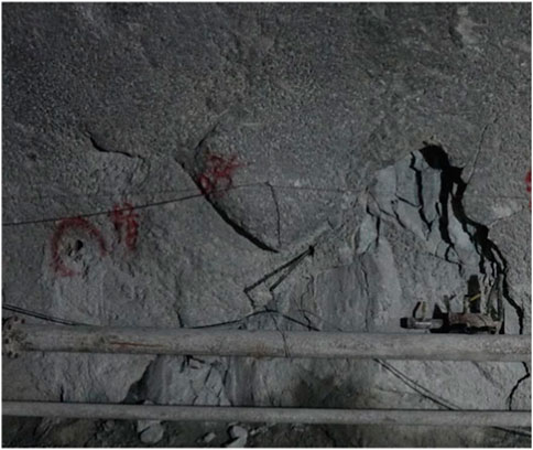
Figure 16. Cracking area of the DK199+655∼605 section of the entrance tunnel.
The DK199+655∼605 section of the entrance tunnel cracked. Affected by the excavation disturbance, the original shotcrete support showed cracks and falling blocks. Between May 27 and May 29, the project team conducted 7 public surveys in the area and found no cracks, further expansion, or rock falling. The grading results of the high-stress hard rock tunnel engineering quality grading method and the traditional RMR grading method are consistent with the actual engineering practice.
As stated in Sections 5.3, 5.4 and 5.5, the single use of RMR or rockburst intensity ten-dency is limited for deep-buried hard rock tunnels. The developed DHRT-RMR system can accurately assess the rock mass qualities in such tunnels. For deeply buried hard rock tunnels, even rock masses with good integrity can experience a significant amount of rock fracturing due to high stress, leading to rock instability disasters such as rock bursts, rock explosions, and stress-induced collapses. However, traditional rock mass stability classification methods, such as the RMR method, are unable to accurately assess the stability of such rock masses. Therefore, the classification of stability for deeply buried hard rock tunnels not only needs to consider the indicators of traditional grading methods, but also needs to consider the rock fracturing that occurs due to energy release after excavation. The test results from the three different working conditions also confirm this viewpoint. This is also the reason why this study combines the RMR classification method with the rock burst strength index to establish the DHRT-RMR classification method. The test results also demonstrate that DHRT-RMR can more accurately assess the stability of tunnel surrounding rock under different conditions, showing excellent performance.
6 Conclusion
The discussion of the drawbacks of conventional rock mass quality classification systems indicates that the sole use of the RMR system and rockburst intensity tendency is limited for evaluate the surrounding rock quality of deep buried hard rock tunnels.
An engineering rock mass quality classification system for deep-buried hard rock tunnels (DHRT-RMR) was developed. The rockburst intensity tendency was quantified based on in-situ microseismic monitoring. The input parameters of DHRT-RMR were selected, their weights were defined, and the standard ratings to determine a final DHRT-RMR score were established. The input parameters for the DHRT-RMR were selected, their weights were defined, and the standard ratings to determine a final DHRT-RMR score were established.
The DHRT-RMR, RMR, and rockburst intensity tendency index were applied to a tunnel. The classification results demonstrate that the sole use of the RMR system and rockburst intensity tendency cannot fully reflect the true rock mass qualities of real cases. However, the developed DHRT-RMR system performs distinctly well in this aspect.
Data availability statement
The original contributions presented in the study are included in the article/supplementary material, further inquiries can be directed to the corresponding authors.
Author contributions
ZW: Conceptualization, Investigation, Writing–original draft. LW: Methodology, Data curation, Writing–review and editing. TL: Formal Analysis, Software, Supervision, Writing–review and editing. W-JN: Supervision, Validation, Visualization, Project administration, Resources, Writing–review and editing.
Funding
The author(s) declare that no financial support was received for the research, authorship, and/or publication of this article.
Conflict of interest
The author(s) declare financial support was received for the research, authorship, and/or publication of this article. This research was funded by the Project of Youth innovation Promotion Association of Chinese Academy of Sciences (No. 2021326).
Publisher’s note
All claims expressed in this article are solely those of the authors and do not necessarily represent those of their affiliated organizations, or those of the publisher, the editors and the reviewers. Any product that may be evaluated in this article, or claim that may be made by its manufacturer, is not guaranteed or endorsed by the publisher.
References
Arild, P. (1996). Characterizing rock masses by the RMi for use in practical rock engineering: Part 1: the development of the Rock Mass index (RMi). Tunn. and Undergr. Space Technol. 11 (2), 175–188.
Chen, L., Ge, Y. F., Zeng, X. M., Wang, H. Y., Li, C. D., Dong, S., et al. (2023). Rapid evaluation of rock mass integrity of engineering slopes using three-dimensional laser scanning. J. Earth Sci. 34 (6), 1920–1925. doi:10.1007/s12583-023-2007-z
Deere, D. U., Hendron, A. J., and Patton, F. D. (1966). Design of surface and near-surface construction in rock. ARMA US Rock Mechanics/Geomechanics Symposium. ARMA-66-0237.
Dong, J., Chen, Q., Yuan, G., and Xie, K. (2024). Rock mass structure classification of caves based on the 3D rock block index. Appl. SCIENCES-BASEL 14, 1230. doi:10.3390/app14031230
Feng, G. L., Feng, X. T., Chen, B. R., Xiao, Y. X., and Yu, Y. (2015). A microseismic method for dynamic warning of rockburst devel-opment processes in tunnels. Rock Mech. Rock Eng. 48 (5), 2061–2076. doi:10.1007/s00603-014-0689-3
Feng, X. T., Chen, B. R., Zhang, C. Q., Li, S., and Wu, S. (2013). Mechanism,Warning and dynamic control of rockburst devel-opment processes (in Chinese). Beijing: Science Press, 305–421.
Goel, R. K., Jethwa, J. L., and Paithankar, A. G. (1995). Indian experiences with Q and RMR systems. Tunneling Undergr. Space Technol. 10 (1), 97–109. doi:10.1016/0886-7798(94)00069-w
Han, Z., Li, D., and Li, X. (2022). Effects of axial preforce and loading rate on Mode I fracture behavior of granite. Int. J. Rock Mech. Min. Sci. 157, 105172.
Han, Z., Li, D., Wang, H., and Zhao, J. (2023). Initiation and propagation of a single internal 3D crack in brittle material under dynamic loads. Eng. Fract. Mech. 285, 109299. doi:10.1016/j.engfracmech.2023.109299
He, F. L., He, F. L., and He, F. L. (2024). Review and prospect of rock classification in tunnel engineering (in Chinese). Mod. Tunn. Technol. 61 (2), 60–66.
He, M. C., Xie, H. P., Peng, S. P., and Jiang, Y. (2005). Study on rock mechanics in deep mining engineering. Chin. J. Rock Mech. Eng. (16), 2803–2813. (in Chinese).
Jaiswal, A., Verma, A. K., and Singh, T. N. (2024). A critical review of rock mass classification systems for assessing the stability condition of rock slopes. Environ. EARTH Sci. 83, 245. doi:10.1007/s12665-024-11532-2
Ko, J., and Jeong, S. (2017). A study on rock mass classifications and tunnel support systems in unconsolidated sedimentary rock. Sustainability 9, 573. doi:10.3390/su9040573
Liu, Y. K., Cao, P., Yi, Y. L., Zhang, X. Y., and Chen, R. (2010). Revised RMR system on underground deep engineering rock mass property (in Chinese). J. Central South Univ. Sci. Technol. 41 (4), 1497–1505.
Liu, Z. X., and Dang, W. G. (2014). Rock quality classification and stability evaluation of undersea deposit based on M-IRMR. Tunn. Undergr. Space Technol. 40, 95–101. doi:10.1016/j.tust.2013.09.013
Mohammad, H., and Razie, S. K. (2013). Seismic analysis of the rock mass classification in the Q-system. Int. J. Rock Mech. and Min. Sci. 62, 123–130. doi:10.1016/j.ijrmms.2013.05.003
Narimani, S., Davarpanah, S. M., Bar, N., Torok, A., and Vasarhelyi, B. (2023). Geological strength index rela-tionships with the Q-system and Q-slope. Sustainability 15, 11233. doi:10.3390/su151411233
Niu, G., He, X., Xu, H., and Dai, S. (2024). Development of rock classification systems: a comprehensive review with emphasis on artificial intelligence techniques. ENG 5 (1), 217–245. doi:10.3390/eng5010012
Niu, W. l., and Li, T. B. (2015). Optimization of BQ method used in rock quality evaluation of rockburst tunnel(in Chinese). J. Chengdu Univ. Technol. 42 (6), 658–664.
Qian, Q., Zhou, X., and Xia, E. (2012). Effects of the axial in situ stresses on the zonal disintegration phenomenon in the surrounding rock masses around a deep circular tunnel. J. Min. Sci. 48 (2), 276–285. doi:10.1134/s1062739148020086
Romana, M. (1993). A geomechanical classification for slopes: slope mass rating. Compr. Rock Eng. 3 (1), 575–599.
She, S., and Lin, P. (2014). Some developments and challenging issues in rock engineering field in China(in Chinese). Chin. J. Rock Mech. Eng. 33 (3), 434–457.
Somodi, G., Bar, N., Kovács, L., Arrieta, M., Török, A., and Vásárhelyi, B. (2021). Study of rock mass rating (RMR) and geological strength index (GSI) correlations in granite, siltstone, sandstone and quartzite rock masses. Appl. Sciences-Basel 11, 3351. doi:10.3390/app11083351
Song, C., Zhao, T., and Xu, L. (2024). Probabilistic classification of surrounding rock mass of tunnels based on fully Bayesian Gaussian process classification (fB-GPC) with consideration of influencing factors selection. Geol. J. doi:10.1002/gj.4925
Song, Y., and Jia, G. C. (2004). Key engineering geological problem and investigation for deeply embedded tunnel (in Chinese). J. Eng. Geol. 2004, 5.
Terzaghi, K. (1946). “Rock defects and loads in tunnel supports,” in Rock tunneling with steel supports. The commercial shearing and stamping Co. Editors R. V. Proctor, and T. L. White (Youngstown, Ohio), 47–83.
Wang, L. H., Li, J. R., Li, J. L., Wang, K., Xu, X., et al. (2013). Correction of RMR system and its engineering application (in Chinese). Chin. J. Rock Mech. Eng. 32 (S2), 3309–3316.
Wang, Q. W., Ju, N. P., Du, L. L., et al. (2016). Research on rockburst prediction and engineering measures of long and deep-lying tunnels (in Chinese). Hydrogeology Eng. Geol. 43 (6), 88–94.
Wickham, G. E., Tiedemann, H. R., and Skinner, E. H. (1972). “Support determination based on geologic predictions,” in Proceedings North American rapid excavation tunneling conference. Editors K. S. Lane, and L. A. Garfield (Chicago, NY), 43–64.
Xie, B. X., Chen, Y. J., and Shi, X. Z. (2007). IRMR method for evaluation of surrounding rock quality in deep rock mass engineering (in Chinese). J. Cent. South Univ. Sci. Technol. 38 (5), 987–992.
Xie, H. P. (2017). Research framework and anticipated results of deep rock mechanics and mining theory (in Chinese). Adv. Eng. Sci. 49 (2), 1–16.
Xu, W., Hu, X. L., Huang, L., Zou, Z., and Ni, W. (2012). Research on RQD of rock mass calculated by three-dimensional discontinuity network simulation method and its accuracy comparison (in Chinese). Chin. J. Rock Mech. Eng. 31 (04), 822–833.
Xu, H., Zhang, Z., Zhang, Y., Jiang, Q., Qiu, S., Zhou, Y., et al. (2024). Effects of natural stiff discontinuities on the deformation and failure mechanisms of deep hard rock under true triaxial conditions. Eng. Fail. Anal. 158, 108034.
Xue, H. S., Song, Y. H., Feng, M., and Ju, G. H. (2024). New method to estimate rock mass deformation modulus based on BQ system. Appl. Sciences-Basel 14, 3736. doi:10.3390/app14093736
Yang, L., and Wei, J. (2023). Prediction of rockburst intensity grade based on SVM and adaptive boosting algorithm (in Chinese). Earth Sci. 48 (5), 2011–2023.
Yu, Y. (2017). Characteristics and evolution mechanism of micro-seismic events of rockbursts in deep rock tunnels (in Chinese). Hydro-Science Eng. 2017 (1), 26–31.
Keywords: deep-buried hard rock tunnel, rock mass quality classification, microseismic monitoring, rockburst intensity tendency index, DHRT-RMR system
Citation: Wu Z, Wu L, Lin T and Niu W-J (2024) An engineering rock mass quality classification system for deep-buried hard rock tunnels. Front. Earth Sci. 12:1453912. doi: 10.3389/feart.2024.1453912
Received: 24 June 2024; Accepted: 26 July 2024;
Published: 11 September 2024.
Edited by:
Li Ren, Sichuan University, ChinaCopyright © 2024 Wu, Wu, Lin and Niu. This is an open-access article distributed under the terms of the Creative Commons Attribution License (CC BY). The use, distribution or reproduction in other forums is permitted, provided the original author(s) and the copyright owner(s) are credited and that the original publication in this journal is cited, in accordance with accepted academic practice. No use, distribution or reproduction is permitted which does not comply with these terms.
*Correspondence: Longliang Wu, MjAxNzA1MzEwODE1QHNtYWlsLnh0dS5lZHUuY24=; Wen-Jing Niu, bml1d2pAZ3h1LmVkdS5jbg==