 Xianwei Zhao1,2
 Dengfeng Yang
- 1Engineering Laboratory of Deep Mine Rockburst Disaster Assessment, Jinan, China
- 2Geophysical prospecting and surveying team of Shandong Bureau of Coal Geology, Jinan, China
- 3School of Science, Qingdao University of Technology, Qingdao, China
The mining activation of hidden faults under dynamic and static loads is an important reason for the occurrence of floor water inrush disasters in deep coal seam mining. The formation and evolution mechanism of water inrush channel caused by mining on the floor of hidden faults were analyzed through numerical simulation, from the perspective of fracture mechanics, a model was constructed to explore the influence of combined dynamic and static loads on the propagation of water with cracks. A conclusion was drawn that the effects of mining stress and confined water have led to rapid expansion of hidden fault cracks and significant improvement in permeability, at the same time, the confined water in the hidden fault also has a scouring and expansion effect on the cracks, accelerating their development speed. There are spatial and temporal differences in the penetration patterns of hidden faults at different positions of floor, and the closer it is to the goaf, the more likely it is to experience activation of hidden faults and water inrush. When there are multiple hidden small faults in the floor, there is an alternating change between the water inrush growth area and the flow stable area with similar cyclic characteristics. The effect of dynamic load will increase the pore pressure in cracks, and increase the stress intensity factor at the crack tip, and more easily induce crack expansion and penetration failure. The critical water pressure calculation equation for crack propagation and failure under dynamic and static loads was derived, and the calculation method for the minimum safe thickness of the floor was further analyzed, the influence of water pressure, crack length, inclination angle, and mining depth on it was discussed. The effect of dynamic load will increase the pore pressure in cracks, and increase the stress intensity factor at the crack tip, and more easily induce crack expansion and penetration failure. Finally, the theoretical analysis results were verified by an engineering examples. The research results can provide theoretical basis for predicting and preventing water inrush from the mining floor, which is beneficial for the safe and sustainable mining of coal mines.
1 Introduction
Water inrush from floor is one of the main forms of mine water disaster in China, with the continuous increase of mining depth, the distance between the main mining coal seam and the lower Ordovician limestone aquifer is continuously reduced, the impact of mining stress on the stability of surrounding rock is more and more significant, and the high confined water in the floor aquifer has a prominent role in the progressive ascending and breaking of the floor. Especially when there are hidden faults in the floor, the location is more random, the range of distribution is larger, it is more likely to cause water inrush accidents from the mine floor under the combined action of strong mining and high water pressure (Wu, 2014; Xie et al., 2015; Kang et al., 2019). The water inrush raised by activation of hidden faults in the floor has become an important form of water inrush in deep mining.
Many scholars have already done much work on the mechanism of water inrush through fault and made a lot of scientific research achievements. Academician Peng Suping et al. (Peng et al., 2001) pointed out that the fault activation reduced the distance of periodic roof weighting, and the abutment pressure was lower when it passes the fault than when there was no fault; Gou et al. (Gou and Hu, 2006) pointed out that the deformation and failure of surrounding rocks of mining roadways was asymmetric in the horizontal and vertical directions of the area affected by the fault, and the damage was more serious when the floor was close to the fault; Huang et al. (Huang et al., 2010) pointed out that when the fault mining activation, the upper fracture opens first and the lower part closes, the footwall roof fully falls, and the “cantilever beam” failure feature appears in the hanging wall; Li et al. (Li et al., 2010) found that the fault was easier to be activated by mining when the working face advances along the footwall; Wang et al. (Wang et al., 2012) proposed three failure modes of the deep roof beam: layered delamination from the bottom to the top, integral fracture of normal fault or reverse fault, and integral fracture from the upper left corner; Academician Kang et al. (Jiang et al., 2013) proposed to strengthen the research on the mechanism of overlying rock fracture and the relationship between surrounding rock and support in high-strength mining sites, and to deeply analyze the precursor characteristic information of roof disasters; Jiang et al. (Shi and Hou, 2011) pointed out that fault activation and sliding caused dynamic loading on the roof, leading to large-scale instability of coal and rock masses; Shi et al. (Zhang and Liu, 2016) found that as the fracture angle of the fault increases, the failure modes of the fault were sequentially manifested as failure together with the overlying rock, shear failure, and tensile failure, and the larger the dip angle, the easier it was to activate. Zhang et al. (Lv et al., 2014) found that the magnitude of normal stress was positively correlated with the acute angle of fault strike, and the relationship between shear stress and acute angle of strike was determined by the ratio of maximum and minimum horizontal stresses; Lv et al. (Li et al., 2014) provided the reasons and mechanisms for the formation of rockburst; Li et al. (Cui and Yao, 2011) pointed out that the influence of fault dip angle on footwall mining was greater than that of hanging wall; Cui et al. (Xu et al., 2012) found that as the distance between the working face and the fault plane decreases, the degree of damage to the coal seam and roof rock mass increases; Xu et al. (Zhao, 2014) pointed out that the mining action causes the loss of balance between groundwater and geostress, leading to the fault activation and water inrush; Zhao et al. (Liu et al., 2017) found that the concealment and difficulty in exploring hidden small structures were the reasons why the water inrush accidents on the floor difficult to control. Liu et al. (Zhang and Pang, 2010) established a three-level warning model for mine water inrush. Zhang and Pang (Chen et al., 2011) established a water inrush model for the floor from the perspective of damage mechanics theory and derived the hazard coefficient of water inrush. Ma et al. (Ma et al., 2022a; Ma et al., 2022b) pointed out that with the progress of the three-phase flow, rock particles near the fluid outlet are first fluidized and constantly migrate outward, resulting in an increase of the porosity and permeability in fault rock.
Many scholars have conducted in-depth research on hidden faults. Chen et al. (Chen et al., 2007; Yang et al., 2015; Yang et al., 2016a) pointed out that when the branching cracks extend to an effective waterproof layer thickness that was insufficient to resist the effects of mining stress and confined water pressure, water inrush occurs in the floor. Li et al. (Li et al., 2009a) found that the development degree of small faults in the rock mass of the coal seam floor has an important impact on the lag time of water inrush. Chen (Chen et al., 2015) pointed out that small angle hidden faults were subjected to greater tensile and shear stresses, making them prone to forming serious damage areas, the degree of water inrush damage was also greater than that of large angle faults. Zhang et al. (Zhang et al., 2016; Zhang et al., 2018) pointed out that the delayed water inrush was not only related to the spatial relationship between hidden faults and coal seams and the pressure of confined water, but also to the degree of development of hidden faults and their spatial distance from coal seams. Wang et al. (Wang et al., 2018a; Wang and Yao, 2022) divided the progressive uplift process of hidden faults into four stages: natural uplift stage, progressive uplift stage, enhanced uplift stage, and breakthrough stage. Yuan et al. (Yuan et al., 2019) found that the water inrush channel generated micro cracks in the surrounding rock of the fault from bottom to top and micro cracks from top to bottom before and after passing through the fault in the working face. Wu et al. (Wu et al., 2004; Wu, 2014; Wu and Li, 2016) studied and analyzed the mechanism of floor mining induced water inrush under the influence of faults through on-site testing and numerical simulation methods. Hu et al. (Hu et al., 2014) pointed out that the water inrush from hidden faults was mainly related to the burial depth, friction angle, direction of working face advancement, and the pore water pressure. Zhao et al. (Zhao et al., 2019a) found that the local stress disturbance of hidden faults affected the extension direction of seepage paths. Gao et al. (Gao et al., 2020; Gao et al., 2022) pointed out that The effective flow intensity was independent of the fracture density and connection path length but had a negative correlation with the correlation length. Huang Hao and Wang (Huang and Wang, 2015) pointed out that the main factor affecting the progressive uplift failure of hidden faults was the initial height of fault development. Liu (Liu et al., 2020) classified the hidden fault in the coal seam floor into three types: high level fault, medium level fault, and low level fault; Sun et al. (Sun et al., 2017) analyzed and obtained the variation law between the mining extension length of normal and reverse hidden faults and the confined water pressure and lateral pressure coefficient of the floor; Li et al. (Li et al., 2022) pointed out that there was a significant change in the longitudinal stress of tunnel structures under hidden fault displacement. Zhang et al. (Zhang et al., 2015; Zhang et al., 2017; Guo W. J. et al., 2018) found that the spatial location and distribution pattern of hidden structures were the key to the occurrence of water inrush.
The above research results mainly focus on the analysis of damage mechanisms under static loads, while there is relatively little research on the problem of water inrush from hidden faults induced by dynamic disturbances. The dynamic loads such as roof collapse, rockburst, and mine tremors act on the rock layers of the floor, which on the one hand leads to the adjustment of the stress state of the floor fault zone, and on the other hand, directly affects the pore water pressure and friction strength of the rock mass within the fault zone. The increase of pore water pressure in the rock mass within a fault not only reduces the shear strength of the fault zone, but also reduces the effective normal stress. The decrease in friction strength on the fault surface will also reduce the shear strength of the fault, which will be beneficial for the occurrence of slip activation in the fault. Therefore, the process of water inrush from the deep mining floor occurs when the floor has already been subjected to high static load conditions and is disturbed by dynamic loads, which includes both static and dynamic problems.
Currently, fracture mechanics research methods are increasingly being used in the study of coal mine disasters (Chen et al., 2007; Li et al., 2009a; Li et al., 2009b; Li et al., 2011; Zhang et al., 2014; Yang et al., 2015; Yang et al., 2016a; Yang et al., 2016b; Gao et al., 2017; Wang et al., 2018b; Zhao et al., 2019b; Wang et al., 2020; Yang, 2021). In the process of deep coal seam mining, the floor with hidden faults is damaged and water inrush occurs under the action of mining induced stress. The activation, expansion, and connectivity of hidden faults within the floor promote the process of floor failure. Considering the arbitrary dip angle of hidden faults, it can be assumed that the floor rock layer is a rock beam with a central oblique crack, and the process of “crack activation extension penetration” under mining stress is the process of water inrush from the floor rock layer. Therefore, the method of analyzing the propagation of central crack damage in fracture mechanics can be combined to analyze the failure and water inrush formation process of the floor rock layer with hidden faults.
This article described the dynamic development process of hidden fault cracks under the coupling of mining induced stress and confined water through a numerical simulation system. The mechanical model of hidden fault water inrush under dynamic and static load disturbance was established based on fracture mechanics. A fracture mechanics analysis method for the mechanical mechanism of mining induced water inrush from the floor of hidden faults was provided, the static and dynamic stress triggering mechanisms of fault activation was explored, and the critical water pressure calculation formula for the tensile shear propagation mode of crack occurrence was obtained, and a reasonable calculation method for the minimum safe thickness of the bottom rock mass under excavation disturbance and water pressure has been derived, in order to provide theoretical and methodological basis for predicting, warning, and preventing water inrush disasters in the floor with hidden faults. The research results of the paper can effectively promote the safety production of mine.
2 Simulation analysis process of water inrush from floor with hidden faults
2.1 Model construction
Huipodi coal mine is located in the south of Fenxi County, northwest of Linfen, Shanxi Province. The average thickness of No.11 coal seam is 2.96 m, with a distance of 15.14–35.89 m from the Ordovician limestone, and an average of 25.4 m. The main aquifers affecting the mining of the No.11 coal seam in the research area are the K2 limestone aquifer of the Taiyuan Formation at the top and the Ordovician limestone aquifer group at the bottom. K2 limestone has an average thickness of 8.9 m, with moderate to weak water bearing capacity, mainly composed of static reserves, and is prone to drainage; The Ordovician limestone is a thick layer of limestone with strong water bearing capacity, and is the main aquifer that affects the safe mining of coal seams in this area. It is relatively close to the No.11 coal seam and is the key aquifer of this study.
We took the mining process of the coal with the risk of water inrush from floor in Huipodi Coal Mine, Xibeifen, Hongkong County, Shanxi Province as an example, the RFPA2D-Flow (Li et al., 2009a; Li et al., 2009b; Li et al., 2011) software was used to simulate the damage evolution process and water inrush characteristics of the floor rock mass with hidden faults during mining. The model consists of three irregular hidden small faults located at 100 m, 175 m, and 250 m on the left boundary of the model, all of which are water conducting faults. From the perspective of fluid-structure interaction, the whole process of hidden fault activation, fracture evolution and coalescence, and water inrush caused by the damage of floor aquifuge in the coal mining process of the working face were analyzed.
2.2 The basic equation of seepage
The basic equations of seepage include the stress balance equation, constitutive equation, and seepage continuity equation. According to the static equilibrium condition of any rock element, the effective stress equilibrium differential equation of the research object can be established in a three-dimensional Cartesian coordinate system:
Where f is the volumetric force, m·s-2.
In practical engineering, the seepage of fluid in rock mass is non steady state seepage, and its continuous equation is expressed as follows:
Where f is the fluid density, kg/m3, n is the porosity, V is the seepage velocity.
When the seepage satisfies Darcy’s law and the coordinate axis direction is consistent with the main direction of the seepage coefficient tensor, there are:
Where kx, ky, and kz are the permeability coefficients in the x, y, and z directions, g is the gravitational acceleration.
Assuming that the fluid is incompressible, the continuity equation for seepage is:
The solution to the coupled seepage stress equation can be obtained by combining the equilibrium equation, constitutive equation, and seepage continuity equation under the control of seepage boundary conditions.
2.3 The meso-damage model of fractured rock mass
Based on the constitutive relation of uniaxial tension and compression, the meso-fracture damage constitutive coupling equation of the element is introduced.
(1) unit damage constitutive relation under uniaxial tension
The permeability damage relationship equation of rock micro elements under uniaxial tension is basically the same as that under compression. When the element reaches the damage threshold of uniaxial tensile strength ft:
The damage variable D is expressed as:
Where ftr is the residual uniaxial tensile strength. The change of permeability coefficient of the unit is as follows:
Where
(2) Constitutive relationship of element damage during uniaxial compression of rocks
When subjected to uniaxial compression, the Mohr-Coulomb criterion is chosen as the failure criterion for the element, which is:
Where φ is the internal friction angle of the rock, fc is the uniaxial compressive strength of rocks.
When the shear stress value reaches the Mohr-Coulomb damage threshold, the damage variable D is given according to the following equation:
Where fcr is the residual compressive strength under uniaxial compression, εc0 is the maximum compressive strain, ε is residual strain.
According to the experimental summary, damage will cause a rapid increase in the permeability coefficient of the specimen, and the change in the permeability coefficient of the unit is determined by the following equation:
The study shows that the permeability coefficient of the rock specimen with a through crack after reaching the peak is about 100 times higher than that of the specimen with a non-through shear band. Therefore, when the tensile strain reaches the ultimate tensile strain, the unit will completely lose its bearing capacity and stiffness, and can be set as an air unit (i.e., D=1).
Considering the heterogeneity of rock material, a numerical calculation model for water inrush simulation was established based on the two-dimensional plane strain model and the geological conditions of Huipodi coal mine. The model size was 480 m × 280 m, divided into 480 × 280 A total of 134400 units. It was divided into 18 rock layers. The mechanical parameters of each rock layer material are shown in Table 1. Joints were set between the layers to represent the weak layer between the rock layers.
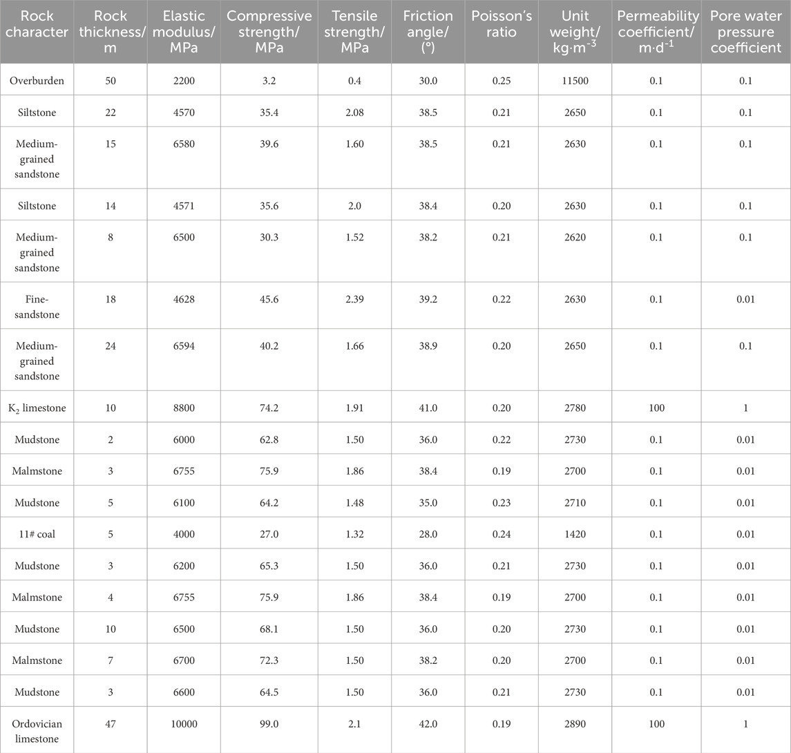
Table 1. Rock mechanical parameters of numerical model.
The calculation model is shown in Figure 1. The rock mass bears dead load and confined water pressure. The boundary conditions of the model were as follows: the left and right boundaries of the model were horizontally fixed and vertically free, the bottom boundary was horizontally unconstrained and vertically fixed. The 180 m high fixed head boundary was set to simulate the confined water pressure of Ordovician limestone. The distributed excavation method was used to simulate the mining of the working face. The open-off cut was located at 150 m to the right of the model. The excavation length of each step was 10 m, a total of 15 steps, and the cumulative excavation was 150 m.
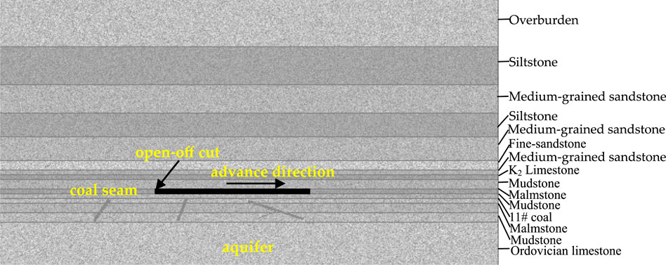
Figure 1. Schematic diagram of RFPA numerical simulation.
2.4 Simulation analysis of water inrush process
The formation process of water inrush channels activated by hidden faults is shown in Figure 2 and Figure 3. According to the simulation results, it can be found that the floor rock layer was damaged below the working face due to the formation of a rapid pressure change zone between the advanced support pressure on one side of the coal pillar below the working face and the pressure relief zone on the goaf side. Due to the presence of hidden faults, the depth of damage to the floor near the fault was much greater than on the other side. Under the action of mining induced stress and confined water pressure, faults exhibit small-scale activation, which was limited to the stress disturbance range in the mining failure zone. The emergence of mining damage areas and fault activation areas has created favorable conditions for the formation of the next step of water inrush channels. When the working face advanced to a distance of 20–30 m from the open-off cut, regional damage begins to occur on the floor (as shown in Figures 2A, B), and cracks within the water conducting fault zone of the floor begin to develop. The first and second hidden faults exhibited a certain range of activated areas (as shown in Figure 3A). The second hidden fault has a relatively larger activation range due to its closer proximity to the goaf. Under the action of mining induced stress and pressurized water pressure (including hydraulic scouring and hydraulic wedging), cracks begin to develop in the water conducting fault zone of the floor, forming a certain range of activation zones within the fault zone, that was, hidden faults were in the activation stage.
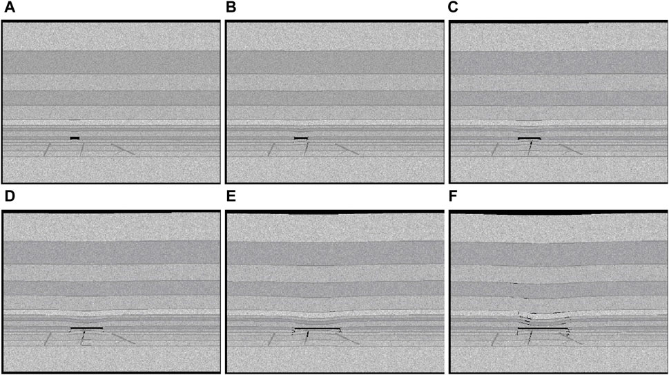
Figure 2. Dynamic distribution law of elastic modulus during mining. (A) Mining 20 m. (B) Mining 30 m. (C) Mining 50 m. (D) Mining 70 m. (E) Mining 100 m. (F) Mining 120 m.
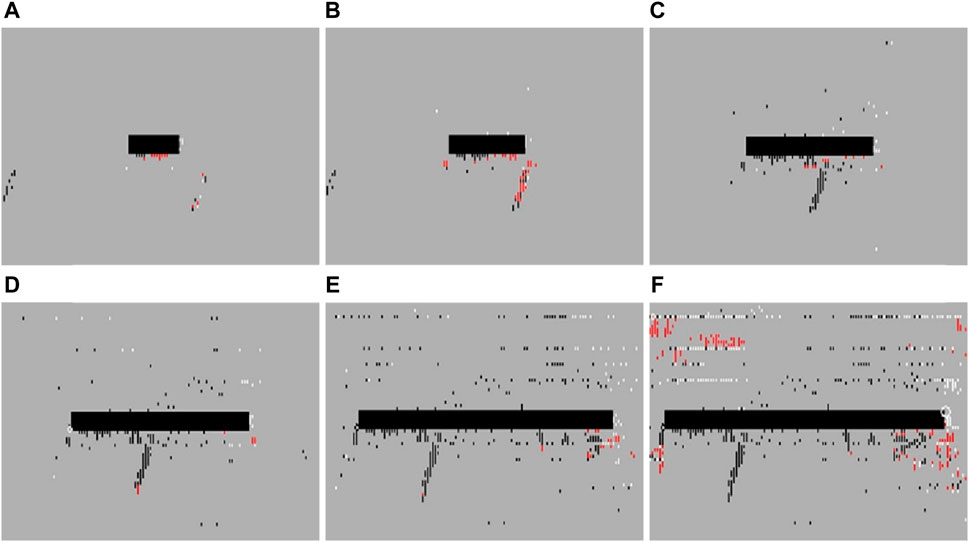
Figure 3. Dynamic distribution of the damage zone (white-shear failure, red-tensile failure, black-cells with damage in all previous steps). (A) Mining 20 m. (B) Mining 30 m. (C) Mining 50 m. (D) Mining 70 m. (E) Mining 100 m. (F) Mining 120 m.
When the working face advanced to 50 m, due to the intensified destructive effect of mining activities on the initial stress field, the mining damaged zone of the floor increases, and downward open cracks appear on the floor. As well, the activated area of hidden faults gradually extends towards the working face. The cracks in the floor damaged zone within the goaf gradually connected with hidden faults, and confined water begins to flow out, as shown in Figure 2B and Figure 3B. After the working face advanced to 70 m, the third hidden fault also begins to locally activate. The fissures in the coal wall develop, and the confined water ascends, interacting with the fracture field of the second fault, further expanding the damage area of the floor strata, corresponding to Figure 2C and Figure 3C. During this process, the floor connected with the water conducting fissure of the second hidden fault, where the water inrush channel gradually formed and the seepage discharge increased, corresponding to Figure 2D and Figure 3D. After the working face advanced to 100 m (as shown in Figure 2E and Figure 3E), the activated area of hidden fault further expands, the aquifer rock mass between the mining damage area and the fault activation area continued to be damaged and destroyed, and the diversion fissure zone continued to expand and connect with each other. As the working face continued to advance, the fissure of the third hidden fault gradually connectd with the mining damage area of the floor. When the excavation reached to 110 m (as shown in Figure 2F and Figure 3F), the seepage passage penetrated. It can be found that the coalescence of water conducting fissures in the middle fault accelerates the expansion speed of the right fault fissure.
The variation character of seepage field in the numerical simulation of the water inrush process raised by activation of hidden faults as shown in Figure 4. From the simulated result it can be found that the mining activities have a significant impact on the permeability of the floor with hidden faults. During the process of advancing the working face, the action of mining stress and confined water made fissures of hidden faults expand rapidly, and the permeability has been greatly improved. At the same time, the confined water within the fault also has a scouring and expansion effect on the fault fissures, which accelerated the development speed of the fissures. New cracks were generated and interconnected, ultimately reduced the permeability and integrity of the aquifer rock mass of the floor. When the working face advanced to 70 m, the mining damage area connected with the conductive layer of the hidden fault, formed the first water inrush channel, and caused water inrush (Figure 4D corresponds to Figure 2D and Figure 3D). As the working face advanced to 110 m, the third water conducting zone of the fault was formed. During the entire advancing process of the working face, the seepage field (shown by the arrow in Figure 4) remained consistent with the fracture propagation direction of the hidden fault, and the seepage field evolved synchronously with the fracture field of the hidden fault. The variation range of the seepage field was the same as the propagation area of cracks (Figures 4A–F; Figures 2A–F; Figures 3A–F). There were spatial and temporal differences in the fracture penetration rules of hidden faults at different positions of the floor. The closer the distance to the goaf, the more likely it was to occur the water inrush raised by activation of hidden faults. With the increased of pressure relief effect in the goaf, the possibility of water inrush from hidden faults gradually increased.
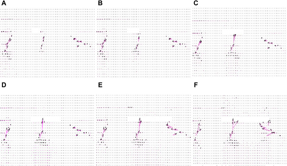
Figure 4. Distribution of flow field. (A) Mining 20 m. (B) Mining 30 m. (C) Mining 50 m. (D) Mining 70 m. (E) Mining 100 m. (F) Mining 120 m.
The coal wall near the working face produced stress release due to excavation unloading, and the value of bearing pressure was small. After the excavation of the coal seam, the overall variation trend of the value of bearing pressure in the direction away from the mining area was: it first increases, and then started to decrease until the initial rock stress state. After the first weighting, as the working face advanced forward, due to the increase in excavation space, the increased in the bearing pressure concentration value caused by the advancing unit distance of the working face gradually decreases, and the variation tends to be flat, as shown in Figure 5. When the working face was advanced by about 95 m–100 m, the support stress of the coal wall was about 4 times the original stress, reached a maximum value of about 35 MPa, and then showed a gradually decreasing trend. As can be seen from Figure 6, the floor forms a stress concentration within a certain range near the open-off cut. As the working face continued to advance, the concentrated stress gradually increased, and the concentrated stress at the corresponding position of the floor below the open-off cut extends to a certain extent to the corresponding position above the goaf, that was, an elastic-plastic high stress zone was formed within 12 m around the open-off cut and the coal wall. The main stress of the protective layer in this range was the largest, and the coal rock undergoes compression shear failure, which could easily connect with the uplift fracture formed by the activation of hidden faults to form a fracture channel. Compared to other areas, due to the largest water head pressure difference between the coal seam and the goaf in this area, it was extremely prone to water inrush, causing accidents.
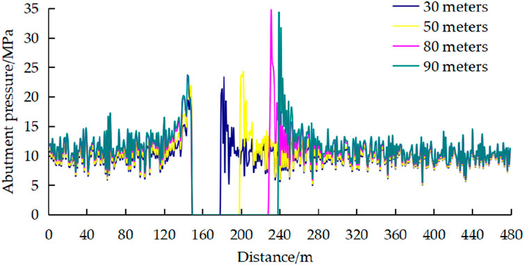
Figure 5. Dynamic distribution law of abutment pressure of middling coal wall during mining.
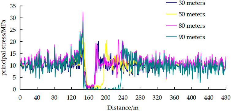
Figure 6. Dynamic distribution of principal stress.
It can be found from Figures 5–7 that the presence of hidden faults has accelerated the destruction process of the water-resisting of floor. As the working face continued to advance, the permeability coefficient of the floor had undergone significant changes. Under the combined action of mining stress and confined water pressure, the confined water flows along the fracture channel from high pressure areas to low pressure areas. Between the initial stage of mining and the range of 50–60 m, the water head pressure gradient near the coal wall at the open-off cut and working face was larger, the stress on the coal wall was not released, its permeability was somewhat reduced, and the corresponding flow rate was also smaller. However, the floor stress in the goaf was released, and the elastic energy was released, resulting in floor heave and tensile cracks. The water head pressure decreased rapidly, and the corresponding flow rate also continuously increased. In particular, with the advancement of the working face, three hidden faults become activated, cracks expand and connect, and the formation of water inrush channels, the water flow increases rapidly, especially after the working face advances to 80 m, the flow distribution characteristics become more obvious.
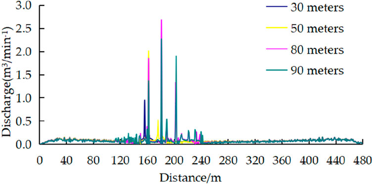
Figure 7. Flow distribution law in the vertical direction of the floor.
Comprehensively analyzed the stress change state, damage zone characteristics, and fracture distribution of the floor with concealed faults, taking into account the change characteristics of mining stress, confined water pressure, seepage velocity, and water inrush quantity, the characteristics of water inrush were summarized as follows: When no faults were encountered in the working face, the failure characteristics were similar to those of the complete floor. When encountering hidden faults, the integrity of the floor decreased, and the damage zone of the floor was easily connected with the aquifer, and water inrush from the floor was easily induced. Due to the high abutment pressure near the coal wall, the head pressure increased, made the risk of water inrush greater. When there were faults behind the working face, seepage mainly occurred in the water inrush channels connected by the faults. Therefore, the existence of faults made the division of water inrush characteristics significantly different from that of the complete floor. Moreover, when there were multiple hidden small faults in the floor, it showed alternating changes between the water inrush growth area and the flow stable area with similar cycle characteristics.
3 Fracture mechanics analysis on water inrush from floor
Before dynamic loads such as roof caving, rock burst, and mine earthquake act on the floor strata, the floor strata have already been subjected to static loads such as initial rock stress and stope abutment pressure. In this case, the dynamic response and dynamic fracture of rock cracks were essentially the result of the combined action of dynamic and static stress fields, so it was closer to engineering practice to attribute them to the superposition of dynamic and static stress fields. According to the theory of fracture mechanics, in the linear elastic range, when cracks have the same propagation mode under multiple loads, the stress intensity factor at the crack tip can be calculated using the superposition method (Gao, 1985). Therefore, in this section, the fault plane was simplified as an ideal crack interface. Using the theory of dynamic fracture mechanics, by analyzing the equivalent stress intensity factors at the crack tip, a criterion for the occurrence of tensile or compressive shear fracture of water-bearing hidden fault cracks under the combined action of dynamic and static loads and its theoretical calculation model were established, the critical dynamic and static load strengths and conditions for crack propagation were derived, and their influencing factors were analyzed. The influence of dynamic load participation on the propagation law of hydrous cracks was discussed. The dynamic stress triggering mechanism of fault activation was analyzed. The water inrush model of the working face floor is shown in Figure 8.
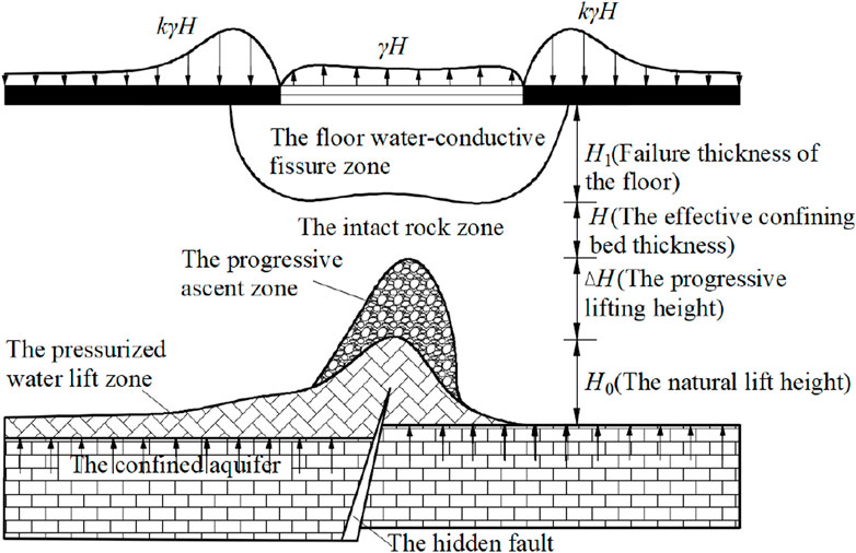
Figure 8. Progressive ascending principle and segregation diagram of coal layer seam (Wang et al., 2018a; Wang and Yao, 2022)
3.1 Stress intensity factors for crack propagation
The hidden faults in the coal seam floor are generally small geological structures with small planar distribution and limited vertical distance, which can be simplified as central oblique cracks under complex stress and osmotic pressure. Combined with the results of numerical simulation, the necessary condition of water inrush from fault is the initiation and propagation of the crack under the action of dynamic and static loads. Assuming that the length of the crack is 2a and the pore water pressure within the crack is p, and assuming that the pore water pressure exerts equal forces along each direction of the crack, the angle between the incident direction of the stress wave and the x-axis is α, the angle between the crack and the vertical principal stress σ1 is β, and the angle at which the polar coordinates are constructed with the crack tip as the origin is τ (As shown in Figure 9). When the influence of dynamic load effect was not considered, the static stress state on the crack surface can be expressed as (positive in tension and negative in compression in fracture mechanics):
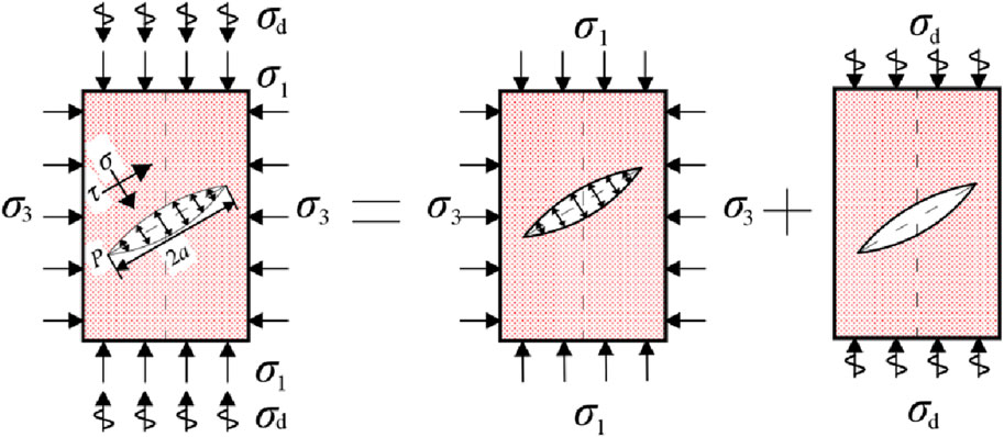
Figure 9. Calculation model for the crack growth under static-dynamic loading.
From Eq. 11, it can be found that there are both normal and shear stresses on the cracks, and the propagation and instability mode of the cracks is the I-II composite type. According to whether the normal stress of the fracture surface is tensile or compressive, the cracks can be divided into open cracks and closed cracks, thereby determining whether the expansion mode of rock mass cracks is compression-shear composite fracture or tension-shear composite fracture. In fracture mechanics, crack propagation and failure are divided into I-II type tension-shear propagation and II type compression-shear propagation based on whether the normal stress of the crack is a tensile or a compressive stress. According to the theory of fracture mechanics, in the linear elastic range, when cracks have the same propagation mode under multiple loads, the stress intensity factor at the crack tip can be calculated using the superposition method (Fan, 2006). Therefore, the dynamic and static stress intensity factors included can be used to obtain the equivalent stress intensity factors for cracks under combined dynamic and static loads using the linear elastic superposition principle, namely,:
where KE is the stress intensity factor for hydrous cracks, KEJ is the static stress intensity factor under static loads, KED is the dynamic stress intensity factor under dynamic loads, and the crack propagation mode generated by static load and dynamic load is the same.
The type II dynamic stress intensity factor generated by dynamic load can be calculated by the following equation (Fan, 2006)
where
(1) TypeⅠ-Ⅱ tension-shear composite propagation
When the pore water pressure in the fracture is greater than the normal stress generated by the remote stress on the fracture surface, the normal stress on the fracture surface is tensile stress, and the fracture is in an open state. The propagation problem of an open fracture belongs to the I-II tension-shear composite type. When the normal stress at the hydrous crack surface of the rock mass is the tensile stress, the crack will expand under tensile stress. The approximate fracture criteria commonly used in engineering (Huang et al., 2000; Wang et al., 2004) are used for analysis, and the criterion for instability propagation can be expressed as
where KIC is the stress intensity factor for I-II type tension-shear propagation; KI and KII are Type I and Type II stress intensity factors caused by static loads (crustal stress, pore water pressure, etc.), as shown in Eq. 14; KId and KIId are Type I and Type II stress intensity factors caused by dynamic loads
Taking Eq. 11 into Eq. 15, the static stress intensity factor at the crack tip under the static load can be obtained
According to Eq. 3, the maximum values of KId and KIId can be obtained after ignoring time and phase, and they are substituted with Eq. 13 and (16) into Eq. 14 to obtain the stress intensity factor KIC for crack failure of tension-shear propagation under the dynamic load
At this time, the corresponding water pressure p is the critical water pressure for the tension-shear propagation mode of the crack, recorded as Plj
(2) Type II compression-shear propagation
When the normal stress at the hydrous crack surface of the rock mass is compressive stress, the crack will close under the compressive stress, forming a pure type II compression-shear propagation mode (Wang et al., 2010). According to the maximum hoop stress theory (Li and Yang, 2006; Li et al., 2015), a polar coordinate system is established with the crack tip as the polar coordinate origin. The hoop stress can be expressed as
The angle between the section where the maximum hoop stress σθmax is located and the original crack line can be used to determine the initial crack angle of crack propagation θ0. At this time, the stress intensity factor for crack initiation can be expressed as
When the influence of crack thickness and tip curvature radius is ignored, the initial crack angle of crack compression-shear propagation is always arctan
Combined with the results of numerical simulation, it can be concluded that the water inrush from the floor of the hidden fault is caused by dual actions: ① the dynamic and static load actions caused by the collapse of overlying strata lead to the activation of the water-bearing hidden fault; ② under the continuous action of high pressure water pressure, the crack of rock mass weakens and changes the effective stress between cracks of rock mass, which causes the crack to expand and intersect, the permeability has been greatly improved, and the confined water in the fault has the effect of scouring and dilatancy on the cracks, which accelerates the growth of cracks. The closer to the goaf, the more likely it is for hidden fault activation and water inrush to occur.
The critical water pressure for the compression-shear failure mode of cracks at different depths is much smaller than the critical water pressure for the tension-shear failure mode of cracks, and the critical water pressure for the compression-shear failure of cracks is easier to meet than the critical water pressure required for the tension-shear failure. Therefore, in natural construction force environment such as in-situ stress and high water head pressure, hydraulic fracturing of rock mass under the disturbance of engineering measures such as excavation is the compression-shear failure mode (Wang et al., 2004; Chen et al., 2007; Wang and Yao, 2022). When the normal stress at the hydrous crack surface of the rock mass is compressive stress, the cracks undergo closure and compaction, and the cracks appear to be uniformly relieved, while transmitting corresponding shear stress and normal stress. The shear stress can cause crack surface growth. Due to the crack closure and compaction, the frictional force will be generated along the crack surface under the action of normal stress to resist the propagation and sliding of the crack surface. According to this, the effective shear stress on the crack of the floor rock mass causes the compressive-shear failure and water inrush in the fractured rock mass, and the effective shear stress can be expressed as
where f is the coefficient of friction, c is the cohesion of the crack surface.
According to Eq. 22, adjust the KII in Eq. 15 to:
The calculation method is the same as that for the stress intensity factor for tension-shear propagation failure. According to Eq. 18, the maximum value of
At this point, the corresponding water pressure p is the critical water pressure for the compression-shear propagation mode of the crack under the superimposed dynamic and static loads, recorded as Pyj
3.2 Minimum safety thickness of floor
The process of hydraulic fracturing of hydrous cracked rock mass under dynamic loads requires three stages, namely, the splitting potential period of cracked rock mass, the crack propagation period of rock mass, and the crack coalescence and expansion period of rock mass. During the splitting potential period of cracked rock mass, the water pressure Ps at the edge of the crack ≥ the water pressure Pc at the tip of the crack, and the cracked rock mass undergoes propagation and splitting. With the increase of time, the water pressure Pt at the crack tip gradually develops into karst water pressure, and the dynamic load disturbance causes damage to the rock mass, making the critical water pressure Pc of the cracked rock mass continuously decrease. When Pt=Ps>Pc, the accumulation of fracture energy ends and enters the rock mass crack propagation period (Guo and Qiao, 2012; Guo J. Q. et al., 2018).
The excavation disturbance of the working face has changed the effective stress between rock cracks, and seriously destroys the static stability of the water-resisting layer of the floor. It not only increases the depth of floor plate failure and the height of the pressurized water bearing uplift zone, but also greatly promotes the expansion of water bearing cracks and the activation of floor plate faults, leading to the activation of hidden fault tip cracks and the occurrence of propagation and penetration, resulting in a significant improvement in permeability, until the formation of water-inrush channel induced water-inrush disaster.
The excavation disturbance of the working face changes the effective stress between the cracks in the rock mass, leading to the activation of the cracks at the tip of the hidden fault and the occurrence of propagation and coalescence until the formation of water inrush channels, inducing water inrush disasters. Therefore, the rock mass between the floor with hidden faults and the water-bearing hidden faults is divided into two parts, namely, the mining damage and destruction zone Lc, and the distance between the crack tip and the mining damage zone of the floor is the complete rock layer zone Ls (Chen et al., 2007; Yang and Zhang, 2016), as shown in Figure 8. The mining of the working face has formed a mining damage and destruction zone Lc, whose size can be determined through monitoring measurements (Zhang et al., 2013; Zhang et al., 2022). Whether the hydraulic fracturing zone can reach the thickness of the complete rock layer zone during mining requires theoretical analysis to determine. It is beneficial to take reinforcement measures in advance to ensure safe mining of the working face.
(2) Complete rock layer zone Ls
Under the action of high water pressure, the compressive bearing capacity of rock mass under certain geometric dimensions is limited. When the ultimate compressive bearing capacity of rock mass is exceeded, the rock mass will rupture and damage along its weakest point. According to Eq. 25, the splitting failure of cracked rock mass is affected by σ1,σ3 and dynamic stress intensity factors
where Ls is the distance from the edge of the crack zone of the hidden fault to the innermost edge of the excavation disturbance damage zone of the working face (i.e., the thickness of the complete rock layer zone), and R is the equivalent radius.
During the advancing process of the working face, the distance from the edge of the initial crack zone of the hidden fault to the innermost edge of the mining damage zone of the working face is Ls (complete rock layer zone). If the critical water pressure for hydraulic fracturing here is less than the pressurized water pressure, fracturing failure occurs. At this point, Ls is the thickness of the hydraulic fracturing zone. According to the relationship between the lateral pressure coefficient and the critical water pressure, when the lateral pressure coefficient is 1, Ls can be expressed as
Take the value of λx as 1, and the critical water pressure for the propagation failure of hydrous cracks in the rock mass within the section obtained from Eq. 25 is:
Take σ1= λσ3= λγH, γ is the weight of the overburden stratum. Based on the analysis of Ps>Plj and Ps<Plj, the calculation equation for the thickness Ls of the complete rock layer zone under the combined action of dynamic and static loads are derived, as shown in Eq. 29 (Ps>Plj) and Eq. 30 (Ps<Plj)
Note: In the calculation process of Ls, in order to unify the units, this item
Based on the above analysis, when there is high pressure water in the floor of water-bearing hidden faults, coal mining should be carefully carried out, construction scheme should be adjusted, or effective measures should be taken to ensure construction safety and prevent water inrush disasters. At this time, the minimum safety thickness in the floor of the working face is
The equation for calculating the minimum safe thickness of fractured rock mass was obtained by substituting the mining damage zone of the floor Lc (which can be obtained through actual measurement) and the hydraulic fracturing zone Ls into Eq. 31. Ls is calculated by choosing Eq. 29 when Ps>Plj and Eq. 30 when Ps<Plj.
From the above analysis, it can be concluded that the effect of dynamic loads has a great promoting effect on the pressure reduction and propagation of hydrous cracks. Dynamic load affects the fracture propagation mode by increasing pore water pressure, and the effect of dynamic loads will lead to the increase in pore pressure within the fracture, reducing the effective stress on the fracture surface; In addition, within the certain range of fracture dip angles, the effect of dynamic compressive stress will directly change the stress intensity factor at the crack tip, making the stress intensity factor at the crack tip increase. When the stress intensity factor reaches a critical value, it will lead to fracture propagation and coalescence failure of the rock mass.
Combined with theory and numerical simulation analysis, it can be concluded that when there are hidden faults in the floor, not only the failure depth of the floor and the height of the pressurized water bearing uplift zone increase rapidly under the combined action of dynamic and static loads, it also promotes the expansion of water-bearing cracks and the activation of floor hidden faults, and aggravates the formation of floor water-conducting channels, the risk of failure and instability of water-bearing hidden faults is greater than that of static loading, and it is easier to cause water inrush from floor.
3.3 Analysis on factors affecting the minimum safe thickness of the outburst prevention layer
From Equations (29), (30), and (31), it can be found that the minimum safe thickness of the outburst prevention layer of the floor with hidden faults in the working face is related to physical quantities such as the Ordovician limestone water pressure, the distribution characteristic parameters of hidden faults, and the mechanical parameters of the rock mass of the outburst prevention layer. According to Equation (31), the variation trend of the minimum safe thickness of the outburst prevention rock layer with various influencing factors can be analyzed, as shown in Figure 10. When the influence of a parameter was not discussed, the parameter was taken as a fixed value in the calculation of the minimum safe thickness, assuming that the pore water pressure Ps=2 MPa, and the dip angle of the hidden fault fissure β=30°, measured lateral pressure coefficient n=0.6, γ=26.50 kN/m3, type II compression-shear propagation stress intensity factor of the floor rock layer KIIC=4.68 MN/m3/2, H=45 m, the hydrous crack’s length 2a is equal to the initial fracture zone thickness of 3.4m, the friction coefficient f is 0.92, the cohesion force of crack surface c=1.4 MPa, R=5.65 m, and the mining damage zone thickness of the floor Lc=4.5 m (Discuss respectively that ps, a, and H are the mining depth of the working face and the crack inclination angle is α).
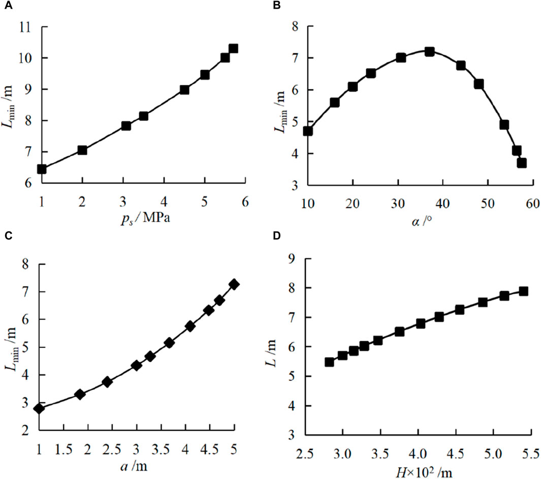
Figure 10. Relationship between minimun safe thickess of seam floor strata and each influential factor. (A) the pore water pressure, (B) crack dip angle, (C) crack length, and (D) mining depth of the working face.
By analyzing the variation trend of each curve in Figure 10, it can be found that with the increases of ps, the minimum safe thickness of the outburst prevention layer approximately linearly increases, and with the pressure of water increases, the stress acting on the crack tip increases, making it easier for the crack to expand, resulting in an increase in the thickness of the outburst prevention layer. With the increases of the inclination angle of the crack, the thickness of the outburst prevention layer first increases and then decreases. When the dip angle α varies in the interval of 10°–60°, L increases from 4.74 m to 7.3 m and then decreases to 3.72 m. With the increases of crack length a, L continues to increase at a certain rate, and L continues to increase with the increase of crack length a. The crack length increases, so that the crack extension length was reduced, making it easier to penetrate the floor and form the water inrush channel. With the increases of mining depth H, the thickness of the outburst prevention layer continues to increase, the geostress increases, and the abutment pressure increase during coal mining, which makes the working face prone to water inrush disasters. Therefore, a larger anti-collision layer was needed to ensure the safety of the working face.
4 Engineering example
Combined with the theoretical analysis results, the water inrush risk of coal mining face in the literature (Chen et al., 2007) was judged, and the minimum thickness of the outburst prevention layer of the floor was calculated to verify the rationality of the theoretical analysis. The following parameters were determined based on the actual mining situation of the working face: the pore water pressure is Ps=1.5 MPa, and the dip angle of the buried fault is α= 60°, the vertical stress is σ1=6 MPa, the horizontal stress is σ3=3 MPa, the lateral pressure coefficient is n=0.6, γ=26.50 kN/m3, the type II compression-shear propagation stress intensity factor
According to Equation (28), it can be determined that the critical water pressure for compression-shear propagation failure of cracks under the dynamic load stress Plj=1.63 MPa, Plj>Ps, that was, the confined water pressure of the floor was greater than the critical water pressure for compression-shear propagation failure of hidden fault cracks. Therefore, it was necessary to calculate the thickness Ls of the complete rock zone by Equation (29). By substituting the parameters of the working face in the example into Equation (29), it was calculated that Ls=30.4 m, which was very close to the calculated result of 30 m in the example, verified the correctness of the theoretical analysis. According to the actual measurement, the mining damage depth of the working face was Lc=11.42 m. According to the theoretical analysis results, the minimum safety thickness of the floor to ensure that the working face does not suffer from water inrush disasters can be calculated by substituting Equation (31), L=41.82 m. Through the actual measurement, it was found that the distance from the floor of the working face to the fault all exceeds 42 m, which can effectively ensure the stability of the working face. Therefore, this method is relatively reasonable and feasible, and can be used to guide coal mining in areas with high confined water, providing a reference for preventing water inrush disasters from occurring in the floor.
5 Conclusion
In this paper, the formation and evolution mechanism of water inrush channels from the floor with hidden faults under dynamic and static loads were comprehensively studied, systematically described the entire process of activation, penetration, and communication of hidden faults to form water inrush channels through numerical simulation, explored the water inrush mechanism of the floor with hidden faults through fracture dynamics analysis, and analyzed the critical water pressure for fracture failure and the minimum safe thickness of the floor. The main conclusions are as follows.
(1) The existence of hidden faults makes the characteristics of water inrush from the floor significantly different from those of the complete floor. The mining stress and confined water action made the hidden fault cracks expand rapidly, and the permeability has been greatly improved. At the same time, the confined water within the fault also had a scouring and expansion effect on the cracks, accelerated the development speed of the cracks. There were spatial and temporal differences in the fracture penetration rules of hidden faults at different positions of the floor. The closer the distance to the goaf, the more likely it was to occur the water inrush raised by activation of hidden faults. When there were multiple hidden small faults in the floor, there was an alternating change between the sudden water increase zone and the stable flow rate zone, which exhibited similar cyclic characteristics.
(2) The effect of dynamic load seriously damages the static stability of the floor aquifer, which not only increased the depth of floor damage and the height of the pressurized aquifer uplift zone, but also greatly promoted the expansion of water aquifer cracks and the activation of the floor faults, exacerbated the formation of water conducting channels and greatly increased the possibility of water inrush from the floor.
(3) Based on the theory of fracture dynamics, the strength criteria for tension-shear and compression-shear fracture of hydrous cracks under combined dynamic and static loads were established, and the corresponding expressions of critical dynamic load stresses were derived. The calculation equation for critical water pressure when cracks undergo compression-shear propagation failure under dynamic and static loads was further derived. The calculating equation that reasonably reflects the minimum safe thickness of the complete rock layer zone of the floor under the dynamic load stress, mining action, and water pressure was obtained, and the effects of confined water pressure, crack length, dip angle, and mining depth on it were discussed. Finally, the theoretical results are verified by engineering examples.
Data availability statement
The original contributions presented in the study are included in the article/supplementary material, further inquiries can be directed to the corresponding author.
Author contributions
XZ: formal analysis, methodology, writing–review and editing. DY: data curation, visualization, writing–original draft, formal analysis, methodology, writing–review and editing. YZ: funding acquisition, project administration, supervision, writing–review and editing. AZ: funding acquisition, project administration, supervision, writing–review and editing.
Funding
The author(s) declare that financial support was received for the research, authorship, and/or publication of this article. This research was funded by the National Natural Science Foundation of China (Grant no. 51704173), the Key R and D Projects of Shandong Province (Grant no. 2019GSF111029), the Science and Technology Program of Colleges and Universities in Shandong Province (Grant no. J17KA203), and the Qingdao Postdoctoral Researcher Application Research Project, and Project funded by the Open Project of the Engineering Laboratory of Deep Mine Rockburst Disaster Assessment, Shandong Province (Grant no. LMYK2021007).
Conflict of interest
The authors declare that the research was conducted in the absence of any commercial or financial relationships that could be construed as a potential conflict of interest.
Publisher’s note
All claims expressed in this article are solely those of the authors and do not necessarily represent those of their affiliated organizations, or those of the publisher, the editors and the reviewers. Any product that may be evaluated in this article, or claim that may be made by its manufacturer, is not guaranteed or endorsed by the publisher.
References
Chen, L. L., Wang, E. Y., and Lian, Y. X. (2015). Numerical simulation analysis of water inrush risk of buried faults in coal seam floor. Coal Sci. Technol. 43, 41–44.
Chen, Z. H., Feng, J. J., Xiao, C. C., and Li, R. H. (2007). Fracture mechanical model of key roof for fully-mechanized top-coal caving in shallow thick coal seam. J. China Coal Soc. 32, 449–452.
Chen, Z. H., Hu, Z. P., Li, H., and Chen, Q. F. (2011). Fracture mechanical model and criteria of insidious fault water inrush in coal mines. J. China Univ. Min. Technol. 40, 673–677.
Cui, H. Q., and Yao, N. G. (2011). Numerical simulation of the coal petrology stress distribution characteristic in the fault zone. J. Henan Univ. Technol. Sci. Ed. 30, 27–30. doi:10.16186/j.cnki.1673-9787.2011.05.021
Fan, T. Y. (2006). Principles and applications of fracture dynamics[M], 201. Beijing: Beijing University of Technology Press, 696.
Gao, M. S., Liu, Y. M., Zhao, Y. C., Gao, X. J., and Wen, Y. Y. (2017). Roof burst instability mechanism and dynamic characteristic of deep coal roadway subjected to rock burst. J. China Coal Soc. 42, 1650–1655. doi:10.13225/J.CNKI.JCCS.2016.1464
Gao, X. F., Zhang, Y. J., Cheng, Y. X., Yu, Z. W., Hu, Z. J., and Huang, Y. B. (2020). A thermal-hydraulic-mechanical coupling study of heat extraction from the geothermal reservoir with a discrete fracture network. Geofluids 2020, 1–18. doi:10.1155/2020/8875918
Gao, X. F., Zhang, Y. J., Cheng, Y. X., Yu, Z. W., and Huang, Y. B. (2022). Impact of fractures with multi-scale aperture variability on production observations of geothermal reservoir units. J. Hydrology 615, 128693. doi:10.1016/j.jhydrol.2022.128693
Gou, P. F., and Hu, Y. G. (2006). Effect of faults on movement of roof rock strata in gateway. J. Min. Saf. Eng. 23, 285–288.
Guo, J. Q., Chen, J. X., Chen, F., Luo, Y. B., and Liu, Q. (2018b). Water inrush criterion and disaster process of karst tunnel face with intermittent joints. China J. Highw. Transp. 31, 118–129.
Guo, J. Q., and Qiao, C. S. (2012). Study on water inrush mechanism and safe thickness of rock wall of karst tunnel face. J. China Railw. Soc. 34, 105–111. doi:10.3969/j.issn.1001-8360.2012.03.018
Guo, W. J., Zhang, S. C., Sun, W. B., and Chen, J. T. (2018a). Experimental and analysis research on water inrush catastrophe mode from coal seam floor in deep mining. J. China Coal Soc. 43, 219–227.
Hu, X. Y., Wang, L. G., Lu, Y. L., and Y, M. (2014). Analysis of insidious fault activation and water inrush from the mining floor. Int. J. Min. Sci. Technol. 24 (4), 477–483. doi:10.1016/j.ijmst.2014.05.010
Huang, B. X., Liu, F., Wang, Y. X., Wang, X., and Ji, W. O. (2010). Development of water conductive fissures in hidden reversed fault in thinning-out overlying strata of a stope. J. Min. Saf. Eng. 27, 377–381.
Huang, H., and Wang, J. M. (2015). Research on water inrush from the blind fault of coal floor by physical experiment. J. North China Inst. Sci. Technol. 12, 11–16.
Huang, R. Q., Wang, X. N., and Chen, L. S. (2000). Hydro-splitting off analysis on underground water in deep-lying tunnels and its effect on water gushing out. Chin. J. Rock Mech. Eng. 19, 573.
Jiang, Y. D., Wang, T., Zhao, Y. X., and Wang, C. (2013). Numerical simulation of fault activation pattern induced by coal extraction. J. China Univ. Min. Technol. 42, 4–8. doi:10.13247/j.cnki.jcumt.2013.01.002
Kang, H. P., Xu, G., Wang, B. M., Wu, Y. ;Z., Jiang, P. F., Pan, J. F., et al. (2019). Forty years development and prospects of underground coal mining and strata control technologies in China. J. Min. Strata Control Eng. 1, 7–39. doi:10.13532/j.jmsce.cn10-1638/td.2019.02.002
Li, H. Y., Li, X. G., Ma, M. Z., Liu, H., and Yang, Y. (2022). Model experimental study on influence of buried fault dislocation on shield tunnel. J. Zhejiang Univ. Eng. Sci. 56, 631. doi:10.13532/j.jmsce.cn10-1638/td.2019.02.002
Li, L. C., Tang, C. A., Li, G., and Yang, T. H. (2009a). Damage evolution and delayed groundwater inrush from micro faults in coal seam floor. Chin. J. Geotechnical Eng. 31, 1838–1844.
Li, L. C., Tang, C. A., Liang, Z. Z., Ma, T. H., and Zhang, Y. B. (2009b). Numerical analysis of pathway formation of groundwater inrush from faults in coal seam floor. Chin. J. Rock Mech. Eng. 28, 290–297.
Li, L. C., Yang, T. H., Liang, Z. Z., Zhu, W. C., and Tang, C. A. (2011). Numerical investigation of groundwater outbursts near faults in underground coal mines. Int. J. Coal Geol. 85, 276–288. doi:10.1016/j.coal.2010.12.006
Li, S. C., Yuan, Y. C., Li, L. P., Ye, Z. H., Zhang, Q. Q., and Lei, T. (2015). Study on water inrush mechanism and minimum safe thickness of karst tunnel face under drilling and blasting construction. Chin. J. Geotechnical Eng. 37, 313–320. doi:10.11779/CJGE201502015
Li, S. G., Lv, J. G., Jiang, Y. D., and Jiang, W. Z. (2014). Coal bump inducing rule by dip angles of thrust fault. J. Min. Saf. Eng. 31, 869–875. doi:10.13545/j.issn1673-3363.2014.06.007
Li, Y. P., and Yang, C. H. (2006). Influence of geometric characteristics of pre-existing cracks on mixed mode cracks under compression-shear loading. Chin. J. Rock Mech. Eng. 25, 462–466. doi:10.1007/s10483-006-0101-1
Li, Z. H., Dou, L. ;M., Lu, Z. Y., Lu, X. W., and Wang, G. R. (2010). Study of the fault slide destabilization induced by coal mining. J. Min. Saf. Eng. 27, 499–504.
Liu, J. G., Qiu, X. Y., Li, Y. B., and Gao, H. C. (2017). Research on the theory and Technology of microseismic monitoring and early warning for mine water damage. Beijing: Coal Industry Press.
Liu, Z. W., Liu, Q. S., and Liu, Y. (2020). Classification of hidden faults in coal seam floor and measures for water inrush prevention. Coal Geol. Explor. 48, 141–146. doi:10.3969/i.issn.1001-1986.2020.02.022
Lv, J. G., Jiang, Y. D., Li, S. G., Ren, S. D., Jiang, W. Z., and Zhang, Z. C. (2014). Characteristics and mechanism research of coal bumps induced by faults based on extra thick and hard roof. J. China Coal Soc. 39, 1961–1969. doi:10.13225/j.cnki.jccs.2013.1325
Ma, D., Duan, H. Y., Zhang, J. X., and Bai, H. B. (2022b). A stateoftheart review on rock seepage mechanism of water inrush disaster in coal mines. Int. J. Coal Sci. Technol. 4, 50–28. doi:10.1007/s40789-022-00525-w
Ma, D., Duan, H. Y., Zhang, J. X., Liu, X. W., and Li, Z. H. (2022a). Numerical simulation of water–silt inrush hazard of fault rock: a three-phase flow model. Rock Mech. Rock Eng. 55, 5163–5182. doi:10.1007/s00603-022-02878-9
Peng, S. P., Meng, Z. P., and Li, Y. L. (2001). Similarity simulation study on the effect of fault on roof stability. Coalf. Geol. Explor. 29, 1–4.
Shi, B. Q., and Hou, Z. J. (2011). Mechanical analysis of fault activation water inrush in over burden rock and its application. Rock Soil Mech. 32, 3053–3057. doi:10.16285/j.rsm.2011.10.032
Sun, Y. J., Zuo, J. P., Li, Y. B., Liu, C. H., Li, Y. H., and Shi, Y. (2017). Micro-seismic monitoring on fractured zone and water inrush mechanism analysis of deep mining above aquifer in Xingdong coalmine. J. China Coal Soc. 38, 2335–2342. doi:10.16285/j.rsm.2017.08.022
Wang, J. M., Chen, Z. H., Zhang, L. F., Zhou, Z. H., Qian, F., and Zhou, H. J. (2020). Instability mechanism of counter-tilt layered rock slope by fracture mechanics analysis. Chin. J. Comput. Mech. 37, 75–82.
Wang, J. S., and Yao, D. X. (2022). Physical simulation study on dynamic monitoring of water inrush from concealed fault in confined water. Chin. J. Undergr. Space Eng. 18, 681–689.
Wang, J. S., Yao, D. X., and Huang, H. (2018a). Critical criterion and physical simulation research on progressive ascending water inrush in hidden faults of coal mines. J. China Coal Soc. 43, 2014–2020. doi:10.13225/j.cnki.jccs.2017.1252
Wang, J. S., Yao, D. X., and Huang, H. (2018b). Critical criterion and physical simulation research on progressive ascending water inrush in hidden faults of coal mines. J. China Coal Soc. 43, 2014–2020. doi:10.13225/j.cnki.jccs.2017.1252
Wang, J. X., Feng, B., Zhang, X. S., Tang, Y. Q., and Yang, P. (2010). Fracture mechanical model and hydrochemical-hydraulic coupled damage evolution equation of limestone. J. Tongji Univ. Nat. Sci. 29, 1363–1370. doi:10.1007/BF02911033
Wang, Q., Li, S. C., Li, Z., Li, W. T., Jiang, B., Wang, D. C., et al. (2012). Analysis of roof collapse mechanism and supporting measures in fault zone of coal roadway. Rock Soil Mech. 33, 3093–3101. doi:10.16285/j.rsm.2012.10.024
Wang, Y., Chen, Q., Wei, Y. Y., and Chen, L. (2004). Water-rock interaction mechanism in deep-buried tunnels in karst area. China Railw. Sci. 25, 55–58. doi:10.1007/BF02911033
Wu, Q. (2014). Progress, problems and prospects of prevention and control technology of mine water and reutilization in China. J. China Coal Soc. 39, 795–805. doi:10.13225/j.cnki.jccs.2014.0478
Wu, Q., and Li, B. (2016). Determination of variable weight interval and adjust weight parameters in the variable weight assessment model of water inrush from coal floor. J. China Coal Soc. 46, 2143–2148. doi:10.13225/j.cnki.jccs.2015.1197
Wu, Q., Wang, M., and Wu, X. (2004). Investigations of groundwater bursting into coal mine seam floors from fault zones. Int. J. Rock Mech. Min. Sci. 41, 557–571. doi:10.1016/j.ijrmms.2003.01.004
Xie, H. P., Gao, F., and Ju, Y. (2015). Research and development of rock mechanics in deep ground engineering. Chin. J. Rock Mech. Eng. 34, 2161–2178. doi:10.13722/j.cnki.jrme.2015.1369
Xu, J. P., Zhang, F. C., Gui, H., and Zhang, T. J. (2012). Characteristics and experimental study of water conduction caused by fault activation due to mining. J. China Univ. Min. Technol. 41, 415–419.
Yang, D. F. (2021). Analysis of fracture mechanics theory of the first fracture mechanism of main roof and support resistance with large mining height in a shallow coal seam. Sustainability 13 (4), 1678. doi:10.3390/su13041678
Yang, D. F., Chai, M., Jiang, B. W., Li, B., Chai, J. L., and Zhao, X. W. (2016a). Fracture mechanics analysis on water Inrush by mining-induced activation of floor containing hidden faults. Saf. Coal Mines 47, 198–201. doi:10.13347/j.cnki.mkaq.2016.09.056
Yang, D. F., Chen, Z. H., Xi, J. Y., Hong, Q. F., and Zhang, S. S. (2015). Fracture mechanics analysis of supports crushing while key roof cutting in shallow seam. J. Northeast. Univ. Nat. Sci. 36, 106–110.
Yang, D. F., Zhang, L. F., Chai, M., Li, B., and Bai, Y. F. (2016b). Study of roof breaking law of fully mechanized top coal caving mining in ultra-thick coal seam based on fracture mechanics. Rock Soil Mech. 37, 2034–2039. doi:10.16285/j.rsm.2016.07.026
Yang, Z. H., and Zhang, J. H. (2016). Minimum safe thickness of rock plug in karst tunnel according to upper bound theorem. J. Central South Univ. 23, 2346–2353. doi:10.1007/s11771-016-3293-8
Yuan, F. Z., Ma, K., Zhuang, D. Y., Wang, Z. W., and Sun, X. Y. (2019). Preparation mechanism of water inrush channels in bottom floor of Dongjiahe coal mine based on microseismic monitoring. J. China Coal Soc. 44, 1846–1856. doi:10.13225/j.cnki.jccs.2018.0941
Zhang, J. G., Miao, X. X., Huang, Y. L., and Li, M. (2014). Fracture mechanics model of fully mechanized top coal caving of shallow coal seams and its application. Int. J. Min. Sci. Technol. 24, 349–352. doi:10.1016/j.ijmst.2014.03.011
Zhang, L., and Liu, Y. Q. (2016). Stress control for coal and gas outburst on a fault plane. Chin. J. Geotechnical Eng. 38, 712–717.
Zhang, P. S., Yan, W., Zhang, W. Q., Shen, B. T., and Wang, H. (2016). Mechanism of water inrush due to damage of floor and fault activation induced by mining coal seam with fault defects under fluid-solid coupling mode. Chin. J. Geotechnical Eng. 38, 877–889. doi:10.11779/CJGE201605013
Zhang, P. S., Yan, W., Zhang, W. Q., Yang, Y. W., and An, Y. F. (2018). Study on influencing factors of floor water inrush induced by mining of coal seam with hidden fault. J. Min. Saf. Eng. 35, 765–772. doi:10.13545/j.cnki.jmse.2018.04.014
Zhang, R., Jiang, Z. Q., Li, X. H., Cao, H. D., and Sun, Q. (2013). Study on the failure depth of thick seam floor in deep mining. J. China Coal Soc. 38, 67–72.
Zhang, S. C., Guo, W. J., Li, Y. Y., Sun, W. B., and Yin, D. W. (2017). Experimental simulation of fault water inrush channel evolution in a coal mine floor. Mine Water and Environ. 36, 443–451. doi:10.1007/s10230-017-0433-9
Zhang, S. C., Guo, W. J., Sun, W. B., Li, Y. Y., and Wang, H. L. (2015). Experimental research on extended activation and water inrush of concealed structure in deep mining. Rock Soil Mech. 36, 3111–3120. doi:10.16285/j.rsm.2015.11.010
Zhang, Y., and Pang, Y. H. (2010). Water inrush mechanical model based on a theory of coupled stress-seepage. J. China Univ. Min. Technol. 39, 659–664.
Zhang, Y. J., Zhang, F. D., Zhang, Z. W., Sun, L., and Li, Y. W. (2022). Fullspace multi-parameter cooperative monitoring of failure hierarchy characteristics of mining coal seam floor. Coal Sci. Technol. 50, 86–94. doi:10.13199/j.cnki.cst.2021-0170
Zhao, J. W., Zhou, H. W., Xue, D. J., Su, T., Deng, H. L., and Yang, H. Z. (2019a). Expansion law of seepage path in the concealed structural floor of coal seam in deep confined water. J. China Coal Soc. 44, 1836–1845. doi:10.13225/j.cnki.jccs.2018.0844
Zhao, J. W., Zhou, H. W., Xue, D. J., Su, T., Deng, H. L., and Yang, H. Z. (2019b). Expansion law of seepage path in the concealed structural floor of coal seam in deep confined water. J. China Coal Soc. 44, 1836–1845. doi:10.13225/j.cnki.jccs.2018.0844
Keywords: dynamic load, crack propagation, water inrush, hidden fault, safe thickness
Citation: Zhao X, Yang D, Zhu Y and Zeng A (2024) Analysis on numerical simulation and fracture mechanics model of water inrush of floor with hidden faults under dynamic and static loads. Front. Earth Sci. 12:1352992. doi: 10.3389/feart.2024.1352992
Received: 09 December 2023; Accepted: 07 May 2024;
Published: 29 August 2024.
Edited by:
Davide Tiranti, Agenzia Regionale per la Protezione Ambientale del Piemonte (Arpa Piemonte), ItalyReviewed by:
Dan Ma, China University of Mining and Technology, ChinaYan Chen, Henan Polytechnic University, China
Kai Huang, Anhui Jianzhu University, China
Copyright © 2024 Zhao, Yang, Zhu and Zeng. This is an open-access article distributed under the terms of the Creative Commons Attribution License (CC BY). The use, distribution or reproduction in other forums is permitted, provided the original author(s) and the copyright owner(s) are credited and that the original publication in this journal is cited, in accordance with accepted academic practice. No use, distribution or reproduction is permitted which does not comply with these terms.
*Correspondence: Dengfeng Yang, eWFuZ19kZW5nZmVuZ0BxdXQuZWR1LmNu