 Xinyu Kou
 Xiaojun Li1
 Yi Rui
94% of researchers rate our articles as excellent or good
Learn more about the work of our research integrity team to safeguard the quality of each article we publish.
Find out more
ORIGINAL RESEARCH article
Front. Earth Sci., 08 November 2023
Sec. Geohazards and Georisks
Volume 11 - 2023 | https://doi.org/10.3389/feart.2023.1296818
This article is part of the Research TopicEvolution Mechanism and Control Method of Engineering Disasters Under Complex EnvironmentView all 30 articles
Mountain tunnel structures are subject to a variety of diseases with increasing service life. Earlier tunnels may need to be demolished and expanded because of the poor serving capacity. But few studies of tunnel demolition projects are available. Based on the demolition project of Huangmeishan Tunnel, this paper discusses the demolition scheme of the double-arch tunnel, calculates the stability of the slope, and investigates the defects and material performance in the tunnel. The water leakage in the tunnel mainly occurred at the mid-partition wall and the drainage pipe was clogged severely. The largest width of the crack detected is 15 mm. Material performance tests indicated that the concrete material strength exceeded the design values. In the loading test, the largest displacements of the tunnel arch and haunch were 1.73 and 1.32 mm, which verified the safety of heavy vehicles in construction. Finally, suggestions are given to avoid similar phenomena in other tunnels during the design, construction, and operation phase. The novelty of this study lies in its comprehensive analysis of a tunnel demolition project. The findings of this study contribute to enhancing the knowledge and understanding of tunnel demolition and support the safe and efficient execution of future demolition projects.
Mountain tunnels are extensively used in mountainous regions due to their numerous advantages, such as the ability to address geographical and elevation challenges, enhance linear connectivity, reduce travel distances, and improve operational efficiency (Ding et al., 2022; Wang et al., 2022). However, long-term service of highway tunnels often gives rise to various issues, including water leakage (Lin, 2014; Hawley and Gräbe, 2022), lining cracks (Chang et al., 2021; Yike and Yu, 2021), concrete spalling (Kiwamu and Kiyoshi, 2020; Ciro and Isidoro, 2022), reinforcement corrosion (GongHe et al., 2017), and other diseases. These problems severely compromise the structural mechanical properties of the tunnels and even result in tunnel collapse (Zhang et al., 2020). Additionally, due to the escalating traffic volume, existing tunnels may fail to adequately cater to the traffic demand or adhere to current specifications in terms of size (Chen et al., 2018).
Therefore, considering the safety of tunnel operations and the demands of modern public transportation, it is necessary to widen and renovate the existing tunnel (Höllrigl Michael et al., 2015). The tunnel reconstruction scheme is generally divided into two approaches. The first approach involves retaining the existing tunnel while constructing a new tunnel parallel to it. Comprehensive real-time monitoring (Mei et al., 2010; Yang et al., 2017) of the deformation of the existing tunnel is required in this approach, and the mechanical properties of the tunnel structure are strictly required (Wang et al., 2015; Wu et al., 2022). The existing tunnel cannot be repaired or improved. This approach aims to enhance the traffic capacity of the tunnel. The second approach entails the demolition and reconstruction of the existing tunnel. Illustrative instances of such expansions and reconstructions of the existing tunnels include the Fedro’s Tunnel in Switzerland (Gianpiero, 2020), the Nazzano tunnel and Montedomini tunnel in Italy (Zhu et al., 2018), the Fleet line tunnel in the United Kingdom (Bowers and Moss, 2018), and the Chongqing Tunnel in China (Eisch, 1983).
Various studies have been conducted currently relating to the expansion and reconstruction of tunnels. Lunardi (Lunardi, 2012) effectively expanded the existing tunnel without causing disruptions to traffic. They achieved this by implementing a tunnel widening traffic protection shield and the pre-fabricated active arch structures. The operational and construction areas were separated by the implementation of a traffic protection shield, ensuring uninterrupted traffic service during the construction phase. This approach has also been successful in other tunnel projects, such as the Montedomini Tunnel (Zhu et al., 2018). The reconstruction of the waterproofing and sewerage system was conducted with the requirement of ensuring the continual functionality of each lane during daylight hours. Jia et al. (2019) investigated the expansion of a single-arch tunnel to a double-arch tunnel through the model experiments and numerical simulations. The study examined the changes in stress and strain of the lining structure, the stress of the surrounding rock and the surface subsidence. Elevated stress levels were identified in the mid-partition wall lining and the surrounding rock on both sides of the mid-partition during construction. Notably, significant subsidence occurred in the surface of the right tunnel.
However, most existing studies primarily focus on analyzing traffic conditions during tunnel reconstruction and expansion. The construction of new tunnels and the traffic capacity during the construction have been the central issue of research studies. Unfortunately, the dismantling process of existing tunnels is frequently overlooked. The research on tunnel demolition is limited, and the available studies primarily focus on the context of single-arch tunnels. For instance, Han et al. (2022) conducted an analysis of deformation and stress in the lining during the conversion of a single-arch tunnel into a graben, and they also proposed a safety zoning method for the dismantling construction. Additionally, Zheng (2023) detailed the technical scheme employed for the dismantling of the Jinjishan single-arch tunnel, and described the methodology for measuring structural displacement during the dismantling process.
The demolition of existing double-arch tunnels is a complex and challenging project that requires careful planning, execution, and monitoring to ensure the safety and efficiency of the construction. The demolition project poses higher risks compared to tunnel construction due to three key aspects. Firstly, the complexity of geological formations makes it difficult to ensure the safety of tunnel construction (Jiang et al., 2021). The surrounding rock of the tunnel has already been disturbed during the construction of the existing tunnel, which will be further disturbed during the demolition process (Bai et al., 2022). The stability and self-supporting capacity of the surrounding rock are reduced and engineering risks are increased (Yan et al., 2021). Secondly, the structure of the existing tunnels may exhibit damages after years of operation (Jiang et al., 2022), such as the failure of the segment lining (Wang et al., 2019). The demolition of the tunnel negatively impacts the safety of the remaining tunnel structure. The safety risk of the project is heightened (Ding et al., 2014). Thirdly, double-arch tunnels are vulnerable to damage due to their large span and weak joints between the main tunnel and mid-partition wall (Tang et al., 2023). The structural of double-arch tunnels are subjected to complex forces, and there are limited engineering cases available that specifically address the demolition of double-arch tunnels. As a result, the unknown risks associated with the demolition of double-arch tunnels are amplified. Therefore, a detailed investigation into the dismantling of existing tunnels is necessary.
In the current research, Huangmeishan Tunnel was used as an example to introduce the demolition scheme of the double-arch tunnel. The demolition scheme included the construction of a construction platform and the demolition of the vault, sidewalls, and the remainder of the tunnel. Several studies were also carried at the same time including oblique photography, research on major diseases, material performance tests, and the loading test. The distribution of defects such as water leakage, cracks, and lining defects in tunnels after long-term operation were revealed. The mechanical strength of materials including concrete and rebar was also tested during demolition. The safety of the heavy vehicle traffic in construction was verified. This study aims to provide experience reference for similar projects and ensure the construction organization and safety of demolition construction. In addition, the current study could support the evaluation of the structural capability of tunnel in the future work.
The Huangmeishan double-arch tunnel belonged to the Ma’anshan-Wuhu Expressway, located in Ma’anshan City, Anhui Province, China. The design speed was 120 km/h, the tunnel length was 530 m, and the maximum burial depth was approximately 50 m. The width of the construction limit was 10.75 m, and the net height was 5 m. The design elevation of the tunnel pavement ranged from 31.45 m to 33.63 m. The tunnel consisted of an entrance section that was 35 m long, an exit section that was 30 m long, and a rock-covered section. The entrance and exit sections were constructed as open-cut tunnels. The entrance mileage was K4+075, and the exit mileage was K4+605. The Huangmeishan Tunnel was a double-arch and one-way tunnel, the longitudinal slope of the line was 2.4% uphill and 1.52% downhill. Huangmeishan Tunnel location is shown in Figure 1.
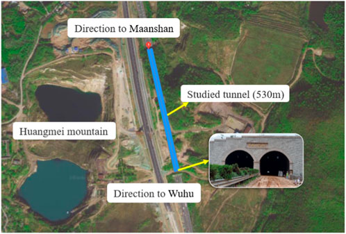
FIGURE 1. Huangmeishan Tunnel location.
The Huangmeishan Tunnel was located at the central part of the southern section of the Ningyan Volcanic Depression in Yangzihuai Terrace. The overlying soil comprised primarily of artificial fill and Quaternary Holocene alluvium. The basement strata mainly consisted of Upper Jurassic Tuff and Yanshanian epidote andesite. The surrounding rock was severely weathered and the rock quality was poor. The main lithology that the tunnel passed is shown in Figure 2. The tunnel area suffered from frequent flooding due to the heavy rainfall and cloudy weather from late June to early July each year.

FIGURE 2. Geological structure of Huangmeishan Tunnel.
According to the research, the horizontal and vertical alignment of the Huangmeishan Tunnel in the initial Nanjing-Wuhu Expressway failed to meet the current standard requirements. The inadequate distance between the tunnel exits and the interchange ramp exit resulted in frequent traffic accidents and heavy congestion within the tunnel. After evaluating various preliminary design options, the decision was made to repurpose the original tunnel into a graben. As a result, it became necessary to demolish the Huangmeishan Tunnel.
The common methods employed in the dismantling of existing tunnels are blasting demolition and mechanical demolition. The schedule for demolition by blasting is relatively short, but the risks are also higher. Meanwhile, the damage caused to tunnel structures by blasting demolition is uncontrollable. Conversely, mechanical demolition requires more time but is more secure. During the demolition process of the Huangmeishan Tunnel, materials such as steel reinforcement and concrete need to be sampled and tested. The rocks in the mountain are highly weathered and loose, which means a high risk of collapse after blasting. On the other hand, the time required for mechanical demolition construction meets the requirements of the overall project schedule. Therefore, the mechanical blasting method was adopted for the Huangmeishan double-arch Tunnel.
The procedure for the mechanical demolition of the Huangmeishan Tunnel was divided into two steps, slope excavation and tunnel demolition. Both the entrance and exit sides were excavated and demolished simultaneously to enhance construction efficiency.
The slope excavation of the Huangmeishan Tunnel was divided into seven levels, and each level was 8 m deep. The slope rate of 1:1 was applied to grades 1 to 6, while a slope rate of 1:1.25 was used for grade 7. A 10 m wide platform was established in the third level slope, while the remaining platforms were 2 m wide. The main lithology of the slope after excavation was diorite-porphyrite with joint and cracks developed, which shown poor rock integrity. These slopes were considered unstable and required enhanced support. The first, second, and seventh graded slopes were reinforced with anchor stock measuring 10 m in length. The other slopes were reinforced with anchor cable measuring 30 m in length (as shown in Figure 3B). The slopes were excavated in layers from top to bottom, and the excavated earth was transported to either the spoil ground or the roadbed area.
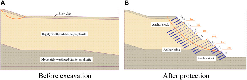
FIGURE 3. The calculation model of the slope before and after excavation and protection. (A) Before excavation. (B) After protection.
In consideration of the climatic conditions specific to the construction area, the rainstorm working condition parameters were employed for the analysis of slope stability. Table 1 presents the values of geotechnical parameters used in this study. The finite element software GEO and the Bishop method were used to investigate the stability of slope excavations and protection. The calculation model of the original slope is given in Figure 3A. The slope reinforcement scheme in the 3.1 section was adopted. The calculation model of the slope after excavation and subsequent protective measures is presented in Figure 3B.
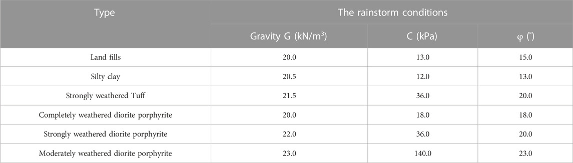
TABLE 1. The values of geotechnical parameters.
The safety coefficient of the slope after excavation and protection is provided in Table 2. Under stormy conditions, all the slope stability factors exceed 1.05, which is the minimum value specified in the slope safety code. As a result, the slope can be generally stable. It can be concluded that the step-by-step excavation and protection measures comply with the code requirements for slope stability.
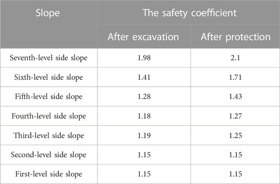
TABLE 2. The safety coefficient of the slope after excavation and protection.
The risks associated with demolishing the tunnel are different from those involved in constructing the tunnel. These risks primarily depend on the quality of the tunnel lining, the demolition scheme and method. In this project, the tunnel was dismantled in sections and the length of every section was 21 m. The mid-partition wall was used as the central axis for construction. The demolition process for the Huangmeishan Tunnel is shown in Figure 4. Initially, the open-cut section of the tunnel was demolished, followed by the section located under the rock. The demolition process for each section was divided into four steps (Figure 5), constructing the construction platform, demolishing the vault, the side-wall, and the remaining part of the tunnel.
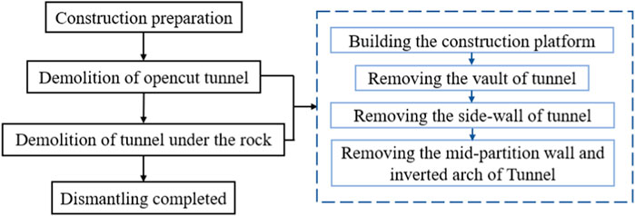
FIGURE 4. The demolition process for Huangmeishan Tunnel.
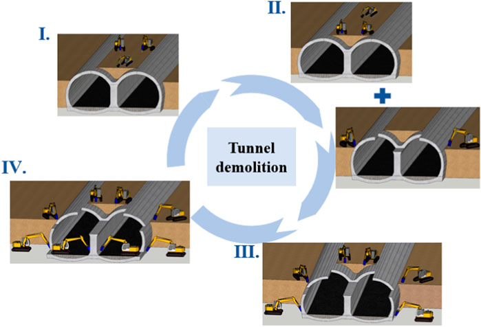
FIGURE 5. The demolition process of each section.
First, the platform for the pickaxe machine was built from the side slope excavation to 5 m away from the tunnel. The excavator removed the soil from the side slope and placed it over the mid-partition wall, creating the platform for the pickaxe machine to carry out the demolition. The width of the soil cover was wider than the combined width of two pickaxes and an excavator, while the thickness of the soil cover was less than the maximum height of the pickaxe construction. The digging machine was positioned at the centerline of the partition wall in the tunnel, with the pickaxe machine located behind it on both sides.
Then, after the platform was constructed, the pickaxe machine proceeded to remove the vault of the tunnel near the mid-partition wall. The slopes on both sides of the open-cut section of the tunnel were excavated by diggers to form steps, and the width of the steps meets the minimum width for safe construction for pickaxe machines. After that, the remaining vault of the open-cut section was demolished.
Next, the sidewall slope was excavated to create steps. The sidewall of the open-cut section of the tunnel was exposed, and promptly removing it.
Finally, the mid-partition wall and the inverted arch in the double-arched tunnel were demolished.
The steps for dismantling the surrounded rock tunnel were identical to those of the open-cut section of the tunnel, but there are a few additional points to consider. When the construction platform was built, the side slopes were excavated vertically until 4.5 m from the tunnel arch, as the length of the tunnel anchors was 4.5 m.
Afterward, they were excavated horizontally. Rocks were left in place above the mid-partition wall to create a platform for the pickaxe machine. Furthermore, if the entire anchor became visible during excavation, a digger was used to level it in the direction of the tunnel axis. If only the anchor head was exposed, the exposed section was cut off.
Due to the specificity and scarcity of this project, research and testing were carried out at the same time as tunnel demolition, including oblique photography, analysis of tunnel defects, material performance tests, and loading tests (as shown in Figure 6). Then, based on the project of Huangmeishan Tunnel, the measures are proposed to prevent similar problems from occurring in other tunnels.
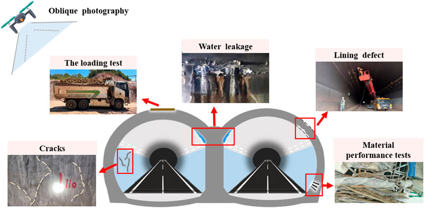
FIGURE 6. Research and testing during the tunnel demolition.
Traditional low-altitude photogrammetry is widely used in many fields such as survey of large areas, security monitoring, disaster emergency response and environmental protection. However, traditional photography is limited to sensors and data processing algorithms. It is difficult to model the realistic construction site because of the lack of sufficient information. In contrast to low-altitude photography, oblique photography collects data from multiple angles. The modeling of oblique photography provides a realistic and comprehensive representation of the ground (Xu et al., 2022; Yang et al., 2022). Additionally, it can help construction managers comprehensively understand the real site information and reduce blind spots in site management (Zhao et al., 2021).
In this project, in order to obtain a detailed and accurate view of the construction scene and track the construction progress in real-time, UAV tilt photography was used to obtain multi-view high-resolution image data. The automatic data processing method was employed to accelerate the generation of detailed 3D models of large scenes. The real demolition process of the tunnel is accurately reconstructed by comparing different 3D models from various angles, as shown in Figure 7.
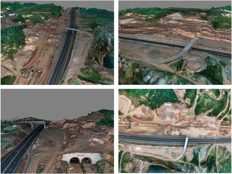
FIGURE 7. The 3D scene of Huangmeishan Tunnel.
During the demolition work, manual recording, and Ground Penetrating Radar (GPR) were used to research the distribution and causes of structural and quality defects in the tunnel, including water leakage, cracks, and lining thickness. The distribution of defects in the tunnels after a long period of operation was revealed, which provided useful data for the development of treatment measures.
Preliminary studies indicated that the Huangmeishan Tunnel was leaking severely and extensively. Figure 8 shows the scene image of water leakage in the Huangmeishan Tunnel. Figure 9 gives the distribution ratio of water leakage area in the tunnel. Figure 10 presents the distribution of water leakage along the tunnel axis.
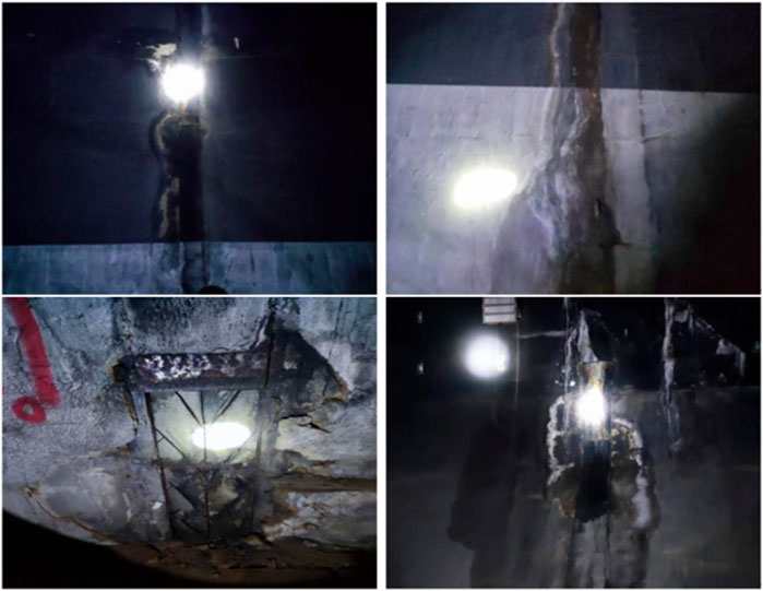
FIGURE 8. The image of water leakage disease in Huangmeishan Tunnel.
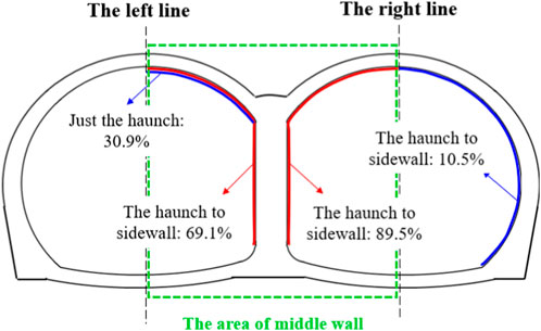
FIGURE 9. The distribution ratio of water leakage area in tunnel.
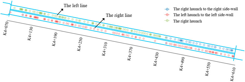
FIGURE 10. The distribution of water leakage along the tunnel axis.
81 instances of water leakage were found in the left line of the Huangmeishan Tunnel, all of which were distributed in the haunch and side wall of the right tunnel. 76 instances of water leakage were found in the right line of the tunnel, with 89.5% of them occurring in the haunch and side wall of the left tunnel. This shows that the water leakage in the partition wall area of Huangmeishan Tunnel is significant. The waterproof design of the mid-partition wall is a key point during the construction of the double-arch tunnel (Shi et al., 2020).
The reasons for this phenomenon are various, such as design factors, construction factors, hydrological factor, and crack diseases. The mid-partition wall of the double-arch tunnel was in the shape of the letter Y. Water seepage within the mountain was collected above the mid-partition wall, resulting in frequent cracking and water leakage. Figure 11 presents the exposed tunnel drainage pipes after the lining structure is removed, which are severely clogged. Clogging of the drainage system was caused by various factors such as concrete leakage during construction, the deposition of crystals from chemical reactions and the degradation the degradation of drainage pipe performance (Zhang et al., 2022).
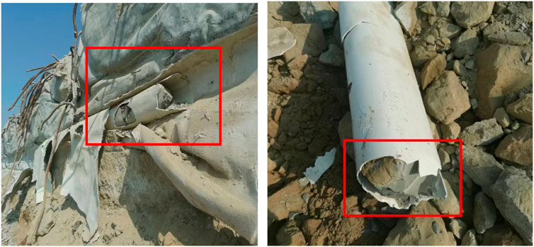
FIGURE 11. The clogged drainpipe in the Huangmeishan Tunnel.
The extent of damage caused by blocked drains was extensive and harmful. The pressure on the support structure increased due to groundwater collecting above the tunnel, potentially leading to cracks in the support structure. A total of 47 cracks were found in the left line of the Huangmeishan Tunnel, with 68.09% of them simultaneously leaking water. Ensuring the quality of tunnel construction is essential to prevent concrete or cement from clogging the drainage system during construction.
Moreover, the geographical location of the Huangmeishan Tunnel inherently facilitates water seepage and leakage. This can be attributed to the tunnel situated in an area that serves as a natural drainage pathway for groundwater. The presence of blockages in the drainage control system within the Huangmeishan Tunnel further exacerbates water leakage.
Therefore, when constructing tunnels in areas with high groundwater levels, new types of drains can be employed to minimize water seepage and leakage issues, such as siphon drains and drains under electromagnetic fields (Zhou et al., 2018). Siphon drainage pipes prevent blockages caused by particle deposits through separating water and soil, and pipes under electromagnetic fields can prevent the formation of crystals.
Figure 12 presents the image of crack disease in Huangmeishan Tunnel. Figure 13 gives the distribution ratio of crack disease in tunnel. Figure 14 shows the distribution of crack disease along the tunnel axis. During the crack disease detection in the Huangmeishan Tunnel, a total of 46 cracks were monitored in the left line. Among these, 1 crack occurred in the left side-wall, 42 cracks occurred from the left side-wall to the right side-wall, and 3 cracks occurred in the right side-wall. In the right line, 13 cracks were monitored, and all of them occurred from the left side-wall to the right side-wall.
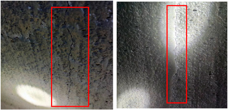
FIGURE 12. The image of crack disease in Huangmeishan Tunnel.
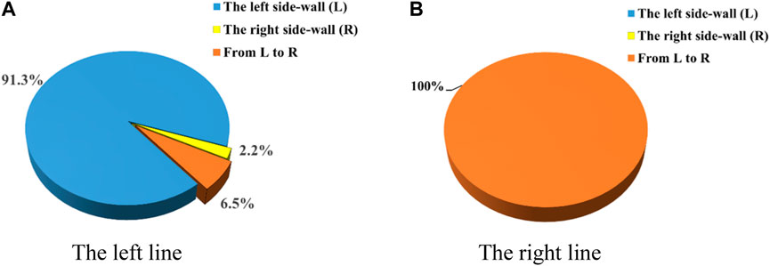
FIGURE 13. The distribution ratio of crack disease in tunnel. (A) The left line. (B) The right line.
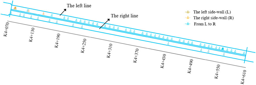
FIGURE 14. The distribution of crack disease along the tunnel axis.
Most cracks have a length of less than 10 m and a width of less than 1 mm. The widest crack detected was found at section YK4+576, measuring 15 mm in width (as shown in Figure 15). It is worth noting that all the existing cracks in the Huangmeishan Tunnel were caused by construction joints.
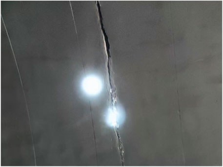
FIGURE 15. Crack at section YK4+576.
Tunnel cracks may be caused by water leakage. Take the left line as an example, 32 cracks were found to be leaking water, accounting for 68.09% of the crack issues and 39.51% of the water leakage issues. The clogging of the tunnel drainage system accelerated the formation of sediments in the water. The lining was subjected to prolonged periods of pressure from sediment and water, resulting in lining leakage and cracking disease.
Additionally, the external loads associated with the dismantling process were also a reason for cracking diseases. The stability of the rock beneath the Huangmeishan Tunnel was poor. Above the entrance to the tunnel is a road for heavy vehicles, and Figure 14 shows concentrated cracks on the left and right side-walls of the entrance lining. It can be inferred that the cracks at the portal are caused by external loads.
The results of the thickness detection for the lining concrete by GPR at the entrance of Huangmeishan Tunnel are presented in Figure 16. The distribution of insufficient thickness in the second lining along the axis of the Huangmeishan Tunnel is shown in Figure 17. A total of 1,012 records were collected from the left line, with 113 records (11.17%) falling below the design thickness of the lining. Among them, 92 data had a thickness lower than the design value within 5 cm, accounting for 9.09% of the total. Additionally, 20 data were lower than the design value of the second lining between 5 cm and 10 cm, accounting for 1.98%, and 1 data was lower than the design value by more than 10 cm, accounting for 0.10%.
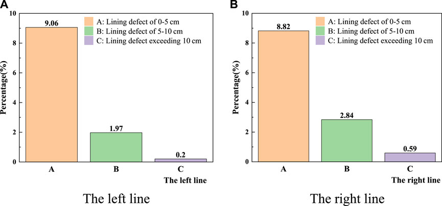
FIGURE 16. The percentage of insufficient lining thickness at the entrance of Huangmeishan Tunnel. (A) The left line. (B) The right line.
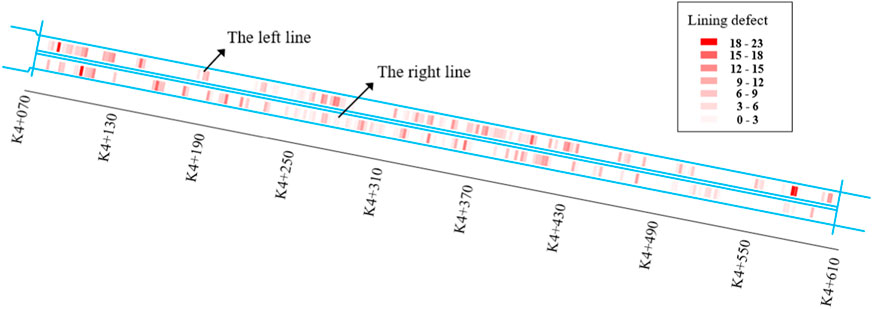
FIGURE 17. Distribution of insufficient thickness of the second lining along the axis of Huangmeishan Tunnel.
Similarly, 1,020 records were collected from the right line, with 125 records (12.25%) falling below the design thickness of the lining. Among them, 90 data had a thickness lower than the design value within 5 cm, accounting for 8.82% of the total. 29 data were lower than the design value between 5 cm and 10 cm, accounting for 2.84%, and 6 data were lower than the design value by more than 10 cm, accounting for 0.59%.
These results indicate that the thickness of the secondary lining in the Huangmeishan Tunnel fails to meet the requirements. Several factors may have contributed to this issue, including poor construction methods, limited construction monitoring, and inexperienced workers (Lu et al., 2019). Insufficient excavation during tunnel construction and untimely construction of the secondary lining may result in lining defects. This untimely construction could lead to significant deformations in the lining, and the inner contour of the primary lining exceeding the expected contour (Lu et al., 2021; Jiang et al., 2023). Inadequate thickness of the lining can cause stress redistribution, reducing the stiffness of the lining and increasing the risk of collapse (Liu et al., 2020).
The concrete rebound hammer was employed for assessing the compressive strength of the secondary lining concrete in the Huangmeishan Tunnel. The design strength for both the sprayed concrete and the secondary lining concrete of Huangmeishan Tunnel was 25 MPa. However, the average of the 48 test results was 50.27 MPa, and all test results exceeded the design value.
The distribution of concrete compressive strength along the tunnel axis is shown in Figure 18. The minimum values of concrete compressive strength often occur at the tunnel entrances or at the deepest part of the tunnel. This is primarily due to the susceptibility of the entrance section to environmental erosion, leading to degradation of the structural performance. Additionally, the tunnel structure at the deepest burial depth was subjected to significant loads, which resulted in the degeneration of the mechanical property of the concrete.
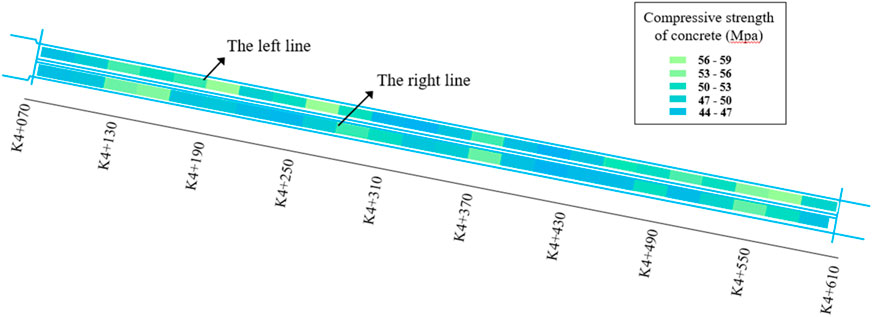
FIGURE 18. The distribution of concrete compressive strength along the tunnel axis.
Besides, the rebars were sampled and tested during the demolition of the tunnel. The bars were sampled every 50 m, and the length of the samples was more than 50 cm. 11 bars were sampled from mileage K4+125∼K4+575 on the right line, 7 bars were sampled from mileage ZK4+125∼ZK4+575 on the left line, and 6 bars were sampled from mileage 190–550 on the mid-partition wall. The average test results of 23 rebar samples are shown in Table 3. The average corrosion rate of the rebar samples is 45.2%, and the average tensile strength is 556.9 MPa. There is no significant correlation between the yield strength and the sampling location or corrosion rate.
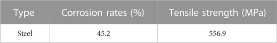
TABLE 3. The average test results of rebar samples.
The tunnel loading test is a method used to assess the strength and stability of a tunnel structure. It provides valuable information about the structural performance by monitoring the response of the structure under load. Conducting an on-site tunnel loading test before the demolition of an existing tunnel is necessary to identify the strength and stability of the tunnel structures under actual load conditions. The tunnel loading test is an important tool for ensuring the safety and reliability of underground infrastructure. It is widely used in tunnel engineering and construction projects around the world.
The demolition of the Huangmeishan Tunnel involved the complete excavation of the mountain above the tunnel, and the tunnel vault will be used as a traffic lane for heavy vehicles. The safety of traffic under shallow overburden conditions needs to be verified in advance. Therefore, a loading test of the tunnel was conducted.
During the tunnel demolition, a construction transport vehicle with a weight of 40 tons (when fully loaded) was used. A fully loaded truck is the maximum load for tunnel dismantling. Hence, a 40-ton load test was carried out at section ZK4+512 in the Huangmeishan Tunnel. The subsidence at the vault and the haunch was simultaneously monitored. Figure 19 presents the time curves of the vertical displacement at the vault and the haunch at section ZK4+512. The maximum vertical displacement of the tunnel arch and haunch after the loading test was determined to be 1.73 mm and 1.32mm, respectively. These findings indicate that the construction vehicles were able to safely move above the tunnel during the study, confirming the reasonableness of the demolition construction scheme.
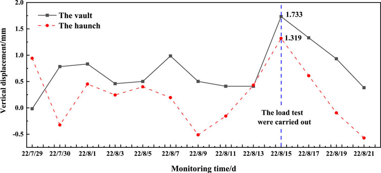
FIGURE 19. The time curves of the vertical displacement at the vault and the haunch at section ZK4+512.
According to the quality defects and deterioration detection of the Huangmeishan Tunnel, the main problems of the Huangmeishan Tunnel after a long period of service are water seepage, cracks, and insufficient thickness of the second lining. Water leakage in the tunnel may cause damage to the concrete structure of the tunnel lining and reduce the performance of the lining in enclosing the tunnel rock. Localized thickness deficiencies of the tunnel lining may result in cracks defects. The bending moment at the tunnel lining with localized thickness deficiencies will be reduced, but the bending moment of the adjacent lining would be increased. Insufficient thickness of the tunnel lining will directly lead to the reduction of the bearing capacity of the tunnel lining structure. When the insufficient thickness of the tunnel lining is more serious, the tunnel lining may even fracture, collapse, and result in other catastrophic consequences that significantly impact the safety of the lining.
Therefore, during the dismantling process of the Huangmeishan Tunnel, heavy trucks were restricted from passing through sections where thickness defects and cracks were found. Concurrently, enhanced monitoring of convergence deformations around the tunnel entrance was implemented to mitigate safety risks, such as collapses and other potential accidents.
Based on the case of the Huangmeishan Tunnel demolition project, this section aims to analyze the reasons and propose measures to prevent similar issues from appearing in the design, construction, and operation phases of other tunnels.
When designing a tunnel, there are limitations on the quantity and depth of investigation and design work. These limitations may prevent the acquisition of complete geological data. For example, factors such as inaccurate classifications of surrounding rock, insufficient understanding of the direction of rock layers, and unclear identifications of geological sections may lead to the lack of specificity during the design. Thus, it is imperative to implement the following measures.
Some advanced techniques and technologies such as ground penetrating radar and seismic surveys, could be employed to obtain a more comprehensive understanding of the subsurface conditions (Yun et al., 2018). The selection of an appropriate tunnel cross-section structure should be based on the specific geological conditions. Additionally, close attention must be paid to the construction site, enabling timely design modifications in response to the actual construction processes and geological conditions encountered.
To mitigate the risk of structural damage, it is recommended to employ a foundation structure for the tunnel arch foot featuring a straight outer side and a rounded inner side. This design configuration helps to distribute stress and prevent concentration, reducing the likelihood of cracking in both the arch foot and the sidewalls.
In tunnel construction, common construction quality problems are often related to the initial support, the arch, drainage systems, and secondary lining construction processes. To address these issues, the following measures can be implemented.
To optimize the surface blasting effects, the drilling efficiency and precision are suggested to be improved. Specialized tools are employed to enhance the quality of the drainage system, such as an infrared scanning position system, ultrasonic welding, and longitudinal and circumferential water-stops. The flow and quality of concrete for the secondary lining are controlled by employing the window pouring technology. The arch mold grouting construction technique is utilized to minimize hollowing and insufficient thickness of the lining.
Different widths of cracks require different treatment methods. The assessment of cracking is needed as it can be a serious structural issue and risk life. For cracks that do not jeopardize structural safety, Table 4 suggests the recommended treatment methods for cracks of different widths.

TABLE 4. The treatment methods for cracks of different widths.
In the treatment of water seepage, instant sealants and high-performance waterproofing agents are used for direct sealing. A 1–2 mm thick cement-based penetrating crystalline waterproofing material is applied within a minimum range of 40 cm around the water seepage point. The treatment method for water leakage defects is correlated with the location of the leakage. Table 5 provides the treatment methods for different locations of water leakage.
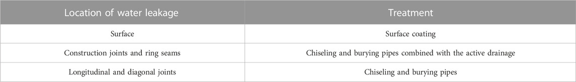
TABLE 5. The treatment methods for different locations of water leakage.
Based on the demolition project of the Huangmeishan Tunnel, the current paper proposed a demolition scheme for the double-arch tunnel and presented various researches during the demolition. The safety of the Huangmeishan Tunnel structure can be guaranteed after a long period of operation. The conclusions were as follows:
(1) Mechanical excavation was used in this project to demolish the tunnel and the slope stability was analyzed. The demolition scheme of the double-arch tunnel was proposed, including building the construction platform, demolishing the vault, the side-wall, and the remaining part of the tunnel.
(2) Oblique photography combined with automated modeling provides a more comprehensive view of the construction site and surrounding environment. This was confirmed in the Huangmeishan demolition project.
(3) Tunnel dismantling found that most of the leakage damage was distributed by the mid-partition wall, and the drain pipes were clogged severely by cement. Most of the tunnel lining thickness defects were within 5 cm. In the material performance tests, the actual compressive strength of the concrete was 50.07Mpa and the average corrosion rate of the rebar was 45.2%.
(4) The largest displacements of the tunnel arch and haunch after the loading test were 1.73 mm and 1.32 mm respectively, which show that heavy vehicle traffic during tunnel dismantling is safe. The loading test is necessary in tunnel demolition project.
(5) Based on the results of the research, this paper presents recommendations for the lifecycle of similar tunnels. Besides, this study could provide a reference for similar demolition projects, and the results of the research could be applied in future work, such as the development of an evaluation model for the structural behavior of long-term service tunnels.
The original contributions presented in the study are included in the article/Supplementary Material, further inquiries can be directed to the corresponding author.
XK: Writing–original draft. XL: Project administration, Writing–review and editing. JX: Funding acquisition, Project administration, Writing–review and editing. AR: Data curation, Writing–review and editing. TL: Data curation, Writing–review and editing. YR: Writing–review and editing.
The authors declare financial support was received for the research, authorship, and/or publication of this article. Anhui provincial communications Holding Group science and technology project (JKKJ-2021-22).
Author JX was employed by Anhui Transportation Holding Group Co., Ltd.
The remaining authors declare that the research was conducted in the absence of any commercial or financial relationships that could be construed as a potential conflict of interest.
The authors declare that this study received funding from Anhui provincial communications Holding Group science and technology project (JKKJ-2021-22). The funder had the following involvement in the study: provide data and participate in field trials.
All claims expressed in this article are solely those of the authors and do not necessarily represent those of their affiliated organizations, or those of the publisher, the editors and the reviewers. Any product that may be evaluated in this article, or claim that may be made by its manufacturer, is not guaranteed or endorsed by the publisher.
Bai, Y., Li, X., Yang, W., Xu, Z., and Lv, M. (2022). Multiscale analysis of tunnel surrounding rock disturbance: a PFC3D-FLAC3D coupling algorithm with the overlapping domain method. Comput. geotechnics 147, 104752. doi:10.1016/j.compgeo.2022.104752
Bowers, K., and Moss, N. (2018). Investigation and reconstruction of a London Underground tunnel, UK. Proc. Institution Civ. Eng. - Civ. Eng. 171 (1), 43–48. doi:10.1680/jcien.17.00019
Chang, L., Zhang, D., and Zhang, S. (2021). Characteristics and treatment measures of lining damage: a case study on a mountain tunnel. Eng. Fail. Anal. 128, 105595. doi:10.1016/j.engfailanal.2021.105595
Chen, Z., Chen, J., Liu, H., and Zhang, Z. (2018). Present status and development trends of underground space in Chinese cities: evaluation and analysis. Tunn. Undergr. Space Technol. 71, 253–270. doi:10.1016/j.tust.2017.08.027
Ciro, C., and Isidoro, R. (2022). A 3D computational fluid dynamics model for assessing the concrete spalling of a tunnel lining in the event of a fire. Comput. geotechnics 152, 527–540. doi:10.1016/j.compgeo.2022.105041
Ding, L., Zhang, L., Wu, X., Skibniewski, M. J., and Qunzhou, Y. (2014). Safety management in tunnel construction: case study of Wuhan metro construction in China. Saf. Sci. 62, 8–15. doi:10.1016/j.ssci.2013.07.021
Ding, Y., Zhang, X., and Zhang, B. (2022). Preliminary study on double lining support design for water plugging of highway tunnel under high water pressure in mountain area based on limited drainage. Appl. Sci. 12 (15), 7905. doi:10.3390/app12157905
Eisch, J. E. (1983). Planning/design features and case studies in freeway reconstruction. PART I. Inst. Transp. Eng. J. 10 (53), 14–23.
Gianpiero, B. (2020). Astra-Tunnelerneuerungsmethode – erneuerung einer nicht armierten Innenschale in Nachtarbeit bei Gewährleistung des Betriebs aller Fahrstreifen in Spitzenzeiten. Geomechanics Tunn. 13, 547–556. doi:10.1002/geot.202000024
GongHe, C. X., Li, Y., He, S. Z., Cheng, X., Huang, L. Y., et al. (2017). Long-term field corrosion monitoring in supporting structures of China xiamen xiangan subsea tunnel. Acta Metall. Sin. Lett. 30 (004), 399–408. doi:10.1007/s40195-017-0552-0
Han, F., Liu, Z., Wang, Yi, et al. (2022). Influence of road tunnel transforming to cutting on safety of lining structure. J. Chongqing Jiaot. Univ. Nat. Sci. 41 (7), 104–112. doi:10.3969/1.155n1674-0696.2022.07.16
Hawley, C. J., and Gräbe, P. J. (2022). Water leakage mapping in concrete railway tunnels using LiDAR generated point clouds. Constr. Build. Mater. 361, 129644. doi:10.1016/j.conbuildmat.2022.129644
Höllrigl Michael, , Josef, T., and Wanker, C. (2015). Tunneling under challenging conditions – general renovation, escape and safety passageways via the supply air duct at the. Arlb. Road. Tunnel". 10, 7–10.
Jia, Y., Xia, Y., Chen, X., Zhou, Y., Han, X., and Zhou, S. (2019). Force and deformation characteristics during the reconstruction and expansion of shallow single-tube tunnels into large-span multiarch tunnels. Adv. Mater. Sci. Eng. 2019, 1–13. doi:10.1155/2019/2783784
Jiang, Xi, Zhang, X., Wang, S., Yun, B., and Huang, B. (2022). Case study of the largest concrete earth pressure balance pipe-jacking project in the world. Transp. Res. Rec. 2676 (7), 92–105. doi:10.1177/03611981221076842
Jiang, Xi, Zhang, Y., Zhang, Z., and Bai, Y. (2021). Study on risks and countermeasures of shallow biogas during construction of metro tunnels by shield boring machine. Transp. Res. Rec. 2675 (7), 105–116. doi:10.1177/0361198121994594
Jiang, Xi, Zhu, H., Yan, Z., Zhang, F., Ye, F., Li, P., et al. (2023). A state-of-art review on development and progress of backfill grouting materials for shield tunneling. Dev. Built Environ. 16, 100250. doi:10.1016/j.dibe.2023.100250
Kiwamu, T., and Kiyoshi, K. (2020). Evaluation of spalling of concrete pieces from tunnel lining employing joint shear model. Tunn. Undergr. Space Technol. 103, 103456. doi:10.1016/j.tust.2020.103456
Lin, J. (2014). Existing operational railway tunnel water leakage causes and remediation technologies. Adv. Mater. Res. 1004-1005, 1444–1449. doi:10.4028/www.scientific.net/amr.1004-1005.1444
Liu, S., Yao, S., Sun, R., and Yang, J. (2020). Damage behavior and maintenance design of tunnel lining based on numerical evaluation. Eng. Fail. Anal. 109, 104209. doi:10.1016/j.engfailanal.2019.104209
Lu, P., Chen, C., Liao, C. C., et al. (2019). Model test on joint leakage in underwater shield tunnel. Chin. J. Rock Mech. Eng. 38 (5), 993–1004.
Lu, P., Qiao, D., Wu, C., Wang, S., He, X., Zhang, W., et al. (2021). Effect of defects and remediation measures on the internal forces caused by a local thickness reduction in the tunnel lining. Undergr. Space 1 (7), 94–105. doi:10.1016/j.undsp.2021.06.001
Lunardi, P. (2012). Widening the Nazzano motorway tunnel from two to three lanes + an emergency lane without interrupting traffic. Avances Tecnol´ ogicos Einnovaci´3, 894–905.
Mei, W., Zhou, Y., and Hou, J. (2010). Real-time georobot automatic monitoring during shield under-crossing existing tunnel[C]. Int. Conf. Optoelectron. Image Process. 11, 153–156. doi:10.1109/ICOIP.2010.237
Shi, J., Zhang, X., Liang, J., Hu, L., and Li, Z. (2020). Study on multi-arch tunnel leakage disease with influence of rainfall and groundwater change. IOP Conf. Ser. Mater. Sci. Eng. 741 (1), 012101. doi:10.1088/1757-899x/741/1/012101
Tang, L., Yu, Li, Luo, X., Zhou, J., Li, Z., Yang, H., et al. (2023). Shaking table test on the seismic response and reinforcement measures of double-arch tunnels in mountainous areas. Tunn. Undergr. space Technol. 2023 (139), 105232. doi:10.1016/j.tust.2023.105232
Wang, C., Zhang, M., and He, Y. (2015). Deformation calculation for the existing tunnel induced by undercrossing shield tunneling. Int. J. Res. Eng. Sci. 11 (3), 07–11.
Wang, S., Jiang, Xi, and Bai, Y. (2019). The influence of hand hole on the ultimate strength and crack pattern of shield tunnel segment joints by scaled model test. Front. Struct. Civ. Eng. 13 (13), 1200–1213. doi:10.1007/s11709-019-0546-2
Wang, Y., Li, J., Wang, Z. F., and Chang, H. (2022). Structural failures and geohazards caused by mountain tunnel construction in fault zone and its treatment measures: a case study in Shaanxi. Eng. Fail. Anal. 138 (4), 106386. doi:10.1016/j.engfailanal.2022.106386
Wu, B., Liu, W., Shi, P., Xu, X., and Liu, Y. (2022). A case study of newly tunnels over-crossing the existing subway tunnels. Int. J. Distributed Sens. Netw. 18 (3), 155013292210871–176. doi:10.1177/15501329221087183
Xu, N., Zhang, X., and Zhao, J. L. (2022). Study on construction technology of bridge structure based on oblique photography. J. Phys. Conf. Ser. 2158 (1), 012024. doi:10.1088/1742-6596/2158/1/012024
Yan, F., Qiu, W., Zheng, Y., Jiang, S., Hu, H., Gao, G. g., et al. (2021). Experimental investigation and numerical analysis of mechanical behaviour of railway station reconstruction over twin tunnels. Tunn. Undergr. Space Technol. 112, 103918. doi:10.1016/j.tust.2021.103918
Yang, B., Ali, F., Zhou, Bo, Li, S., Yu, Y., Yang, T., et al. (2022). A novel approach of efficient 3D reconstruction for real scene using unmanned aerial vehicle oblique photogrammetry with five cameras. Comput. Electr. Eng. 99, 107804. doi:10.1016/j.compeleceng.2022.107804
Yang, J., Chen, L., Chen, Q., and Xie, X. (2017). Performance of overlapped shield tunneling through an integrated physical model tests, numerical simulations and real-time field monitoring. Undergr. Space 2 (1), 45–59. doi:10.1016/j.undsp.2017.04.002
Yike, W., and Yu, L. (2021). Analysis of detection and treatment schemes of highway tunnel lining cracks. J. Archit. Res. Dev. 5 (1), 4–7. doi:10.26689/jard.v5i1.1820
Yun, B., Jiang, Xi, Diaz, D., et al. (2018). “TBMs: capabilities, limitations and challenges,” in Proceedings of GeoShanghai 2018 International Conference: Tunnelling and Underground Construction, Shanghai, China, May, 2018, 528–535. doi:10.1007/978-981-13-0017-2_53
Zhang, S., Xu, Q., Yoo, C., Min, B., Liu, C., Guan, X., et al. (2022). Lining cracking mechanism of old highway tunnels caused by drainage system deterioration: a case study of Liwaiao Tunnel, Ningbo, China. Eng. Fail. Anal. 137, 106270. doi:10.1016/j.engfailanal.2022.106270
Zhang, X., Yu, J., et al. (2020). Mountain tunnel under earthquake force: a review of possible causes of damages and restoration methods. J. Rock Mech. Geotechnical Eng. 12 (02), 206–218. doi:10.1016/j.jrmge.2019.11.002
Zhao, S., Kang, F., Li, J., and Ma, C. (2021). Structural health monitoring and inspection of dams based on UAV photogrammetry with image 3D reconstruction. , Automation Constr. 130, 103832. doi:10.1016/j.autcon.2021.103832
Zheng, Y. (2023). Deep excavation technique for demolition and reconstruction of the existing jinji pass tunnel. Subgr. Eng. 2023 (01), 212–215. doi:10.13379/j.issn.1003-8825.202211040
Zhou, Y., Zhang, X., Wei, L., Liu, S., Zhang, B., and Zhou, C. (2018). Experimental study on prevention of calcium carbonate crystallizing in drainage pipe of tunnel engineering. Adv. Civ. Eng. 2018, 1–11. doi:10.1155/2018/9430517
Keywords: tunnel demolition, water leakage, cracks, lining thickness, loading test
Citation: Kou X, Li X, Xie J, Rusuli A, Li T and Rui Y (2023) Research on the dismantling of double-arch tunnel after long-term service—the case study of Huangmeishan Tunnel demolition project. Front. Earth Sci. 11:1296818. doi: 10.3389/feart.2023.1296818
Received: 19 September 2023; Accepted: 23 October 2023;
Published: 08 November 2023.
Edited by:
Jianyong Han, Shandong Jianzhu University, ChinaReviewed by:
Jun Wu, Shanghai Normal University, ChinaCopyright © 2023 Kou, Li, Xie, Rusuli, Li and Rui. This is an open-access article distributed under the terms of the Creative Commons Attribution License (CC BY). The use, distribution or reproduction in other forums is permitted, provided the original author(s) and the copyright owner(s) are credited and that the original publication in this journal is cited, in accordance with accepted academic practice. No use, distribution or reproduction is permitted which does not comply with these terms.
*Correspondence: Yi Rui, cnVpeWlAdG9uZ2ppLmVkdS5jbg==
Disclaimer: All claims expressed in this article are solely those of the authors and do not necessarily represent those of their affiliated organizations, or those of the publisher, the editors and the reviewers. Any product that may be evaluated in this article or claim that may be made by its manufacturer is not guaranteed or endorsed by the publisher.
Research integrity at Frontiers
Learn more about the work of our research integrity team to safeguard the quality of each article we publish.