 Bin Li1
 Zhaorui Lin
 Haibin Ding
- 1China Railway Construction Group Co., Ltd., Beijing, China
- 2Institute of Geotechnical Engineering, School of Civil Engineering and Architecture, East China Jiaotong University, Nanchang, Jiangxi, China
- 3State Key Laboratory of Performance MonitoringProtecting of Rail Transit Infrastructure, East China Jiaotong University, Nanchang, Jiangxi, China
Due to the extensive karst development zone in karst areas, the stability of the underground soil layer is poor. The support of foundation pits in this area will be affected by complex environmental factors, and if not handled properly, it will cause significant safety hazards and economic losses. In this paper, the three-dimensional finite element model of the complex foundation pit and adjacent foundation pit group was established with the help of Midas GTS NX numerical software, and numerical simulation was carried out for the whole foundation pit excavation and construction process, and the deformation results of the adjacent foundation pit support structure of the complex foundation pit group and the soil outside the foundation pit were obtained. The results show that the underground wall of the complex foundation pit shifted to the north under the action of buttresses, with a similar “cantilever” displacement pattern on the south side of the underground wall in the center, a “push-back displacement” on the north side of the underground wall in the center, and a “ventral” displacement pattern at the corners of the grounded wall and on the east and west sides. Combined with the field measurement data, the support piles in the internal support system have a “cantilever” displacement pattern under the condition of massive soil unloading in the vicinity of the foundation pit, while the supporting piles show a “parabolic” displacement pattern under the action of the corner internal support. The deformation characteristics of the foundation pit in the presence of adjacent pits are significantly different from the results based on empirical laws. The results of the above study will provide useful technical guidance for the safety of excavation support for foundation pit groups in complex environments and the reasonable control of the surrounding environment.
1 Introduction
Due to the extensive karst development zone in karst areas, the stability of the underground soil layer is poor. The support of foundation pits in this area will be affected by complex environmental factors, and if not handled properly, it will cause significant safety hazards and economic losses (Liu et al., 2011; Liu and Li, 2023; Tan and Li, 2011).
Typical profiles in a foundation pit are frequently taken and calculated using methods such as the equivalent beam method or the elastic foundation beam method in traditional pit design theory. Many researchers have expanded and extracted typical profiles containing the foundation pit and the surrounding environment on this basis. A representative theoretical model is formed by simplifying these complex operating conditions, which can then be designed or theoretically derived (Chen et al., 2023; Liu et al., 2019; Liu et al., 2023a; Shouhua et al., 2019; Xu et al., 2013a; Xu et al., 2013b; Xu et al., 2022). These works have a guiding significance for the foundation pit design. These theoretical results, however, frequently fail to consider the impact of foundation pit construction on the surrounding environment. Hsieh and Ou (Pio-Go and Chang-Yu, 1998) proposed the “concave settlement profile” and “spandrel-type settlement profile” soil settlement models and applied them to the prediction calculation of foundation excavation on the environment outside the pit. Many researchers have praised the findings of their studies. Based on their findings, additional theoretical models have been promoted and developed to deal with more complex geological conditions and to improve working conditions (Chen et al., 2022; Dan and Sahu, 2012; Fan et al., 2021; Gao et al., 2023; NG et al., 2012; Ou and Hsieh, 2011; Son and Cording, 2011; Zhang et al., 2023). These calculation models typically only consider soil deformation, and the conditions of adjacent structures are not fully explored.
Some cases of damage to surrounding structures caused by foundation excavation (Li et al., 2023; Shen et al., 2023; Zhang and Wu, 2014; Zhang et al., 2018) highlight the need for monitoring and specific consideration of deep foundation pits with complex surroundings in practical engineering. Deformation monitoring of foundation pits, as an important means of preventing and controlling foundation pit construction risks, plays a critical role in avoiding foundation pit accidents. Tan and Wei (2012) conducted monitoring for narrow-shaped foundation pits in soft soil areas. Their findings highlighted the importance of the bottom slab in preventing pit deformation in soft soil areas. Scholars have also emphasized the importance of monitoring the surrounding environment (Liu et al., 2020; Song et al., 2020); however, monitoring after the engineering begins is insufficient, and the lack of effective prediction of deformation may result in delays and material waste. Numerical simulation methods are frequently used in engineering projects that are difficult to predict using traditional theories. The case discussed by Guo et al. (Guo et al., 2019) is influenced by three adjacent buildings and the river, and the “T” excavation with varying depths adds to the project’s complexity. In this case, the finite difference method was used to provide effective support for project execution and risk assessment. In this type of analysis work, the finite element method is also widely used. These studies provide a foundation for the protection of existing structures such as subway tunnels (Ye et al., 2021), buildings (Dong et al., 2016; Liu et al., 2023b; Mangushev et al., 2016), and adjacent pile foundations (Zhang et al., 2021). Furthermore, some researchers have established procedures for assessing and predicting possible deformation of foundation pits based on mathematical frameworks such as probabilistic models, using monitoring data from previous projects and numerical simulation results (Juang et al., 2011; Schuster et al., 2009; Wang et al., 2014; Yan et al., 2023a). Unfortunately, due to the complexities of soil properties, these works are difficult to apply in a wide range of geological conditions.
In recent years, the simultaneous construction of groups of foundation pits has been reported in the literature in the context of urban land constraints (Li, 2021; Yan et al., 2023b; Zeng et al., 2018). Because of the proximity of a large amount of soil unloading, this construction situation has a stronger specificity as a special case of the interaction between the foundation pit and the surrounding environment. The complicated surrounding environment complicates foundation pit deformation prediction work. At the same time, the narrow working surface caused by the foundation pit’s proximity, as well as the coordination of work between different units in charge of the pit, pose serious challenges to the monitoring work performed in the foundation pit.
This paper is based on the foundation pit of the Guangzhou Baiyun Station Project’s production and living complex building, as well as the complex construction environment formed by this foundation pit and the three deep foundation pits surrounding it. The 3D finite element software Midas GTS NX is used to simulate the mutual position relationship between the four foundation pits and establish the 3D finite element model. The influence of foundation pit construction on the adjacent foundation pit and the surrounding soil is studied by construction simulation, which ensures safety and stability in the construction process. Meanwhile, the deformation of the supporting structure under the influence of excavation and adjacent foundation pit is monitored by laying inclined pipes around the representative positions of the foundation pit of the production and living complex building. The security problems in the project are effectively found in the simulation and monitoring, which ensures the availability of the support structure and the sustainability of the project. The development of the foundation pit and the reasonable control of its surrounding deformation are summarized qualitatively, which provides the necessary experience for the stable design, construction, and research of similar projects.
2 Project overview
The new Guangzhou Baiyun Station integrated transportation hub building, with a total scale of approximately 453,000 square meters, is located in the south of Baiyun District, Guangzhou City. One of the most complicated surrounding environments and the most diverse support forms in the new Baiyun Station project is the basement pit group of the production and living complex building (Figure 1). Baiyun District of Guangzhou belongs to karst landform, and the area where the foundation pit of production and living buildings is located contains a complex environment such as karst. The complex surrounding environment makes it necessary to analyze the sustainability of the pit to ensure that the project is safe and sustainable and that the adjacent buildings are adequately secured. The top view of the construction site in Figure 2 depicts the complex environment surrounding the project site. The foundation pit is a three-story basement pit of the production and living complex building, with an outer border of a regular rectangle 110.2 m from north to south and 83.0 m from east to west. The perimeter is approximately 386.4 m, with an area of approximately 9,146.6 m2. Furthermore, the south side of the first floor is partially wedge-shaped pick-out, with an area of approximately 769.3 m2. The foundation pit is surrounded by a railway station house foundation pit (hereinafter referred to as the station house foundation pit), a tourist bus foundation pit (hereinafter referred to as the bus foundation pit), and a subway reserved transfer channel foundation pit (hereinafter referred to as the transfer channel foundation pit), and the surrounding environment is very complicated, so the mutual influence between foundation pit excavation and the surrounding environment must be considered. The pit’s north side is adjacent to the bus pit (excavation depth 17.90 m), and the distance between the two pit support structures is approximately 9.04 m. The east side of the pit is adjacent to the station house pit (excavation depth 14.40 m), with a distance of about 8.97 m between the two pit support structures. The transfer channel pit is adjacent to the west side of the pit (excavation depth 10.20 m), and the distance between the two pit support structures is approximately 7.21 m. Numerical simulation studies are necessary to ensure that deformation is effectively controlled during foundation pit construction, to avoid affecting the construction of adjacent pits and the use of existing structures, and to improve construction safety and sustainability.
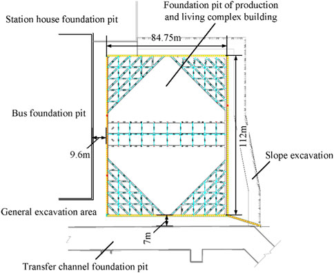
FIGURE 1. Foundation pit plan.

FIGURE 2. Top view of the construction site.
The production and living complex’s foundation pit uses a comprehensive support system that combines slope release, grouting pile, and internal support. The ground connection wall supports the adjacent bus foundation pit and station house foundation pit, while the interchange channel foundation pit is supported by the ground connection wall and internal support. The three adjacent foundation pits all finished the support structure construction before the production and living complex foundation pit, with the underground main structure of the bus foundation pit and station house foundation pit being completed during the excavation and support of the production and living complex foundation pit.
3 Finite element simulation
3.1 Selection of typical profiles and determination of model calculation parameters
According to pertinent drilling data and ground investigation findings, the typical section is depicted in Figure 3. In this paper, the soil distribution in the foundation pit area of the production and living complex is represented by the number. Miscellaneous fill, silty silt-powdered clay, powdery clay, fully weathered marl, and moderately weathered marl are the principal soil layers that extend from the ground to the impact area under consideration. Based on the elevation displayed in the soil profile, it is possible to calculate the thickness of each layer. Table 1 provides an overview of the soil parameters for each layer that were discovered through field and laboratory tests.
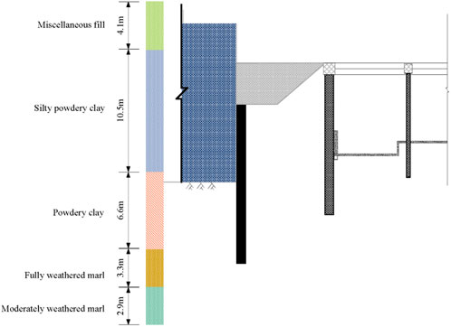
FIGURE 3. Typical soil profile.
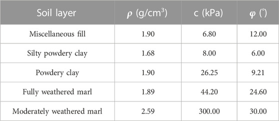
TABLE 1. Parameters of each soil layer.
3.2 Establishment of finite element model
The length, width, and thickness of the three-dimensional finite element model in this paper are 340 m, 160 m, and 50 m respectively, and they are created using the finite element software Midas GTS NX in accordance with the actual engineering situation (Figure 4). The model is surrounded by simulations of the existing transfer channel pit, bus pit, and station house pit. Applied surface loads are used to simulate the loads brought on by above-ground structures.
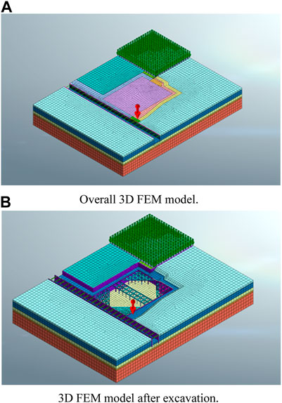
FIGURE 4. 3D FEM model. (A) Overall 3D FEM model. (B) 3D FEM model after excavation.
The adoption of an appropriate soil ontological model for simulation is essential for the application of the finite element model. The modified Moore-Coulomb model is employed to simulate the stress-strain behavior of the soil from the standpoint of satisfying engineering requirements and convenience. To simulate the ground link wall and bored bite pile, the model uses a 2D plate unit. According to the actual working conditions, a bored bite pile with a pile diameter of 1,000 mm and a ground link wall with a thickness of 800 and 1,000 mm are set, respectively. The stiffness equivalence principle then converts the bite pile’s thickness to the cross-sectional thickness of the plate. The internal support, crown beam, and lattice column were each simulated using a 1D beam unit, with model parameters set by the actual size of the construction site. The underground bus station and station house structures were modeled using solid units.
3.3 Construction process simulation
The project used in this paper required 150 days to complete, starting with the boring of the occluded piles and ending with the excavation of the foundation pit. The corresponding construction steps were set up by the construction progress plan, as shown in Table 2, to accurately simulate the actual situation. The slope release excavation for steps 2 and 4 was completed in two steps, and the fill between the pits for the production and living complex, the bus, and the interchange channel was also excavated and leveled in accordance with the excavation elevation in these two steps.
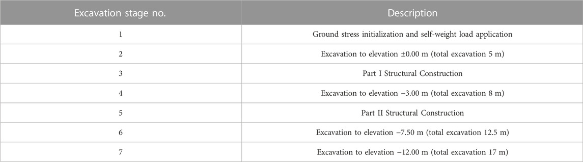
TABLE 2. Construction steps.
It should be noted that construction work on the underground structure, the superstructure of the surrounding station house pit, and the bus pit are all being done concurrently with the excavation of the foundation pit and construction of the support structure. The model activated the station house’s underground solid model in step 3 of the construction of the foundation pit of the production and living complex and activated the surface load acting on this part of the solid model in step 4 to simulate the effects of the station house’s superstructure to fully account for the effects of these factors. The bus station’s subsurface solid model was turned on in steps three and four of the production and living complex’s pit construction.
4 Data analysis
4.1 Analysis of horizontal deformation of foundation pit support structure of production and living complex building
Figure 5 depicts the piles’ horizontal displacement clouds in the production and living complex’s foundation pit under the condition of foundation pit bottom excavation. The clouds of the piles on the side near the transfer channel are depicted in Figures 5A (west side). The pile’s displacement in this instance exhibits a “parabolic” pattern of displacement along the vertical axis. There is a distinct demarcation on the horizontal scale between the displacement values on the side closest to the bus foundation pit (north side) and the side of the secondary release slope (south side). The area with the greatest displacement is shown by the blue box in the figure, and it is all located close to the side of the bus pit. The demarcation of the horizontal displacement is shown in the area denoted by the black box, which is situated at the intersection of the corner’s two inner supports. The action of the bus foundation pit, which is transmitted by the force of the inner support of the corner, may have caused a significant displacement to that side, which is the likely cause of this phenomenon. The blue-boxed areas of the northern grouting pile (Figures 5B) and the southern grouting pile (Figures 5D) both produced a significant displacement toward the northern side for the same reason. The results of the model are similar to the calculation and monitoring results of Guo et al. (2019). Different from the research results of Guo et al. (2019), due to the particularity of the joint excavation of the foundation pit group, the symmetrical area of the foundation pit of the production and living complex building shows a significant “push back displacement".
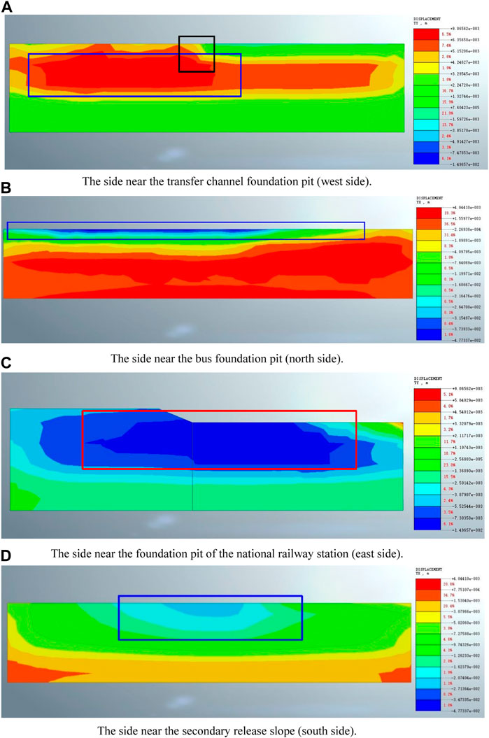
FIGURE 5. Horizontal deformation cloud map of the foundation support structure of production and living complex building. (A) The side near the transfer channel foundation pit (west side). (B) The side near the bus foundation pit (north side). (C) The side near the foundation pit of the national railway station (east side). (D) The side near the secondary release slope (south side).
4.2 Analysis of the horizontal deformation of the support structure of the adjacent foundation pit
Figure 6 depicts the ground connection wall of the transfer channel foundation pit’s lateral deformation. According to morphology, the deformation of the ground connection wall of the foundation pit can be roughly divided into three areas, the region shown by the red box in Figure 6, where the ground connection wall deforms in a “parabolic” shape toward the foundation pit while disregarding the influence of surrounding foundation pits and structures. In this project, the part marked by the red box is buried underground. Due to the division of the project site, no site pictures have been obtained. The active soil pressure zone of the ground connection wall close to the side of the adjacent pit was excavated and leveled in the area denoted by the blue box and the area denoted by the black box, leaving the portion of the interchange pit elevation above −3 m exposed on the ground (Figure 7). Due to this reason, the areas indicated by the blue box and the black box have both experienced overall horizontal displacement towards the direction adjacent to the foundation pit. The area indicated by the black box is adjacent to the integrated tourism bus foundation pit, and its excavation depth is greater than the production and living complex foundation pit adjacent to the area indicated by the blue box. Therefore, the horizontal displacement value indicated by the black box is greater than that indicated by the blue box.
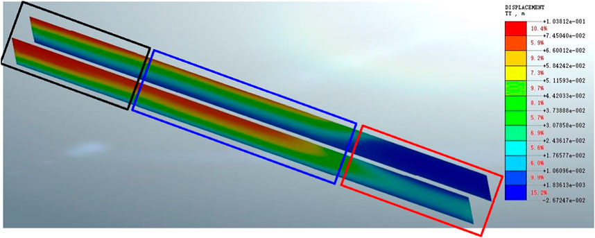
FIGURE 6. Horizontal deformation cloud map of the support structure of the transfer channel foundation pit.
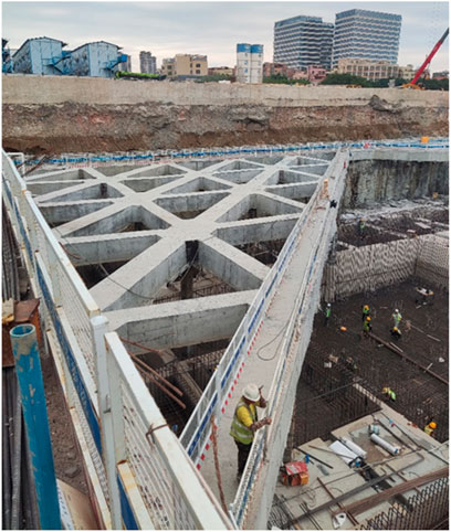
FIGURE 7. Site photo of the ground connection wall of the transfer channel foundation pit after general excavation.
Figure 8 extracts the typical curve of the transfer channel foundation pit’s ground connection wall deformation. In line with what is depicted in Figure 8, the wall that is connected to the ground exhibits two common deformation patterns. The displacement pattern of the red box area, which displays a “parabolic” displacement pattern toward the pit, is represented by the red curve. The maximum value of the displacement of the ground connection wall is less than 25 mm, but it is slightly larger on the side closest to the production and living complex. The larger displacement on this site may be due to the complex environment surrounding the production and living complex side and the complex stress field. The ground connection wall in the area of the blue and black lines exhibits a “cantilever” displacement pattern toward the side of the foundation pit of production and living complex building. The blue and black curves in Figure 8 demonstrate typical displacements in this region. By using the number, we can determine that the ground connection wall’s horizontal displacement in this area has increased beyond the typical engineering warning threshold, potentially posing a serious safety risk to the project. If such construction continues, the support structure may become unstable and the surrounding soil may crack and collapse. The construction site quickly backfilled the backpressure soil in the middle of the two foundation pits in the general excavation area after receiving the early warning from the model calculation results of this paper and monitoring and warning at the site, and accelerated the bottom slab-pouring operation of the transfer channel foundation pit (Figure 7). This action successfully controlled the deformation of this foundation pit and prevented the occurrence of safety accidents. This reflects the significance of this research for the safe and stabilized operation of this project.
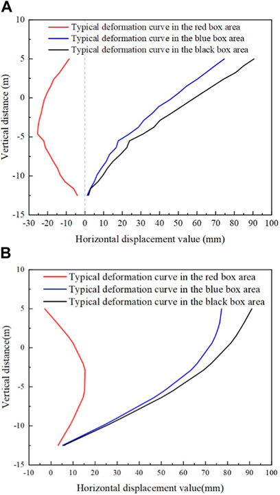
FIGURE 8. Typical curve of horizontal displacement of foundation connection wall of transfer channel foundation pit. (A) The ground connecting wall on the side of the building near the production and living complex. (B) Away from the production and living complex building side of the ground connecting wall.
4.3 Bending moment analysis of the foundation pit enclosure structure of the production and living complex building
Figure 9 extracts the typical curve of the transfer channel foundation pit’s ground connection wall bending moment of the production and living complex building at each construction step. The variation of bending moment shows that as the excavation depth of the foundation pit increases, the amplitude of bending moment significantly increases. The bending moment shapes in Figures 9A, B are similar. The surrounding structure generates negative bending moments towards the outside of the pit below the bottom. Above the bottom of the pit, the main positive bending moment is towards the pit, and a small amount of negative bending moment may occur near the top of the support pile. Figures 9C The negative bending moment generated near the top of the support pile is relatively large. Two layers of internal support were used for support at this location, which may be the reason for this internal force situation. The position shown in Figures 9D shows that due to the “pusback displacement” caused by the support, the deformation of the support pile at this position is relatively small, and the bending moment value is significantly smaller than the other three profiles.
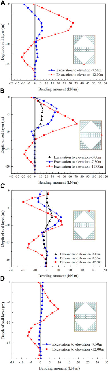
FIGURE 9. Typical bending moment of foundation pit connecting wall. (A) Bending moment situation on the side near the transfer channel foundation pit (west side). (B) Bending moment situation on the side near the secondary release slope (south side). (C) Bending moment situation on the side (east side) near the foundation pit of the National Railway Station. (D) Bending moment situation on the side near the bus foundation pit (north side).
4.4 Analysis of the vertical deformation of the foundation pit and surrounding soil of the production and living complex
Figure 10 depicts the vertical displacement of the production and living complex building foundation pit and the surrounding environment. The vertical direction shows a bulge deformation at the bottom of the foundation pit of the production and living complex. Among them, the position of the infill pile near the pit’s perimeter has the least vertical deformation, while the middle of the pit has the most. The overall uplift deformation pattern exhibits elastic uplift deformation. The overall uplift trend is shown in the platform area where the slope is released, which may be caused by the unloading of soil excavation. There is a settlement trend in the soil between the pit of the production and living complex and the foundation pit of the bus. The supporting structures of both foundation pits are generally displaced toward the foundation pit, resulting in a settlement pattern of low in the middle and high on both sides.

FIGURE 10. Vertical deformation cloud map of foundation pit and surrounding environment. (A) Typical curve of surface settlement outside the secondary release slope. (B) Typical vertical deformation of the soil between the pit of the production and living complex and the pit of the transfer channel.
Figure 11 shows the typical surface settlement data outside the pit after excavation. There are some differences between the surface settlement pattern outside the secondary release slope (Figures 11A ) and the “concave settlement profile” settlement model proposed by Pio-Go and Chang-Yu, (1998). According to the construction process simulation, the finite element model excavated a total of 17 m and obtained the maximum settlement value at 7.2 m, which is 0.42 times the excavation depth. The surface settlement value was 0.64 times the maximum settlement value at the start of the settlement profile, whereas the “concave settlement profile” settlement model was only 0.5 times the maximum settlement value at the start of the settlement profile. Meanwhile, in the secondary settlement area, the surface settlement value eventually converges to a settlement value of approximately 27 m but does not converge to 0. This difference could be attributed to the stratum and soil’s unique properties on the one hand, and the support mode of slope release followed by enclosure on the other, which differs from the simple internal support system.
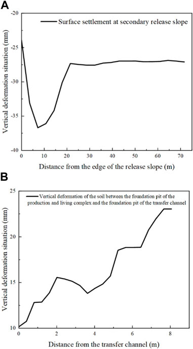
FIGURE 11. Typical vertical deformation curve of soil between pits. (A) Typical curve of surface settlement outside the secondary release slope. (B) Typical vertical deformation of the soil between the pit of the production and living complex and the pit of the transfer channel.
The soil between the foundation pit of the production and living complex and the foundation pit of the transfer channel, on the other hand, showed an uplift deformation pattern, with a larger uplift on the side close to the foundation pit of the production and living complex. The general excavated and leveled soil being unloaded causes the soil body in this area to rise as a whole. This uplift trend was exacerbated by the overall deformation of the support system of the transfer channel foundation pit toward the foundation pit of the production and living complex. Under the effect of the internal support of the corner, the support system of the production and living complex played a significant role, and its lateral deformation was significantly smaller than that of the pit of the interchange access building. However, this exacerbated the ground uplift near the production and living complex’s foundation pit.
The above soil deformation analysis reveals that the vertical deformation of surface soil in deep foundation pits with complex surrounding environments, particularly the foundation pit group, differs from the commonly used “concave settlement profile” and “spandrel-type settlement profiles. The deformation pattern of the adjacent foundation support structure is frequently related to the deformation pattern of the soil. Vertical deformation of the soil body between adjacent pits should be closely monitored to avoid excessive deformation.
4.5 Field monitoring set-up
Four inclined tubes were buried to measure the horizontal deformation of the foundation pit enclosure system in order to study the real deformation characteristics of the support structure in the context of the project site. Figure 12 depicts the actual monitoring points. The tilting pipe’s burial on the property is captured in Figure 13.
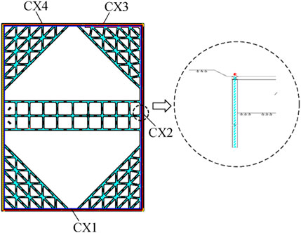
FIGURE 12. Foundation pit monitoring plan layout.
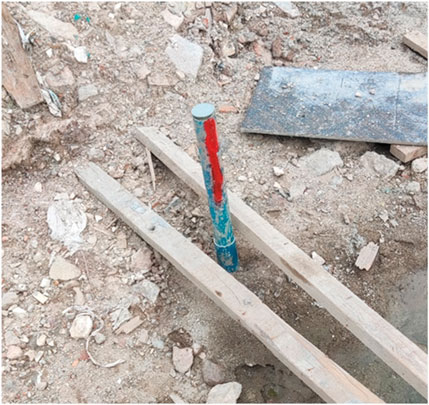
FIGURE 13. Burial of inclined tubes at the construction site.
The final formed pile top elevation has a significant difference between them due to the crown beam elevation gradient, so the inclined tubes CX3 and CX4 were placed on that side to observe the corresponding deformation. The need for soil treatment between the two adjacent pits made it impossible to deploy monitoring equipment on the side closest to the bus foundation pit.
4.6 Comparison analysis of finite element calculation results and field measurement data
The foundation pit support structure’s horizontal deformation warrants close attention and monitoring in real-world engineering. Comparing the monitoring data with the numerical simulation calculation results is a common means to verify the validity of the numerical simulation results. The data for the inclined tube after the foundation pit was built and the outcomes of the corresponding finite element analysis are extracted in Figure 14.
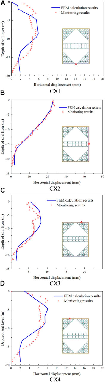
FIGURE 14. Comparison of foundation pit monitoring data and finite element calculation results. (A) CX1. (B) CX2. (C) CX3. (D) CX4.
The three monitoring points CX1, CX3, and CX4 all exhibit a “parabolic” horizontal displacement pattern when the two deformations are compared. The maximum calculated displacement value appears at a depth of −8.55 m, and the maximum horizontal displacement value is 5.86 mm, while the maximum monitoring value of CX1 displacement appears at −8 m, and the maximum horizontal displacement value is 5.32 mm. The maximum calculated displacement value appeared at a depth of −4.75 m, while the maximum monitoring value of CX4 displacement appeared at a depth of −2.5 m, with a maximum horizontal displacement value of 7.94 mm. The occurrence height at CX1 and the maximum monitored horizontal displacement value are very close to the predicted results. The maximum displacement emergence locations are higher than the predicted results, even though the horizontal displacement amplitudes at CX3 and CX4 are close to each other. In CX1 and CX4, the “belly bulge” area of the monitoring data is larger than that of the calculation results, and CX1, CX3, and CX4 all have a primary amplitude in the area closer to the pile top, which also makes their displacement shapes show an “R" shape. These shapes are not reflected in the calculation results. There are two main reasons for this error. On the one hand, the more typical stratum in the foundation pit area is used in the finite element calculation model, and the area in the model is regarded as the mean soil layer. However, there are still some differences between the actual stratum and the assumption of the model. This may bring some error to the calculation results. On the other hand, the additional load brought by the earthwork transportation path and construction machinery cannot be effectively reflected in the calculation, which also affects the accuracy of the calculation to a certain extent. The maximum monitoring value for CX2 is at depth −2 m and has a maximum horizontal displacement value of 23.76 mm; the maximum calculated value for CX2 is at depth 0 m and has a maximum horizontal displacement value of 22.91 mm. The large degree of fit between the monitoring data and the calculated results proves the reliability of the finite element simulation method and model simplification to a certain extent.
The existence of the nearby bus foundation pit may be the cause of the “cantilevered” displacement pattern at this location. The formed soil wedge was not complete because the support structure of the bus foundation pit prevented the slip crack surface from developing in the active soil wedge. Due to the low active earth pressure acting on the production and living complex pit’s support structure, the overall foundation pit support was offset in the direction of the bus foundation pit. The two-stage slope release support adds more load to the side opposite monitoring point CX2, intensifying the braced structure’s deflection on that side. Since CX2 has a larger displacement amplitude than the other three monitoring points, it also deviates significantly from the typical internally braced support structure in terms of support displacement pattern.
5 Conclusion
In this article, numerical modeling is utilized to examine the deformation of the foundation pit and the surrounding adjacent foundation pits during the excavation and support of the foundation pit of Guangzhou Baiyun Station’s production and living complex, and verify the numerical simulation results based on field monitoring data. The following primary findings are made from the analysis results.
(1) When designing deep foundation pits with a high number of excavations near a foundation group or a deep foundation pit, the usage of internal support forms must be carefully evaluated. The unloading induced by the adjacent pit or excavation may force the entire support structure to shift in the unloading direction. The magnitude of this overall movement was not quantitatively assessed in this study.
(2) The deformation of the foundation support structure is frequently related to the form of the support. Under the action of the internal support system, the foundation pit of the production and living complex building was displaced by 23 mm from the top of the support structure of the adjacent foundation pit, which indicated that the foundation pit support system may produce a displacement pattern similar to “cantilever” in the asymmetric case. Under the action of the internal suppor, the top of the retaining structure adjacent to the pit will have a smaller displacement, or even a “push-back displacement” towards the edge of the pit.
(3) The shape of vertical deformation of the surface soil outside the pits differs substantially from the previously listed rules due to the reciprocal influence of the support systems of the nearby foundation pits. Because of the total deformation of the supporting structure, the soil body between foundation pits may swell. Because of the deformation of other pits, the maximum surface settlement of the foundation pit at a depth of 0.42 times the excavation depth outside the pit, and the surface settlement value was 0.64 times the maximum settlement value at the start of the settlement profile.
Data availability statement
The original contributions presented in the study are included in the article/supplementary material, further inquiries can be directed to the corresponding author.
Author contributions
BL: Data curation, Funding acquisition, Methodology, Project administration, Writing–original draft. ZL: Data curation, Software, Writing–original draft. YC: Software, Validation, Writing–original draft. CX: Funding acquisition, Methodology, Project administration, Writing–review and editing. PL: Investigation, Software, Writing–review and editing. HD: Software, Supervision, Writing–review and editing.
Funding
The authors declare financial support was received for the research, authorship, and/or publication of this article. This work was supported by National Natural Science Foundation of China (NSFC Grant No. 52238009) and the National Science Fund of Jiangxi Province (No. 20223BBG71018).
Conflict of interest
Authors BL, YC, and PL were employed by China Railway Construction Group Co., Ltd.
The remaining authors declare that the research was conducted in the absence of any commercial or financial relationships that could be construed as a potential conflict of interest.
Publisher’s note
All claims expressed in this article are solely those of the authors and do not necessarily represent those of their affiliated organizations, or those of the publisher, the editors and the reviewers. Any product that may be evaluated in this article, or claim that may be made by its manufacturer, is not guaranteed or endorsed by the publisher.
References
Chen, H., Li, J., Yang, C., and Feng, C. (2022). A theoretical study on ground surface settlement induced by a braced deep excavation. Eur. J. Environ. Civ. Eng. 26 (5), 1897–1916. doi:10.1080/19648189.2020.1739563
Chen, Y., Tang, L., Ye, Y., Cheng, Z., and Zhou, Z. (2023). Effects of different chloride salts on granite residual soil: properties and water–soil chemical interaction mechanisms. J. Soils Sediments. 23 (4), 1844–1856. doi:10.1007/s11368-023-03445-7
Dan, K., and Sahu, R. (2012). A theoretical study on ground movement prediction for braced excavation in soft clay. Int. J. Geotech. Eng. 6 (1), 53–64. doi:10.3328/IJGE.2012.06.01.53-64
Dong, Y. P., Burd, H. J., and Houlsby, G. T. (2016). Finite-element analysis of a deep excavation case history. Géotechnique. 66 (1), 1–15. doi:10.1680/jgeot.14.P.234
Fan, X., Phoon, K., Xu, C., and Tang, C. (2021). Closed-form solution for excavation-induced ground settlement profile in clay. Comput. Geotech. 137, 104266. doi:10.1016/j.compgeo.2021.104266
Gao, Y., Yu, Z., Chen, W., Yin, Q., Wu, J., and Wang, W. (2023). Recognition of rock materials after hightemperature deterioration based on sem images via deep learning. J. Mater. Res. Technol. 25, 273–284. doi:10.1016/j.jmrt.2023.05.271
Guo, P., Gong, X., and Wang, Y. (2019). Displacement and force analyses of braced structure of deep excavation considering unsymmetrical surcharge effect. Comput. Geotech. 113, 103102. doi:10.1016/j.compgeo.2019.103102
Juang, C. H., Schuster, M., Ou, C., and Phoon, K. K. (2011). Fully probabilistic framework for evaluating excavation-induced damage potential of adjacent buildings. J. Geotech. Geoenviron. Eng. 137 (2), 130–139. doi:10.1061/(ASCE)GT.1943-5606.0000413
Li, H., Li, X., Fu, J., Zhu, N., Chen, D., Wang, Y., et al. (2023). Experimental study on compressive behavior and failure characteristics of imitation steel fiber concrete under uniaxial load. Constr. Build. Mater. 399, 132599. doi:10.1016/j.conbuildmat.2023.132599
Li, Z. (2021). Displacement monitoring during the excavation and support of deep foundation pit in complex environment. Adv. Civ. Eng. 2021, 1–7. doi:10.1155/2021/5715306
Liu, B., Zhang, D., and Xi, P. (2019). Influence of vehicle load mode on the response of an asymmetrically-loaded deep excavation. Ksce J. Civ. Eng. 23 (8), 3315–3329. doi:10.1007/s12205-019-0511-6
Liu, B., Zhang, D., Yang, C., and Zhang, Q. (2020). Long-term performance of metro tunnels induced by adjacent large deep excavation and protective measures in nanjing silty clay. Tunn. Undergr. Space Technol. 95, 103147. doi:10.1016/j.tust.2019.103147
Liu, G. B., Jiang, R. J., Ng, C. W. W., and Hong, Y. (2011). Deformation characteristics of a 38 m deep excavation in soft clay. Can. Geotech. J. 48 (12), 1817–1828. doi:10.1139/t11-075
Liu, H., Li, X., Yu, Z., Tan, Y., Ding, Y., Chen, D., et al. (2023a). Influence of hole diameter on mechanical properties and stability of granite rock surrounding tunnels. Phys. Fluids 35 (6). doi:10.1063/5.0154872
Liu, S., and Li, X. (2023). Experimental study on the effect of cold soaking with liquid nitrogen on the coal chemical and microstructural characteristics. Environ. Sci. Pollut. Res. Int. 30 (13), 36080–36097. doi:10.1007/s11356-022-24821-9
Liu, S., Sun, H., Zhang, D., Yang, K., Li, X., Wang, D., et al. (2023b). Experimental study of effect of liquid nitrogen cold soaking on coal pore structure and fractal characteristics. Energy 275, 127470. doi:10.1016/j.energy.2023.127470
Mangushev, R. A., Osokin, A. I., and Garnyk, L. V. (2016). Experience in preserving adjacent buildings during excavation of large foundation pits under conditions of dense development. Soil Mech. Found. Eng. 53 (5), 291–297. doi:10.1007/s11204-016-9401-9
Ng, C. W. W., Hong, Y., Liu, G. B., and Liu, T. (2012). Ground deformations and soil–structure interaction of a multi-propped excavation in shanghai soft clays. Géotechnique. 62 (10), 907–921. doi:10.1680/geot.10.P.072
Ou, C., and Hsieh, P. (2011). A simplified method for predicting ground settlement profiles induced by excavation in soft clay. Comput. Geotech. 38 (8), 987–997. doi:10.1016/j.compgeo.2011.06.008
Pio-Go, H., and Chang-Yu, O. (1998). Shape of ground surface settlement profiles caused by excavation. Can. Geotech. J. 35 (6), 1004–1017. doi:10.1139/t98-056
Schuster, M., Kung, G. T., Juang, C. H., and Hashash, Y. M. A. (2009). Simplified model for evaluating damage potential of buildings adjacent to a braced excavation. J. Geotech. Geoenviron. Eng. 135 (12), 1823–1835. doi:10.1061/(ASCE)GT.1943-5606.0000161
Shen, Y., Zhang, D., Wang, R., Li, J., and Huang, Z. (2023). Sbd-k-medoids-based long-term settlement analysis of shield tunnel. Transp. Geotech. 42, 101053. doi:10.1016/j.trgeo.2023.101053
Shouhua, L., Junsheng, Y., Jinyang, F., and Xiangcou, Z. (2019). Performance of a deep excavation irregular supporting structure subjected to asymmetric loading. Int. J. Geomech. 19 (7). doi:10.1061/(asce)gm.1943-5622.0001468
Son, M., and Cording, E. J. (2011). Responses of buildings with different structural types to excavation-induced ground settlements. J. Geotech. Geoenviron. Eng. 137 (4), 323–333. doi:10.1061/(ASCE)GT.1943-5606.0000448
Song, D., Chen, Z., Dong, L., Tang, G., Zhang, K., and Wang, H. (2020). Monitoring analysis of influence of extra-large complex deep foundation pit on adjacent environment: a case study of zhengzhou city, China. Geomatics, Nat. Hazards Risk 11 (1), 2036–2057. doi:10.1080/19475705.2020.1823492
Tan, Y., and Li, M. (2011). Measured performance of a 26 m deep top-down excavation in downtown shanghai. Can. Geotech. J. 48 (5), 704–719. doi:10.1139/t10-100
Tan, Y., and Wei, B. (2012). Observed behaviors of a long and deep excavation constructed by cut-and-cover technique in shanghai soft clay. J. Geotech. Geoenviron. Eng. 138 (1), 69–88. doi:10.1061/(ASCE)GT.1943-5606.0000553
Wang, L., Luo, Z., Xiao, J., and Juang, C. H. (2014). Probabilistic inverse analysis of excavation-induced wall and ground responses for assessing damage potential of adjacent buildings. Geotech. Geol. Eng. 32 (2), 273–285. doi:10.1007/s10706-013-9709-4
Xu, C., Lin, Z., Jiang, Y., Shi, Y., Fan, X., Xiong, Z., et al. (2022). Research on the spatial effect of foundation pit under asymmetric loads. Front. Mater. 9. doi:10.3389/fmats.2022.976696
Xu, C. J., Xu, Y. L., Lin, H. H., and Sun, F. M. (2013a). Influences of vehicle loads on braced excavation in soft clay. Appl. Mech. Mater. 353-356, 146–151. doi:10.4028/www.scientific.net/AMM.353-356.146
Xu, C. J., Yin, M., and Lin, G. (2013b). Characters analysis of the retaining structure of the foundation pit under local load. Appl. Mech. Mater. 477-478, 448–452. doi:10.4028/www.scientific.net/amm.477-478.448
Yan, J., Kong, L., and Wang, J. (2023a). Evolution law of small strain shear modulus of expansive soil: from a damage perspective. Eng. Geol. 315, 107017. doi:10.1016/j.enggeo.2023.107017
Yan, J., Kong, L., Xiong, C., and Xu, G. (2023b). Damage analysis of shear mechanical behavior of pile–structural soil interface considering shear rate effect. Acta Geotech. 18, 5369–5383. doi:10.1007/s11440-023-01912-6
Ye, S., Zhao, Z., and Wang, D. (2021). Deformation analysis and safety assessment of existing metro tunnels affected by excavation of a foundation pit. Undergr. Space. 6 (4), 421–431. doi:10.1016/j.undsp.2020.06.002
Zeng, F., Zhang, Z., Wang, J., and Li, M. (2018). Observed performance of two adjacent and concurrently excavated deep foundation pits in soft clay. J. Perform. Constr. Facil. 32 (4), 4018040. doi:10.1061/(ASCE)CF.1943-5509.0001184
Zhang, G., and Wu, D. X. (2014). Analysis of foundation pit accidents due to expansive soil in hefei district. Appl. Mech. Mater. 501-504, 331–335. doi:10.4028/www.scientific.net/AMM.501-504.331
Zhang, J., Li, X., Qin, Q., Wang, Y., and Gao, X. (2023). Study on overlying strata movement patterns and mechanisms in super-large mining height stopes. Bull. Eng. Geol. Environ. 82 (4), 142. doi:10.1007/s10064-023-03185-5
Zhang, R., Zhang, W., and Goh, A. T. C. (2021). Numerical investigation of pile responses caused by adjacent braced excavation in soft clays. Int. J. Geotech. Eng. 15 (7), 783–797. doi:10.1080/19386362.2018.1515810
Keywords: karst, stratum instability zone, foundation pit group, deformation, numerical simulation
Citation: Li B, Lin Z, Chen Y, Xu C, Li P and Ding H (2023) Numerical analysis for supporting and deformation of complex foundation pit groups in unstable areas of karst strata. Front. Earth Sci. 11:1283184. doi: 10.3389/feart.2023.1283184
Received: 25 August 2023; Accepted: 20 October 2023;
Published: 01 November 2023.
Edited by:
Xuelong Li, Shandong University of Science and Technology, ChinaReviewed by:
Cai Peichen, Chang’an University, ChinaJunbiao Yan, Chinese Academy of Sciences (CAS), China
Copyright © 2023 Li, Lin, Chen, Xu, Li and Ding. This is an open-access article distributed under the terms of the Creative Commons Attribution License (CC BY). The use, distribution or reproduction in other forums is permitted, provided the original author(s) and the copyright owner(s) are credited and that the original publication in this journal is cited, in accordance with accepted academic practice. No use, distribution or reproduction is permitted which does not comply with these terms.
*Correspondence: Zhaorui Lin, MTAwNjE2MTA3MkBxcS5jb20=