 Jiawei Kang
 Guohua Deng1,2*
- 1Institute of Geotechnical Engineering, Xi’an University of Technology, Xi’an, China
- 2Xi’an Loess Underground Project Technology Consulting Co., Ltd., Xi’an, China
- 3China Jikan Research Institute of Engineering Investigations and Design, Co., Ltd., Xi’an, China
The sandy cobble stratum presents a high risk for underground tunnel construction due to its low cohesive properties and susceptibility to loosening and falling. The use of Advanced ductule for grouting reinforcement inevitably results in vibrations, and understanding how these vibrations propagate is crucial in selecting tunnel engineering support schemes and responding to accident risks. Based on a bored tunnel under construction in Xi’an, field vibration propagation characteristics testing were carried out for advanced ductile installation. The time-history response and frequency distribution characteristics of the vibration velocity within the tunnel face under sandy cobble stratum conditions were studied, and the law of vibration propagation attenuation within the tunnel face range was obtained. The results showed that: 1) During the conduit drilling process, the tunnel face mainly experienced vertical vibrations, with the horizontal velocity amplitude accounting for only 15%–20% of the vertical velocity amplitude. At a distance of 1.0 m from the conduit, the vertical velocity amplitude reaches 10.602 mm/s, and the vibration energy concentrates mainly in the frequency range of 150–250 Hz. At a distance of 1.5 m from the conduit, the bidirectional vibration velocity significantly attenuates; 2) The vibration characteristics within the tunnel face can be classified into three primary areas: “Loose and Falling” area, “Significant Vibration” area, and “Vibration Attenuation” area. Loose, falling and significant vibrations occurred mainly within a range of about 1.25 m around the conduit. 3) As the diameter of the conduit decreases, the amplitude of vertical vibration velocity decreases by about 20%. By reducing the design diameter of the advanced ductule in a reasonable manner, it is possible to effectively mitigate the impact of vibration caused by the sandy cobble stratum during installation. This can yield a positive impact, curtailing the occurrence of the tunnel’s collapse phenomenon and ensuring its stability.
1 Introduction
The sandy cobble stratum is a high risk layer during the construction of underground tunnels, given its loose nature. In the past, collapse accidents occurred frequently during the excavation process of these tunnels, posing a significant danger to the safety of engineering construction. Advanced ductile reinforcement methods are commonly used due to their cost-effectiveness, uncomplicated construction process, and minimal space requirements. Upon completion of the earthwork excavation in a single cycle of tunnel construction, a grid arch is quickly erected. High-pressure air picks are used to form perforations according to the contour line of the Advanced Ductule layout determined by the design, followed by manual insertion of the ductule, ensuring that the exposed length meets the design specifications. The tail of the ductule is welded to the grid arch to ensure stability and structural integrity. However, during the installation of the advanced ductules, vibrations are inevitably generated, leading to the loosening and collapse of the cohesionless sand and gravel layer. This problem commonly occurs in a variety of engineering practices, with collapse depths and heights ranging from tens of centimeters to several meters. This problem can affect the stability of the face and arch of the tunnel, and in severe cases, lead to a counterproductive effect (Zhou et al., 2018; Liu et al., 2020; Di et al., 2022; Qin et al., 2022; Le et al., 2023). At later stages, this problem can only be solved through a large amount of initial support and grouting behind it, which not only affects the safety of tunnel construction, but also increases investment.
Currently, researchers are placing greater emphasis on major technical issues that arise in tunnel excavation in sandy cobble strata, such as surrounding rock pressure (Zhang et al., 2017; Lin et al., 2021; Zhang et al., 2022), support systems (Li et al., 2020; Cheng et al., 2023), grouting reinforcement (Mei et al., 2021), and deformation control (Zhang et al., 2017; Lin et al., 2021). However, when it comes to construction details, relatively little research has been done. This has resulted in a high proportion of engineering accidents due to inadequate implementation of ideal designs. Therefore, some scholars have proposed the prudent use of advanced ductule in these formations. For example (Wu, 2009), conducted systematic field tests on ductules with different diameters, studying maximum drilling depth, conduit failure, and local collapse under three conventional drilling methods for advanced ducts. A design scheme is recommended for advanced ductules with fine diameters, short lengths, and high frequencies, which is more feasible for construction. At present, the most commonly used installation methods for ductules are high pressure air guide holes, pneumatic picks, or a combination of both. High pressure wind drilling is less disruptive to formation and is suitable for pure sand layers; however, it may not solve the problem of large particle size pebbles in sand and gravel layers. The combination of air pick-up and drilling is currently the most popular method used in sand and gravel layers. However, the jacking of the air pick inevitably causes some disturbance to the sandy cobble layers.
Due to the special mechanical properties of the sandy cobble layer, scholars (Guo et al., 2018; Wu et al., 2022; Fang et al., 2023) have conducted several field vibration propagation attenuation tests on environmental vibration problems induced during shield tunnel excavation in the past. However, there has been no systematic study of vibration effects during bored tunnel construction. However, the vibration effect during the formation of ductules in sand and gravel underground tunnels exists objectively, leading to frequent local tunnel collapse accidents. This paper intends to select a tunnel under construction in Xi’an to conduct in-situ vibration monitoring tests, analyze the propagation law of vibration during the drilling process of advanced ductules, and provide a basis for addressing the collapse risk of sand and gravel layers during tunnel implementation.
2 Experimental procedure
2.1 Geological overview of the test site
This vibration monitoring test is located in Baqiao District, Xi’an City, Shaanxi Province. This tunnel is carried out using the “bending tunneling method”, with an advanced length of 3–5 m on the upper step and a spacing of 0.5 m between the grid arches. The length of excavation per step is consistent with the grid arch space.
Figure 1 shows the geological profile of the test section. The soil layer in the tunnel body is mainly composed of alluvial-proluvial silty clay, sand, and middle pleistocene alluvial gravel. The observed long-term phreatic water level was found to be 25.5 m below the ground surface and below the tunnel base. At the top of the tunnel arch, there is a layer of sand and gravel, that is, about 2 m thick. The soil layer within the tunnel body mainly consists of round gravel, pebbles, and medium sand. Inside the tunnel base, the soil layer is mainly composed of silty clay.
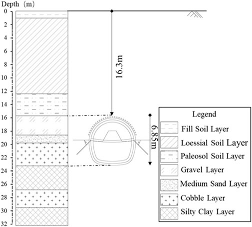
FIGURE 1. Geological profile of the test section.
Figure 2 shows the particle size distribution curve of the characteristic soil layer at the test section location. The pebble layers on the experimental site appear to have an uneven distribution, with the original rock being mainly composed of granite particles ranging in size from 3 to 7 cm, and the maximum size being 12 cm. About 28% of the particles are larger than 10 cm, including a mix of gravel sand and round gravel, along with some clay filling. The gradation of cobble layer is also uneven, with the original rock mostly consisting of granite particles ranging in size from 0.2 to 2 cm, and a maximum size of 3 cm. In this layer, moderate amounts of gravel, sand, and pebbles are present, along with some clay filling. As for the medium sand layer, it has an uneven quality, with granite being the predominant rock type. The main mineral components of this layer are feldspar and quartz, along with moderate amounts of gravel sand, round gravel, and some clay filling.

FIGURE 2. Particle size distribution curve of characteristic soil layers at the test section.
2.2 Advanced ductule and installation methods for testing
Taking into account factors such as tunnel operating space, advanced ductile processing and manufacturing capabilities, and slurry diffusion requirements, two sets of ductile diameters and three kinds of lengths of ductile material were prepared for the test. The advanced ductules is produced using φ 32/φ 42 mm steel ductules, which are segmented into lengths of 1.5, 2.0, and 3.0 m. One end is made into a conical shape 300 mm long and sealed using a hot melt machine, as shown in Figure 3A). A joint is provided at the end of the conduit, which is directly connected to the high pressure pneumatic pick. Use a high-pressure impact force to place the leading ductules inside the sand layer, as shown in Figure 3B).
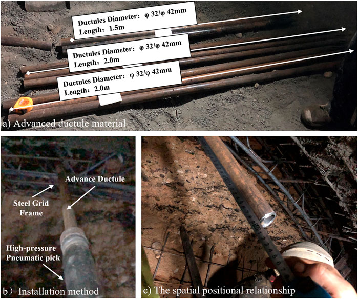
FIGURE 3. Schematic diagram of using small conduits and installation methods in the experiment.
2.3 Test conditions and monitoring points layout
Supplementary Table S1 presents the experimental conditions for this study, detailing the advanced ductile test. The test was performed under different specifications of ductules, powered by high pressure pneumatic picks. In the event of encountering large diameter pebble layers during installation, and if they cannot be easily driven through, the installation angle of the conduit will be adjusted accordingly. If the conduit cannot be adjusted, the vibration test will be terminated. Once the test is complete, the actual location of the advance conduit into the soil will be marked. The conduit will be pulled out from the inside of the formation, and the length of the conduit will be recorded. In addition, the condition of the conduit body and the characteristics of the sealing section will be observed.
To monitor vibration levels during the installation of advanced ductule, three sets of vibration monitoring points are installed around the installation site with a horizontal separation of 0.5 m between each point. These monitoring points are located along the tunnel face and empty surface as shown in Figure 4, with both horizontal and vertical vibration pick-ups installed at each point. The purpose of recording the horizontal and vertical components of vibration in real time at each monitoring point is to analyze the attenuation and propagation of vibration in the surrounding sand and gravel layer within a radius of 1.5 m of the conduit installation.
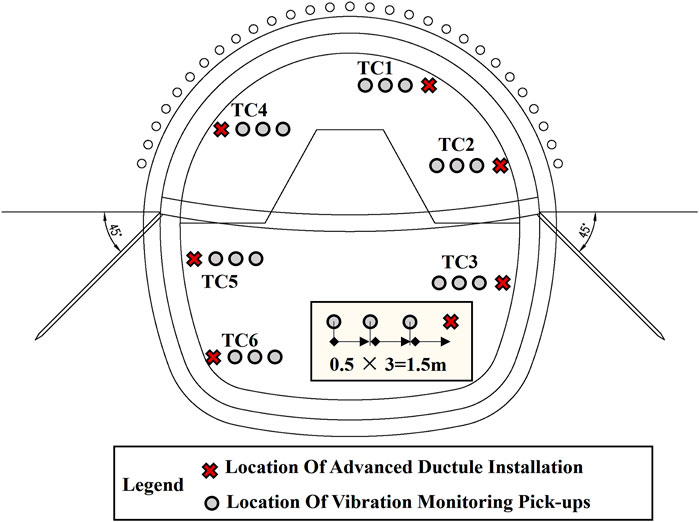
FIGURE 4. Layout of vibration test monitoring points and schematic diagram of implementation points for each working condition.
Figure 5A shows the layout of field vibration monitoring points. The vibration pickup uses 891-II and 941-B speed sensors, which offer ranges of 0.3 and 1.4 m/s, respectively. The frequency response range of the sensors is 0.17–100 Hz. The vibration data acquisition instrument used herein is a dynamic signal acquisition analyzer with a model INV3060A, as shown in Figure 5B. Before installing the vibration pick-up, a pit is hand-dug at the tunnel face, and a wooden board is placed horizontally as a support platform. The vibration pickup is placed above the wood panel to ensure accurate recording of the direction of the vibration component, as shown in Figure 5C. The data collection system is then connected. To verify the correct installation and accurate data transmission, we check the stability of each monitoring point and any changes in the data. If no significant fluctuations or anomalies are observed, we consider the vibration pickup properly connected and the data transmission line accurately established, as shown in Figure 5D.
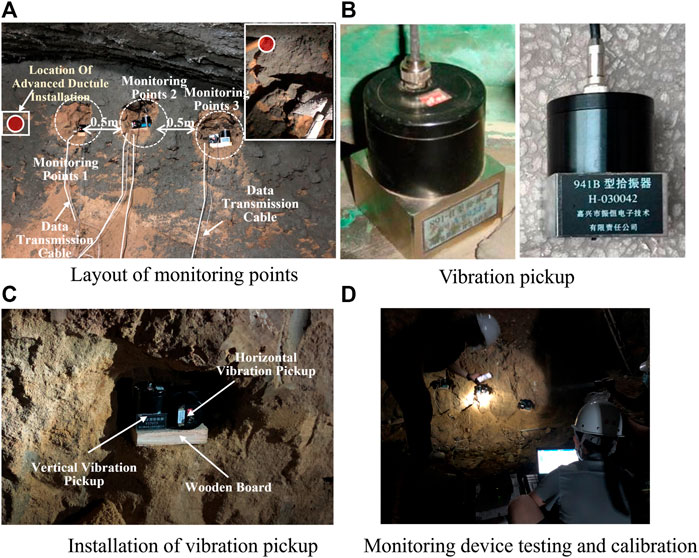
FIGURE 5. Schematic diagram of the arrangement, installation, and calibration of vibration pickup measuring points.
3 Analyses of field measurements
3.1 Actual installation depth and ductules body characteristics
Supplementary Table S1 summarizes the actual penetration depth of the conduit across each test condition. There are large diameter pebble layers distributed within the range of conduit installation, which cannot be fully penetrated. During the installation process, the angle is difficult to adjust and cannot avoid the pebble body. Finally, the conduit is continuously installed for about 3 min before terminating the test.
During the installation of the advanced ductules, sand and gravel were loose and fell above the actual installation position and within the free range of the side wall. It can be observed that the structure of the conduit body is basically intact, and the sealing section has undergone severe deformation and damage.
3.2 Characteristics of vibration propagation
Figure 6; Figure 7; Figure 8; Figure 9 shows vertical and horizontal velocity response curves and velocity spectrum characteristics at each vibration monitoring point during TC1 installation.
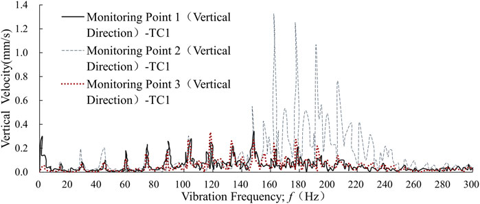
FIGURE 6. Vertical velocity frequency distribution characteristics at each vibration monitoring point during TC1 installation.
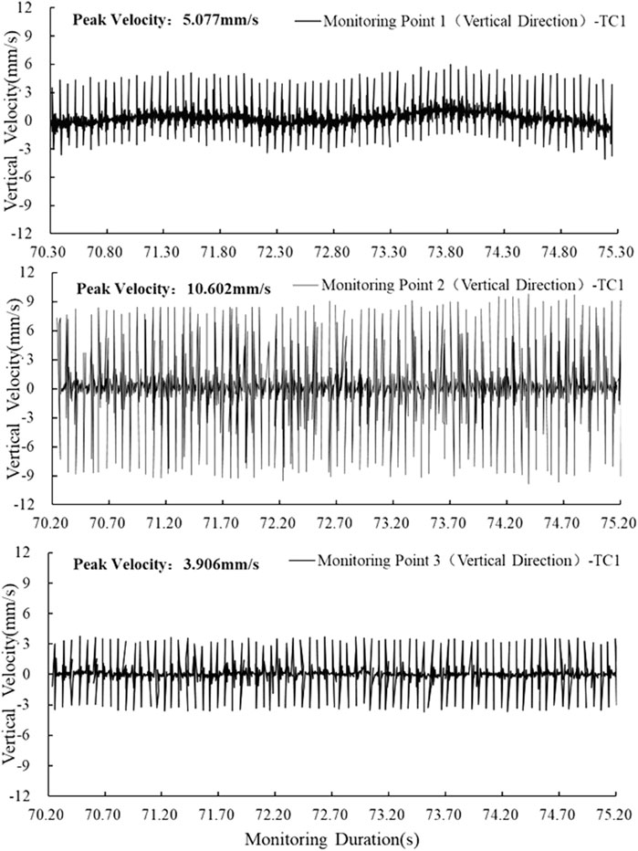
FIGURE 7. Vertical velocity time-history curve at each vibration monitoring point during TC1 installation.
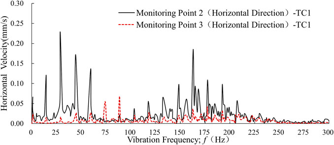
FIGURE 8. Horizontal velocity frequency distribution characteristics at each vibration monitoring point during TC1 installation.
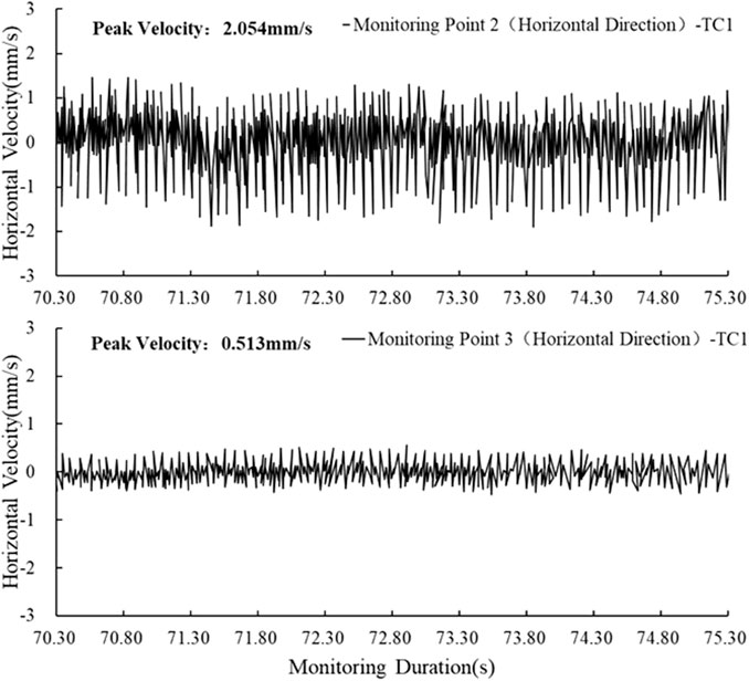
FIGURE 9. Horizontal velocity time-history response curves at each vibration monitoring point during TC1 installation.
During the implementation of the advanced ductule, the maximum vertical peak velocity was observed at a distance of 1.0 m from the conduit installation point, specifically at monitoring point 2, reaching a velocity of 10.602 mm/s. The vibration energy of the ductules was mainly concentrated in a frequency range of 150–250 Hz. At a distance of 1.5 m from the installation point (monitoring points 3), the vertical peak velocity is reduced to 3.906 mm/s, with most of the vibration energy distributed in the frequency range of 50–150 Hz. Similarly, at Monitoring Point 1, located 0.5 m from the installation point, the vertical peak velocity was found to be 5.077 mm/s, which fell between velocities recorded at Monitoring Points 2 and 3. The dominant vibration frequency at this point was similar to that observed at Monitoring Point 3, but with a reduction in vibration energy compared to Monitoring Point 2.
Combined with the field implementation process, the reason for this law of attenuation of vibration velocity is that within the range of vibration monitoring points 1–2, the vibration energy caused by the installation of advanced ductules dissipated in the form of loose and falling surrounding sand and gravel, thereby reducing the vibration velocity test value.
Compared to vertical vibration, horizontal vibration during installation ductules has a narrow range of numerical values. At a distance of 1.0 m from the installation point (monitoring points 2), the horizontal vibration velocity reaches its maximum, with a velocity amplitude of 2.054 mm/s. This amplitude is 20% of the vertical velocity amplitude at the same monitoring points. At monitoring points 3, located 1.5 m from the installation point, the horizontal velocity amplitude is 0.513 mm/s, which accounts for 15% of the vertical velocity amplitude. These findings suggest that horizontal vibration is less impactful than vertical vibration during the installation of advanced ductule.
The vibration energy of the ductules is mainly concentrated in the frequency bands 0–50 and 125–200 Hz at a distance of 1.0 m from its installation position (monitoring points 2). At a distance of 1.5 m from the ductile installation position (monitoring points 3), horizontal vibration energy is distributed over a wide frequency range of 50–250 Hz, and its velocity amplitude significantly decreases. This test result correlates with the law of vertical velocity attenuation.
3.3 The Influence of ductules diameter on the vibration characteristics
Figures 10, 11 shows the vertical and horizontal velocity spectrum characteristics and velocity time history curve of vibration monitoring points 2 under two different conduit diameter conditions (TC1 and TC4).
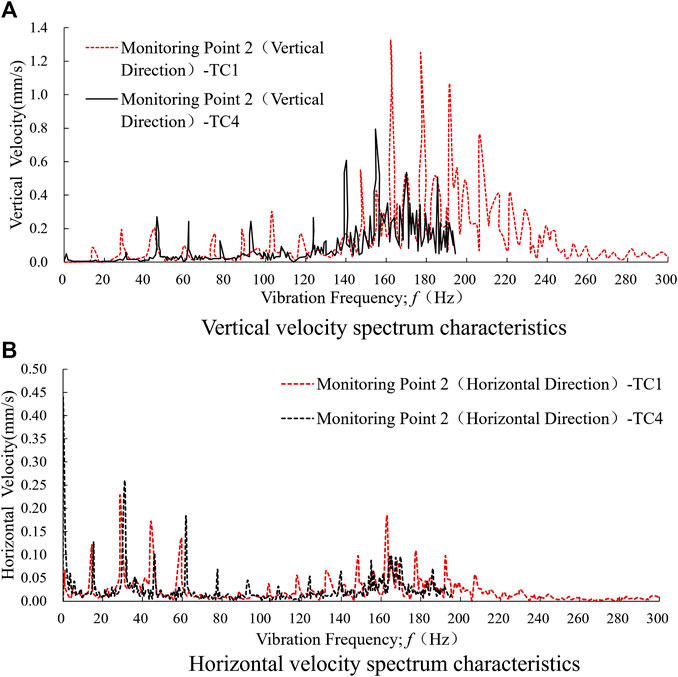
FIGURE 10. Velocity frequency distribution characteristics of vibration monitoring points 2 under two different conduit diameter conditions (TC1 and TC4).
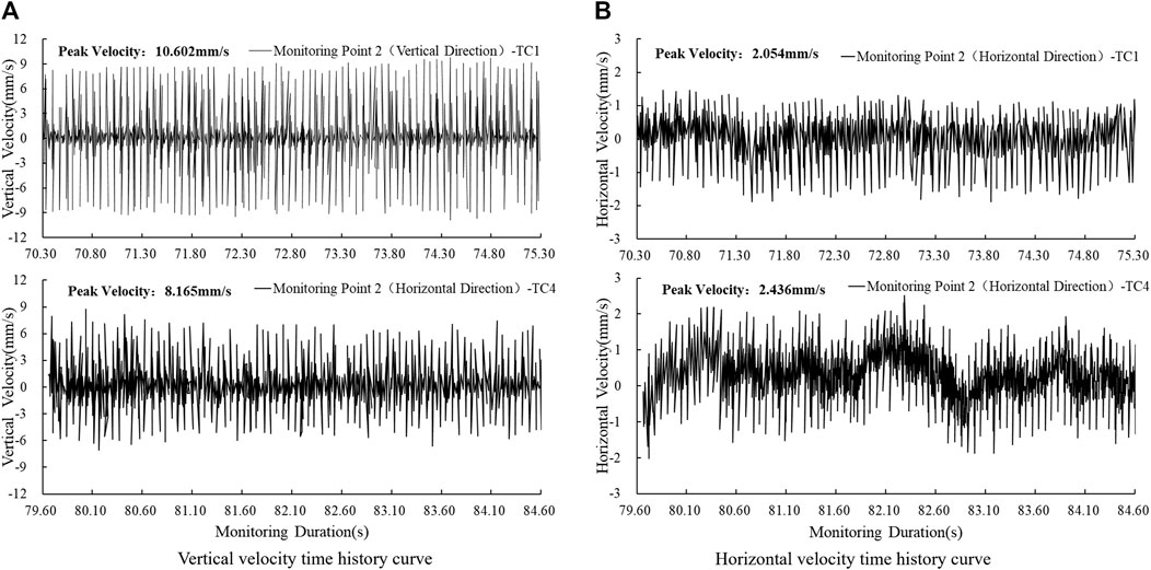
FIGURE 11. Velocity time-history curve of vibration monitoring points 2 under two different conduit diameter conditions (TC1 and TC4).
During the installation of ductules of different ductules diameters, the sand and gravel layers at the installation site exhibited similar spectral distribution characteristics. Vibration energy was observed to be mainly vertical, with the majority of its frequency concentrated between 150 and 250 Hz. Meanwhile, horizontal vibration energy was found to be mainly distributed in two frequency bands, at 0–50 and 125–200 Hz.
Reducing the diameter of the duct leads to a decrease in its vibration energy. In the frequency range of 150–250 Hz, when the conduit diameter is reduced from φ 42 to φ 32 mm, the corresponding vertical vibration velocity decreases from 1.31 to 0.80 mm/s. The maximum vertical velocity amplitude also decreases from 10.602 to 8.165 mm/s with a reduction ratio of 20%. Horizontal vibration spectrum characteristics remain similar under both conditions with maximum horizontal velocity amplitudes of 2.436 and 2.054 mm/s respectively. These values are within a relative range.
4 Discussion
4.1 Vibration law of ductules installation
During the installation of advanced ductules, the vibration effect caused by the interaction between the structure of the conduit body and the sand and gravel layer of the tunnel, as well as the diffusion and attenuation law within the face range of the tunnel, are prominent problems in identifying the range of loose and collapsed sand and gravel bodies, optimizing support measures for concealed excavation tunnels, and responding to engineering risks.
Figure 12 shows the propagation attenuation characteristics within the tunnel face range. The main statistical objects are velocity amplitudes at each monitoring point under two types of advanced ductile diameter conditions.
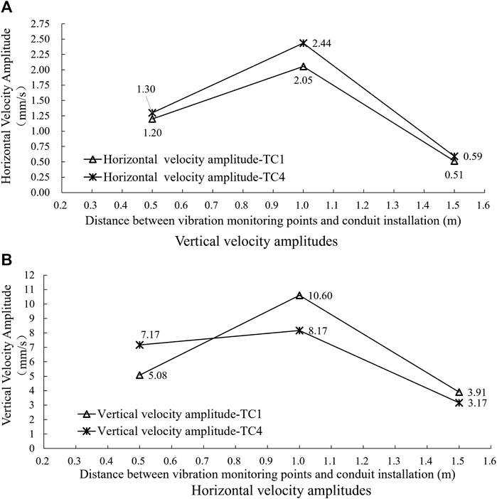
FIGURE 12. Characteristics of velocity amplitude attenuation within the range of the palm during the installation of advanced ductule.
During the installation of advanced ductule, the vertical and horizontal velocity amplitudes within the tunnel face exhibit similar patterns of diffusion attenuation. This is because sand and gravel in the range of 25–75 cm around the location of the advanced ductile installation undergo “loose and fall”, leading to the dissipation of vibration energy. From the test results, it was observed that the amplitude of the vibration velocity has a numerical range. The maximum amplitude of the vertical and horizontal vibration velocity was found to occur at a distance of 1.0 m from the installation position of the ductules (monitoring points 2).
The vibration velocity within the tunnel face decreases significantly as the distance from the installation position of the conduit increases. For example, when comparing Measurement Point 3 with Point 2, there is an attenuation of 50%–60% in its vibration speed. Further, it was observed that as the diameter of the conduit decreases (from φ 42 to φ 32 mm), the amplitude of the bidirectional velocity reduces by about 20% at a distance of 1.0 m (monitoring points 2) from the installation position of the ductules.
To summarize, during the advanced ductile installation process, the range of vibration disturbance within the tunnel face is mainly concentrated within 1.5 m of the installation location in the sandy cobble stratum. Based on the vibration response characteristics obtained from this field monitoring, the center position of adjacent measurement points is used as the regional boundary, the disturbance propagation attenuation characteristics of the sand and gravel layer are classified into three areas: “Loose and Falling” area, “Significant Vibration” area, and “Vibration Attenuation” area. Figure 13 shows the specific division diagram. These findings provide a better understanding of the dynamic characteristics of the advanced ductile installation process and can be used to improve future operation and maintenance practices.
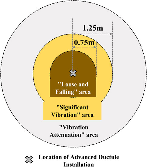
FIGURE 13. Schematic diagram of disturbance area division for advance ductule installation in sandy cobble stratum.
4.2 Suggestions for engineering measures
By conducting field monitoring vibration characteristics during advanced ductule installation in sandy cobble stratum, the vibration propagation characteristics and attenuation laws within the tunnel face range during the process of using high pressure pneumatic picks for jacking were presented. In order to effectively control the engineering risks of sandy cobble stratum, the following engineering measures and suggestions are proposed:
(1) It is recommended to carefully consider the advanced ductules grouting reinforcement scheme during the design process of the support scheme for the sandy cobble stratum underground excavation tunnel; It is recommended to prioritize the use of low vibration drilling methods such as high-pressure air drilling, and the use of high-pressure air picks for direct jacking is only recommended as an auxiliary measure.
(2) If it is necessary to use it, it is recommended to minimize the diameter and length of the conduit as much as possible to reduce the risk of loosening, falling, or even collapse of the sandy cobble layer caused by disturbance during installation; It is recommended to take cover protection measures for the sand and gravel layer within 1.25 m around the advance conduit;
(3) Before the excavation of bored tunnels, it is necessary to thoroughly investigate the particle size distribution characteristics of sandy cobble layer, and evaluate the feasibility of the advanced ductules installation plan; ensure welding quality, improve the strength of the conduit mouth, and ensure the success rate of the first installation of the advanced ductules.
5 Conclusion
In this article, a series of research work was carried out on the time-history response law and velocity spectrum distribution characteristics of vibration velocity in the face of the tunnel by conducting field vibration propagation characteristics testing tests for advanced ductules installation under sandy cobble stratum. The vibration energy diffusion and attenuation law during the advanced ductules installation process was obtained. It has certain reference significance for optimizing the design of excavation support schemes for underground tunnels under such geological conditions. The main conclusions are as follows:
(1) During the design and construction process of underground excavation tunnels in sandy cobble stratum, the drilling plan of advanced ductule should be reasonably matched with the characteristics of the strata. If not properly selected, significant vibration effects will occur, leading to the risk of loosening, falling blocks, and even collapse of the surrounding sandy cobble stratum.
(2) During the installation of advanced ductule, when encountering a large diameter pebble layer, the vibration velocity within the tunnel face area increases significantly, mainly in the vertical direction, with a horizontal velocity amplitude of about 15%–20% of the vertical direction. Before tunnel excavation, the stability of the sandy cobble stratum under vibration should be evaluated according to the specific geological conditions of the site.
(3) During the installation of advanced ductule, the vibration propagation characteristics within the tunnel face can be divided into three main areas: “Loose and Falling” area, “Significant Vibration” area, and “Vibration Attenuation” area. During the excavation and support process of bored tunnels, effective protective measures should be taken to control the loosening and falling of sand and gravel layers within the range of 0–0.75 m around the advance conduit. Sand and gravel layer in the range of 0.75–1.25 m around have a large amplitude of vibration velocity. During the excavation and support process of underground tunnels, it is necessary to minimize the disturbance to the strata within the area. If necessary, reinforcement measures can be taken to maintain the stability of the tunnel face;
(4) Based on the vibration monitoring results under different conduit diameter conditions, it is recommended to reasonably reduce the design diameter of the advanced ductules during the bored tunnel construction process, which has beneficial effects on suppressing the collapse of sandy cobble stratum and maintaining the stability of the tunnel face.
Data availability statement
The original contributions presented in the study are included in the article/Supplementary Material, further inquiries can be directed to the corresponding author.
Author contributions
JK: Writing–original draft, Formal Analysis, Visualization. GD: Conceptualization, Funding acquisition, Writing–review and editing. KZ: Investigation, Visualization, Writing–review and editing. SS: Supervision, Writing–review and editing.
Funding
The author(s) declare financial support was received for the research, authorship, and/or publication of this article. This work was financially supported by the National Natural Science Foundation of China (Grant No. 52178355) and the Natural Science Basic Research Program of Shaanxi (2022JM-216).
Conflict of interest
Author GD is employed by Xi’an Loess Underground Project Technology Consulting Co., Ltd. Author KZ is employed by China Jikan Research Institute of Engineering Investigations and Design, Co., Ltd.
The remaining authors declare that the research was conducted in the absence of any commercial or financial relationships that could be construed as a potential conflict of interest.
Publisher’s note
All claims expressed in this article are solely those of the authors and do not necessarily represent those of their affiliated organizations, or those of the publisher, the editors and the reviewers. Any product that may be evaluated in this article, or claim that may be made by its manufacturer, is not guaranteed or endorsed by the publisher.
Supplementary material
The Supplementary Material for this article can be found online at: https://www.frontiersin.org/articles/10.3389/feart.2023.1270971/full#supplementary-material
References
Cheng, C., Jia, P., Ni, P., Wang, Y., Zhao, W., Guan, Y., et al. (2023). Upper bound analysis of longitudinally inclined EPB shield tunnel face stability in dense sand strata. Transp. Geotech. 41, 101031. doi:10.1016/j.trgeo.2023.101031
DI, Q., Li, P., Zhang, M., and Cui, X. (2022). Investigation of progressive settlement of sandy cobble strata for shield tunnels with different burial depths. Eng. Fail. Anal. 141, 106708. doi:10.1016/j.engfailanal.2022.106708
Fang, Y., Li, X., Hao, S., Liu, H., Yang, Y., and Guo, Y. (2023). Failure analysis of slurry TBM discharge pipe in complex strata combined with wear and vibration characteristics. Eng. Fail. Anal. 150, 107307. doi:10.1016/j.engfailanal.2023.107307
Guo, F., Tao, L., Kong, H., Ma, H., Zhang, L., and Zhang, X. (2018). Analysis of propagation and attenuation of vibration induced by shield tunneling in Lanzhou Sandy Cobble layer. Rock Soil Mech. 39, 7. doi:10.16285/j.rsm.2016.2820
LE, B. T., Nguyen, T. T. T., Divall, S., and Davies, M. C. R. (2023). A study on large volume losses induced by EBPM tunnelling in sandy soils. Tunn. Undergr. Space Technol. 132, 104847. doi:10.1016/j.tust.2022.104847
Li, P., Zou, H., Wang, F., and Xiong, H. (2020). An analytical mechanism of limit support pressure on cutting face for deep tunnels in the sand. Comput. Geotechnics 119, 103372. doi:10.1016/j.compgeo.2019.103372
Lin, Q., Lu, D., Lei, C., Tian, Y., Gong, Q., and DU, X. (2021). Model test study on the stability of cobble strata during shield under-crossing. Tunn. Undergr. Space Technol., 110. doi:10.1016/j.tust.2020.103807
Liu, T., Xie, Y., Feng, Z., Luo, Y., Wang, K., and Xu, W. (2020). Better understanding the failure modes of tunnels excavated in the boulder-cobble mixed strata by distinct element method. Eng. Fail. Anal. 116, 104712. doi:10.1016/j.engfailanal.2020.104712
Mei, Y., Zhang, X., Nong, X., and Fu, L. (2021). Experimental study of the comprehensive technology of grouting and suspension under an operating railway in the cobble stratum. Transp. Geotech. 30, 100612. doi:10.1016/j.trgeo.2021.100612
Qin, Y., Lai, J., Gao, G., Yang, T., Zan, W., Feng, Z., et al. (2022). Failure analysis and countermeasures of a tunnel constructed in loose granular stratum by shallow tunnelling method. Eng. Fail. Anal. 141, 106667. doi:10.1016/j.engfailanal.2022.106667
Wu, J.-B. (2009). Test and research on Pore-Forming Techniques on ductule large particle sandy cobble stratum. Archit. Technol. 40, 3. doi:10.3969/j.issn.1000-4726.2009.11.020
Wu, K., Zheng, Y., Li, S., Sun, J., Han, Y., and Hao, D. (2022). Vibration response law of existing buildings affected by subway tunnel boring machine excavation. Tunn. Undergr. Space Technol., 120. doi:10.1016/j.tust.2021.104318
Zhang, M., Dai, Z., Zhang, X., Javadi, A. A., Wang, C., Zhang, L., et al. (2022). Epidemiological survey and genetic characterization of type 3 vaccine-derived poliovirus isolated from a patient with four doses of inactivated polio vaccine in Henan Province, China. Tunn. Undergr. Space Technol. 11, 124. doi:10.1186/s40249-022-01028-1
Zhang, Z., Zhang, M., Jiang, Y., Bai, Q., and Zhao, Q. (2017). Analytical prediction for ground movements and liner internal forces induced by shallow tunnels considering non-uniform convergence pattern and ground-liner interaction mechanism. Soils Found. 57, 211–226. doi:10.1016/j.sandf.2017.03.004
Keywords: bored tunnel, sandy cobble stratum, advance conduit, vibration attenuation characteristics, vibration velocity amplitude
Citation: Kang J, Deng G, Zhang K and Shao S (2023) Field monitoring of vibration characteristics during advanced ductule installation in sandy cobble stratum. Front. Earth Sci. 11:1270971. doi: 10.3389/feart.2023.1270971
Received: 01 August 2023; Accepted: 09 October 2023;
Published: 18 October 2023.
Edited by:
Liang Cui, Lakehead University, CanadaCopyright © 2023 Kang, Deng, Zhang and Shao. This is an open-access article distributed under the terms of the Creative Commons Attribution License (CC BY). The use, distribution or reproduction in other forums is permitted, provided the original author(s) and the copyright owner(s) are credited and that the original publication in this journal is cited, in accordance with accepted academic practice. No use, distribution or reproduction is permitted which does not comply with these terms.
*Correspondence: Guohua Deng, Z2hfZGVuZ0AxNjMuY29t