 Yong-Jie Zhang
 Jun Cao
 Hong Xu
94% of researchers rate our articles as excellent or good
Learn more about the work of our research integrity team to safeguard the quality of each article we publish.
Find out more
ORIGINAL RESEARCH article
Front. Earth Sci. , 22 March 2023
Sec. Geohazards and Georisks
Volume 11 - 2023 | https://doi.org/10.3389/feart.2023.1092928
It is very important to improve the design of supports because the cut and cover method of layered backfill after construction is the primary method used to construct shallow buried sections of mountain tunnels. The Dujuan Valley Tunnel in Fenghua City is the subject of this research. First, a geometric model of a shallow buried section of a mountain tunnel and its construction parameters were used to develop the simplified bearing capacity analysis model for the covered arch. Second, a simplified method to calculate the internal force of the cover arch supporting structure was established by using the method of structural mechanics. Thus, a method was established to determine the safe thickness of the cover arch and to analyze the bearing capacity and stability of the enlarged foundation of the arch foot. Third, the influence of the tunnel burial depth, cap arch sag height, central angle, radius and arch foot width on the bearing characteristics of the cover arch support structure was discussed, and the optimal design principle of excavation in shallow buried sections of mountain tunnels was obtained. Finally, the calculation and evaluation of the design in an example case were used to determine the rationality of the method to design and optimize shallow buried sections of mountain tunnels with the cut and cover method.
The entrance and exit of a mountain tunnel may be near a canyon, and there may be a large number of shallow buried sections. In this case, the tunnel excavation support method is crucial to the construction project and directly determines whether the tunnel can be built safely and smoothly. Currently, shallow buried sections of mountain tunnels are often constructed using either the concealed or open cut method.
The undercutting method, which is widely used, is applied to tunnels where the overlying rock and soil mass can form a bearing arch, and the excavation and support costs are relatively low (Wang, 2010; Xu et al., 2015). In contrast, if the bearing arch cannot be formed in the rock and soil mass over the tunnel, the tunnel supports need to be strengthened to ensure the stability of the surrounding rock, and the corresponding excavation and support costs are higher. The open-cut method is applicable to mountain tunnels that are particularly shallow; the ground needs to have enough construction space, and the construction cost is relatively low due to the small excavation depth of the foundation pit (Wang et al., 2010). Therefore, it is necessary to explore a new excavation and support method applicable to shallow buried sections of mountain tunnels, which can reduce the cost of engineering construction and ensure the safety and reliability of engineering construction.
The scholars Li and Williams have studied the effects of the following factors on the design and construction of cut-and-cover tunnels: the swelling of backfill, compaction density and thickness of backfill, tunnel geometry, dissipation of excess pore pressure, counter buoyancy, lateral soil loading, water pressure, overburden, superimposed loading, construction loading, precipitation, adjacent structures, settlement, and construction sequence (Williams and Chalmers, 2000; Li et al., 2019b). Bae and Seok-Won Leea argue that the distance between a graben slope and concrete lining, the slope of the graben slope, and the location of the graben slope affect the performance of cut-and-cover tunnels (Bae et al., 2004; Lee et al., 2004). To solve the above problems, Li proposed the expanded polystyrene (EPS) load shedding method and obtained the effect of EPS load shedding on the vertical Earth pressure distribution and vertical displacement around a cut-and-cover tunnel. It is believed that the density, thickness, and width of EPS, the position of EPS in the structure, the tensile strength of the geogrid and the number of layers of the geogrid all have a significant impact on the mechanism of load reduction (Li et al., 2020a; Li et al., 2020b). Through discrete element method, Li concluded that RLC soil can reduce the top load of CCT, and studied the change of vertical soil pressure of CCT (Li et al., 2021). Yao analyzed the influence of EPS position, width and compacting degree of fill on the soil arch (Yao et al., 2020). Holmes et al. proposed a new tunnel construction sequence by the cut and cover method, which reduced the impact of excavation on the surrounding environment. Hwang investigated the mechanical properties of assembled arch culvert tunnels and proposed a new construction method (Holmes et al., 2006; Shariatmadari et al., 2006; Hwang, 2009; Li et al., 2020c). Li modified the equations for the calculation of vertical and lateral Earth pressures in cut-and-cover tunnels (Li et al., 2020a). However, no previous studies have quantitatively analyzed the design parameters of cut-and-cover tunnels.
In summary, there are still the following problems when the cut and cover method is used for the excavation and support of shallow buried sections of mountain tunnels:
First, the tunnel cover arch is usually a cover plate or a small sagging high arch structure. According to the structural characteristics of the mountain tunnel, the form of the cover arch should be analyzed.
Second, to ensure the stability of the covered arch and the safe excavation of the lower foundation pit, the vertical supporting structure of the arch foot should be set up. However, the lower part of mountain tunnel covered arches is constructed by the method of excavation without a supporting structure. At this time, how to design the arch foot of the covered arch needs further study.
Third, there is not yet a systematic covered excavation support design theory for mountain tunnels. What is the influence of various factors on the design parameters of covered arch supports? What problems should be considered in the process of support design? To aid future work in this field, it is necessary to establish the method of designing covered excavation supports for mountain tunnels based on existing projects, discuss the influence of each factor on the design parameters of covered excavation supports, and then establish ways to optimize the design of such supports.
This study focuses on the excavation and support characteristics of the cut and cover method for shallow buried sections of mountain tunnels. First, a simplified model of the cover arch bearing force is proposed, and the simplified calculation of the internal force of the cover arch support structure is established. Second, the influence of factors such as tunnel burial depth, cover arch vector height, round center angle, radius and arch foot width on the bearing characteristics of the cover arch support structure is discussed. Finally, the reasonableness of the results are discussed through the evaluation of real-world designs, with a focus on the future design and stability analysis of similar projects in the future.
In this study, a tunnel was designed in Fenghua city, which has a total length of nearly 300 m and consists of three shallowly buried sections, all located in the valley alluvium. The tunnel passes through a sloping alluvial slope stratum. The tunnel excavation is performed in a geotechnical layer consisting mainly of silty sandy soil and medium weathered conglomerate from the slope alluvium. The tunnel roof is exposed at the surface or is shallowly buried. The surface overburden is conglomeratic silty clay, with a thickness of 3–8 m. The integrity and stability of the surrounding rock is poor, and the surrounding rock grade is V (Chen and Liu, 2006). The overburden on both sides of the shallow buried section of the tunnel is thicker, with poorer mechanical properties and a larger slope. Groundwater is mainly slope alluvial slope pore water and abundant water. When the tunnel is excavated, there is a large inflow of water into the foundation pit. The geology map of the tunnel location is shown in Figure 1.
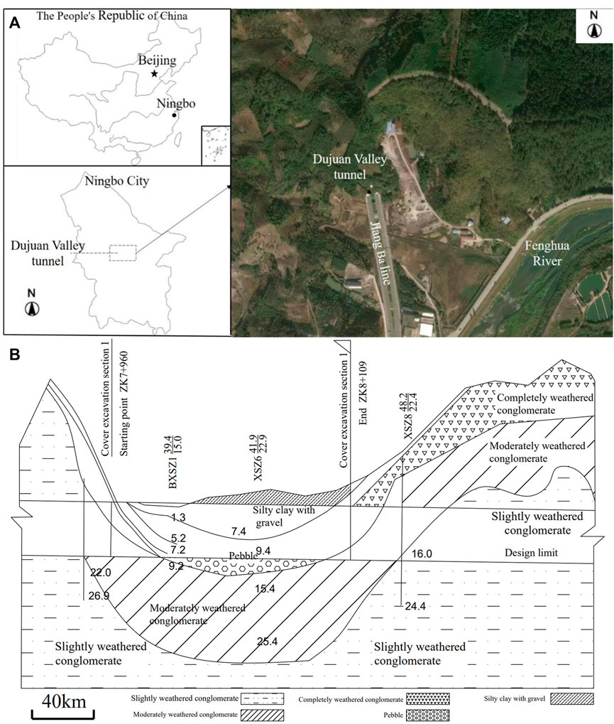
FIGURE 1. Engineering geology map of the tunnel location: (A) Plan of the tunnel; (B) A cross-section view of the tunnel.
A tunnel was built in Fenghua City, which has a total length of nearly 300 m and consists of three shallowly buried sections, all located in the valley alluvium. The excavation area of the tunnel is located in a geotechnical layer mainly composed of silty sandy soil and medium weathered conglomerate of slope alluvium, and it is a shallow buried tunnel. The stress distribution in the surrounding rock and the deformation of the lining during the construction of shallow buried tunnels are more complex, resulting in a more complex deformation pattern of the surrounding rock during tunnel construction. Existing tunnel construction methods are the drilling-blasting method, shield method, and cut and cover method (Yuan and Zhan, 2019; Han et al., 2020). The different tunnel construction methods are shown in Figure 2. The drilling-blasting method includes the full face excavation method, benching tunneling method, a center diaphragm, a cross diaphragm and double-side heading method. It is mainly applicable to the construction of mountain tunnels and requires oversupport before construction (Giovanni, 2016; Tang et al., 2019; Cao et al., 2021; Chen et al., 2021). The shield method is mainly applied to the construction of urban subways (Kazuhito et al., 1999). Zhu characterized the deformation of the rock in front of a tunnel under different ground stress soft rock conditions through model tests (Zhu et al., 2022). Zhang studied the construction method of large sections of shallowly buried tunnels and determined the method of construction conversion (Zhang et al., 2022). The cut and cover method includes two structural forms: one is a rectangular cross section, mainly used for the construction of urban subway stations; the other is a five-centered circle cross section, mainly used for mountainous tunnels (Kazuhito et al., 1999; Xiao et al., 2018). Considering the actual geological conditions, the cut and cover method (with a five-centered circle cross section) was finally selected as the construction method for this tunnel.
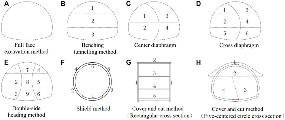
FIGURE 2. Cross-sectional models for different tunnel construction method: (A) Full face excavation method; (B) Benching tunnelling method; (C) Center diaphragm; (D) Cross diaphragm; (E) Double side heading method; (F) Shield method; (G) Cover and cut method (Rectangular cross section); (H) Cover and cut method (Five-centered circle cross section).
To construct a shallow buried section of a mountain tunnel by the cut and cover method, the buried depth h of the tunnel is less than the boundary depth Hp of the shallow tunnel, and the surface of the backfill soil can be regarded as the horizontal plane after pouring the covered arch.
The simplified geometric model of the bearing force of the covered arch in the shallow buried section of the mountain tunnel is shown in Figure 3. The geometric parameters in the model satisfy the following relations:
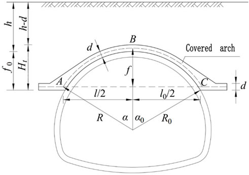
FIGURE 3. Geometric model of covered arch for shallow-buried section of mountain tunnel
In the formula, Hp is boundary depth of shallow buried tunnel; h is tunnel depth; f is the vertical distance from the centerline of the covered arch foot to the centerline of the arch roof, that is, the vector height of the stress analysis model of the covered arch; f0 is the vertical distance from the bottom of the covered arch foot to the top and bottom surface of the covered arch; R is the arc radius of the covered arch centerline; R0 is the arc radius inside the covered arch; d is the thickness of the covered arch; α is the center angle corresponding to the half arc of the covered arch centerline; and α0 is the center angle corresponding to the half arc inside the covered arch. l is the calculated span of the covered arch, that is, the horizontal distance between the centerlines at the arch foot on both sides of the covered arch. In addition, l0 is the net span of the covered arch, and h is the vertical distance from the bottom of the arch roof (that is, the top surface of the tunnel arch roof) to the ground.
Considering the anchoring effect of the arch foot anchor, horizontal interfacial friction and the restraining effect of the soil mass on both sides, the arch of the shallow buried section of the mountain tunnel can be simplified as a circular hingeless arch (Song and He, 2018).
The arch is subject to overlying backfill load q, static load qc and horizontal lateral pressure e of rock and soil on both sides. The simplified stress analysis model is shown in Figure 4A. Then, the formulas for calculating the external load borne by the arch are:
where h is the vertical distance from the inside of the vault to the ground, γ is the unit weight of the overlying backfill of the covered arch, γc is the concrete unit weight of the covered arch, Ht is the vertical distance from the bottom of the covered arch foot to the arch roof of the covered arch, and φc is the internal friction angle of the fill in the upper part of the covered arch.
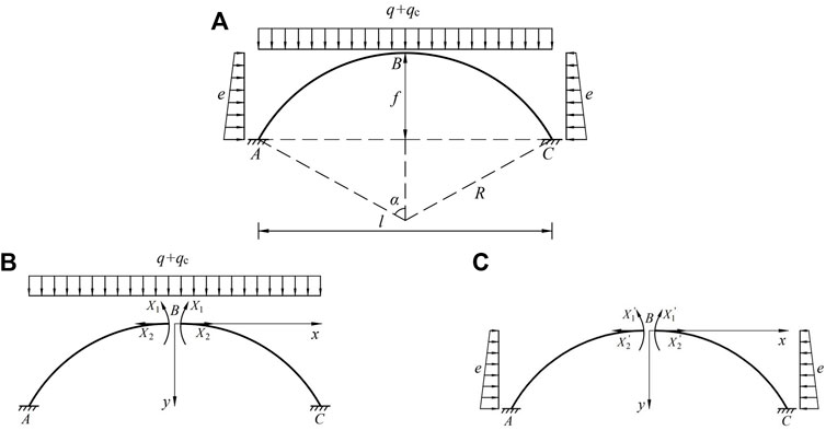
FIGURE 4. Internal force analysis model of covered arch: (A) Action of all loads; (B) Vertical load action; (C) Horizontal load action.
The structural mechanics method can be used to calculate the internal force of the covered arch and perform the stability calculation (Long et al., 2012).
The surface slope of the backfill after the construction of the covered arch can be nearly horizontal within the calculation range. Thus, the horizontal side pressures on the left and right sides of the covered arch are equal. As the stress of the covered arch along the longitudinal direction of the tunnel agrees with the assumption of plane strain, the unit length of the arch along the longitudinal direction of the tunnel is adopted for analysis. Figures 4B, C show the internal force analysis model of covered arch under the separate action of two directional loads.
When the internal force of the covered arch is solved by the structural mechanical force method, the effects of the bending moment term, axial force term and shear term on the internal force coefficient and the external load free term of the force method equation should be considered at the same time because of the partial working conditions
The internal forces of the arch vault and the arch foot under the action of vertical load
where
The above solution process is the internal force calculation method of the arch vault and arch foot in the shallow buried section of the mountain tunnel established in this paper. When using this method for designing covered supports or evaluating stability, the safety control standard is determined according to the strength of the arch material.
According to the stress analysis of the arch structure, it can be seen that both bending and compression deformation of the covered arch will occur under the action of the overlying vertical load and horizontal lateral load, and the safety control points are arch foot A and arch roof B.
According to the theory of material mechanics, the normal stress on the most vulnerable section can be obtained by using the superposition principle. According to the theory of material mechanics,
where
Thus far, a simplified calculation method of the internal force of covered arches in shallow buried sections of mountain tunnels under vertical loads and horizontal lateral loads has been established. This facilitates the optimization of the design and stability evaluation of covered arch structures. In addition to the overall stability of the covered arch meeting the requirements of the tensile strength of its own structure, it should be ensured that the bearing capacity and stability of the arch foot of the covered arch meet the requirements.
For the covered arch foot of the shallow buried section to meet the bearing capacity requirements, it is necessary to design the arch foot as a spread foundation, that is, the horizontal direction has a certain extension width b. Thus, the internal force generated by the vertical load of the covered arch and the horizontal lateral load at point A of the arch can be decomposed into the vertical force VA, the horizontal force HA and the bending moment MA, as shown in Figure 5. The equivalent vertical force VD, horizontal force HD and bending moment MD at the center point D of the arch are as follows:
where G is the sum of the arch foot foundation and the self-weight of the overlying backfill; b1 is the horizontal distance corresponding to the oblique section of point A of the arch, and b1 = l/l0.
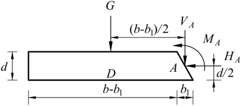
FIGURE 5. Mechanical analysis model of covered arch foundation.
According to the method of calculating the foundation bearing capacity, it can be seen that when the eccentricity of the foundation is
where A0 is the bottom area of the spread foundation of the covered arch foot, and A0 = b when calculating the unit width; W0 is the bending section coefficient of the spread foundation of the covered arch foot, and the unit width is
To ensure that there is no tensile stress between the arch foot of the covered arch and the soil and to reduce the design width of the foundation, Pmin should be greater than zero, and the allowable bearing capacity of the soil at the bottom of the foundation should be less than 1.2 times [fa]. [fa] can be obtained by modifying the depth and width according to the geological survey report.
To effectively transfer the external load borne by the covered arch to the arch foot spread foundation, section expansion is usually carried out at points A and C of the covered arch foot, that is, to smooth the transition section between the covered arch and the arch foot, as shown in Figure 6.
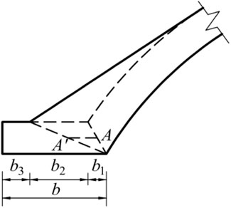
FIGURE 6. Geometric model of smoothing structure of arch.
After the smooth treatment of the arch foot, the position of the joint force of the arch foot will change from point A to point A, and the eccentricity from VA to the center of the foundation will be reduced from
In addition to meeting the requirements of vertical bearing capacity, the horizontal anti-slippage resistance of the spread foundation of the covered arch foot should also meet the design requirements. According to the standard calculation to check the anti-slip stability of the pier and foundation, it can be seen that the anti-slippage coefficient K should meet the following requirements:
where μ is the friction coefficient between the bottom surface of the foundation and the soil, which can be determined according to the test; fv is the shear strength of the anchor or grouting steel pipe at the base of the arch foot; and As is the sum of the cross-sectional area of the anchor or grouting steel pipe at the bottom of the spread foundation of the covered arch foot in the calculated unit width.
The spread foundation of the covered arch foot needs to meet the requirements of vertical settlement and deformation on the basis of the vertical and horizontal bearing capacity. For the covered arch structure, it is necessary to ensure that the arch foot foundation on both sides does not generate differential settlement before the settlement is controlled. Anchors or grouting steel pipes designed to ensure the anti-sliding stability of the spread foundation of the covered arch foot can effectively reduce foundation settlement.
The settlement calculation of the footing foundation does not take into account the influence of the free surface within the excavation in the tunnel construction. The concrete calculation process is not explained in detail in this paper.
Thus far, based on the structural mechanics analysis method and foundation design theory, the bearing deformation analysis method of the covered arch supporting structure in the shallow buried section of a mountain tunnel is established, which can be used to evaluate the support design of the covered arch or the stability of the existing schemes.
To further discuss the influence of different buried depths, heights, spans and thicknesses of the covered arch, geometric sizes of the arch foot spread foundation and soil parameters on the bearing deformation characteristics of the covered arch and to create a general design reference, it is necessary to use the above method to analyze the sensitivity of the bearing deformation characteristics of the covered arch supporting structure.
In this study, we mainly analyze the influence of the following factors on the bearing deformation characteristics of covered arches: tunnel buried depth h, arch rise f, inner circular angle 2α0, radius R0, concrete strength grade, arch foot width b, allowable foundation bearing capacity and degree of smoothing.
Although the deformation characteristics of the covered arch should focus on the differential settlement of the arch feet on both sides, the general bearing performance of the soil at the bottom of the arch-foot spread foundation is better for mountain tunnels. Thus, the anchor rod or the grouting steel pipe reinforcement measures adopted to meet the bearing requirements will further reduce the compression characteristics of the soil body. In such a case, the settlement deformation of the arch-foot spread foundation is usually small, and there is no obvious difference in deformation.
For special geological conditions, there may be differences that need to be calculated and analyzed. Due to paper length restrictions, the influence of various factors on the deformation characteristics of the covered arch and its arch foot is not discussed here.
The key control parameters of the covered arch design are the thickness of the covered arch, the center angle or arch rise, the width of the arch foot and the width of the smooth transition zone. In this study, the established analysis method is used to focus on the following cases to discuss the influence of each factor on the above parameters. The cover arch calculation parameters are shown in Table 1.
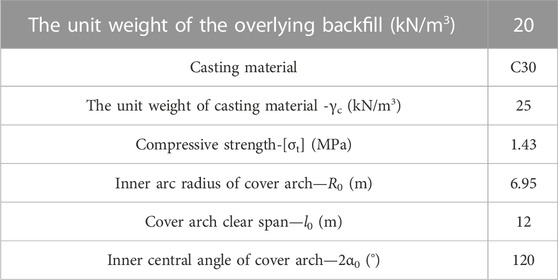
TABLE 1. Cover arch calculation parameters.
The thickness d of the covered arch is closely related to the rise f of the covered arch and the buried depth h of the tunnel. When the buried depth h of the tunnel is 2 m, 6 m, 10 m, 14 m and 18 m, the variation in the minimum safe thickness d of the covered arch with the rise f of the covered arch can be obtained according to the method of calculating the internal force of the covered arch, as shown in Figure 7. In the process of changing the rise f of the covered arch, the net span l0 of the covered arch remains unchanged, that is, the covered arch is not in complete contact with the tunnel lining, as shown in Figure 8A. In addition, there is another case in the process of changing the rise f of the covered arch; that is, the center of the arc of the covered arch remains unchanged, its inner center angle α0 changes, and the covered arch is in complete contact with the tunnel lining, as shown in Figure 8B. The calculation results corresponding to this working condition are shown in Figure 9.
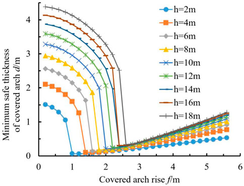
FIGURE 7. Relationship between thickness and covered arch rise with different tunnel depth (case 1)
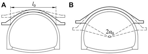
FIGURE 8. Calculation condition with different covered arch rises: (A) The span of covered arch is not changed; (B) The center of the covered arch is unchanged.

FIGURE 9. Relationship between thickness and covered arch central angle with different tunnel depth (case 2)
As seen from Figure 7, when the buried depth h of the tunnel is taken as a value between 2 and 18 m, the minimum safe thickness d of the covered arch decreases first and then increases with the increase in the covered arch rise f, and the rate of decrease in the early stage is greater than the rate of increase in the later stage. When the buried depth h of the tunnel increases from 2 m to 12 m (the Hp of the two-lane tunnel is approximately 12 m), the minimum safe thickness d of the covered arch increases from 7 cm to 24 cm, and the corresponding covered arch vector height f increases from 1 m to 2.2 m.
In addition, in working condition one shown in Figure 8A, when the tunnel is excavated, the soil mass on the inner side of the covered arch foot will collapse so that a cavity exists between the covered arch and the tunnel supporting structure, and the soil body can be backfilled after the soil is collapsed; otherwise, the combined bearing of the covered arch and the tunnel supporting structure is not favorable.
When the burial depth of the tunnel is 12 m, the minimum safe thickness d of the covered arch is 24 cm, and the rise f is 2.2 m. If the rise of the covered arch is increased to 3.44 m, the safe thickness d of the covered arch is 0.51 m, and the inner center angle of the covered arch is 2α0=120°. In this case, the covered arch and the tunnel support structure are in complete contact, as shown in Figure 8B, illustrating working condition 2. Although the thickness d of the covered arch is more than doubled, the combined bearing capacity of the covered arch and the tunnel support structure will be greatly improved. Therefore, the design scheme corresponding to working condition two is preferred in the design of covered arch supports.
Figure 9 shows that when the tunnel depth is less than 14 m, the minimum safe thickness d of the covered arch increases with the increase in the inner center angle 2α0, and the rate of increase of the minimum safe thickness d increases with the increase in the inner center angle 2α0.
When the buried depth of the tunnel is greater than or equal to 14 m, the minimum safe thickness d of the covered arch decreases at first and then increases with the increase in the inner center angle 2α0 of the covered arch, and there is the optimal center angle of the covered arch and its corresponding minimum safe thickness.
In addition, if the buried depth of the tunnel is h=18 m and the inner center angle of the covered arch is 2α0 = 120°, the minimum safe thickness d of the covered arch is 0.55 m, which is smaller than that of the shallow buried section recommended in the highway tunnel design code.
Reducing the inner center angle of the covered arch 2α0 can reduce the span of the arch l0, reduce the minimum safe thickness d of the covered arch and reduce the project cost. However, the foundation will gradually shift to the centerline of the tunnel, and its stability will be greatly affected by the empty surface produced by the excavation of the lower step during construction of the tunnel. Therefore, the inner center angle 2α0 of the covered arch should not be too small.
In contrast, with an increase in the inner center angle 2α0, the minimum safety thickness d of the covered arch will increase at an accelerating rate and the construction cost will increase, but the stability of the foot of the covered arch can be enhanced.
In conclusion, for shallow buried sections of mountain tunnels, the covered arch should be in full contact with the tunnel support structure. The inner circle center angle 2α0 is recommended to be 120°, and the thickness of the covered arch can be selected between 0.3 m and 0.6 m according to the buried depth of the tunnel.
The thickness d of the covered arch is related not only to the rise of the covered arch f and the inner circular center angle 2α0 but also to the radius R of the covered arch; that is, d is related to the span determined by the sidewalk and the driveway of the tunnel. This section mainly discusses the tunnel design conditions corresponding to radii R of 6 m, 7 m and 8.5 m. When the center angle of the inner circle is 110°, 120° and 130°, the variation in the minimum safe thickness d of the covered arch with the buried depth h of the tunnel is shown in Figure 10.
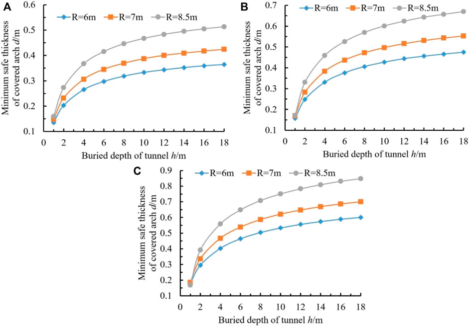
FIGURE 10. Relationship between thickness and tunnel depth with different covered arch radius: (A) 2α0 = 110°; (B) 2α0 = 120°; (C) 2α0 = 130°.
Figure 10 shows that regardless of the values of the central angle 2α0 of the inside of the covered arch and the radius R of the covered arch, the minimum safe thickness d of the covered arch increases with increasing tunnel depth h, and its rate of increase gradually decreases and eventually reaches a stable value.
With a larger inner circle center angle 2α0, the minimum safety thickness d required by the covered arch with the same radius R is larger, the maximum safety thickness d of the covered arch corresponding to the increase in the depth h of the same tunnel is greater, and the minimum safety thickness d must be larger to achieve stability.
In addition, when 2α0=110°, the minimum safe thickness d of the covered arch is less than 0.6 m regardless of the radius R of the covered arch and the buried depth h of the tunnel. When 2α0=120° and h <12 m, the minimum safe thickness d of the covered arch is also less than 0.6 m.
When 2α0 = 130°, the minimum safe thickness d of the covered arch varies greatly with changes in the radius R of the covered arch and the buried depth h of the tunnel.
Therefore, when designing the shallow buried section (h<12 m) of a mountain tunnel (i.e., 2R =12–17 m) with 2–3 one-way lanes, it is also recommended for the inner circular angle 2α0 of the covered arch to be 120°, and the maximum design thickness of the covered arch should not be greater than 0.6 m, which is the same as the conclusion of Section 3.1.
The thickness d of the covered arch is related not only to the geometric size of the covered arch but also to the material strength of the covered arch, that is, the concrete strength grade. Figure 11 shows the change in the minimum safe thickness d of the covered arch with the buried depth h when the concrete strength grade of the covered arch is C25, C30, C35 and C40.
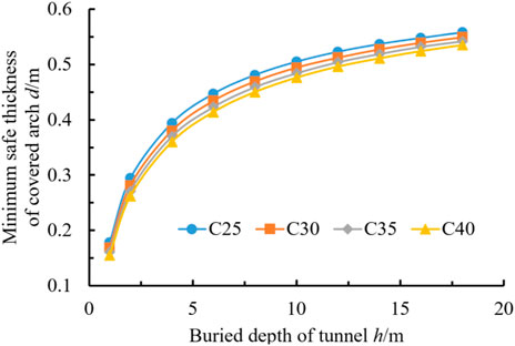
FIGURE 11. Relationship between thickness and tunnel depth with different concrete strength grade.
According to Figure 11, the minimum safety thickness d of the covered arch increases with increasing depth h of the tunnel regardless of the type of concrete used for the covered arch, but the rate of increase gradually decreases. In addition, the effect of the concrete strength grade on the minimum safety thickness of the covered arch is small. If the depth of the tunnel is h=8 m, when the concrete strength is raised from C25 to C40, the minimum safety thickness of the covered arch is reduced from 0.48 m to 0.45 m.
Therefore, it is not necessary to use high-grade concrete in shallow-buried sections of mountain tunnels. Instead, low-grade concrete can be used, along with appropriately increasing the thickness of the covered arch and controlling the pouring quality of the concrete, which can also ensure that the bearing capacity of the covered arch meets the requirements.
The stability and safety of the covered arch structure should not only enable the covered arch to bear the self-weight of the overlying backfill body but also ensure that the arch and arch feet can effectively transfer the internal force of the covered arch to the foundation through the enlarged foundation; that is, the design size of the enlarged arch foot foundation should meet the foundation bearing capacity requirements.
When the covered arch thickness d is 0.6 m and the characteristic value fa of the modified foundation bearing capacity is 500 kPa, 1,000 kPa, 1,500 kPa and 2,000 kPa, and the variation of the minimum safe width b of the covered arch foot spread foundation with the tunnel buried depth h is shown in Figure 12.
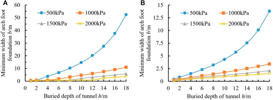
FIGURE 12. Relationship between width and bearing capacity with different tunnel depth: (A) Do not consider smooth transition of arch foot; (B) Considering smooth transition of the arch foot (b3=0.5 m).
It can be seen from Figure 12 that, whether the foundation bearing capacity fa is high or low after modification, the minimum width b of the arch foot spread foundation increases with the increase in the buried depth of the tunnel, and the smaller the foundation bearing capacity fa is, the higher the rate of increase of the minimum width b of the enlarged arch foot base.
In addition, if the transition section of the covered arch and arch foot is smoothed (b3=0.5 m), the minimum width b of the arch foot spread foundation will be greatly reduced under the same working conditions, such as when fa=1,000 kPa and h=8 m, the minimum width b of the arch foot enlarged foundation is 3.32 m and 1.43 m, respectively, and the minimum widths of the two conditions are quite different.
If the foundation bearing capacity fa is increased from 1,000 kPa to 1,500 kPa without smoothing treatment, the minimum width b of the arch foot spread foundation will be reduced from 3.32 m to 0.90 m.
Therefore, in the design of a covered arch foot spread foundation, the arch foot should be placed on the soil layer with a high foundation bearing capacity or improved by foundation treatment, and the transition section between the covered arch and arch foot should be smoothed. The smoothing should reduce the size of the arch foot and considerably expand the designed width of the foundation. The total construction costs of such a design are lower.
According to the results of the analysis in Section 4.4, it can be seen that the spread foundation width b by the arch foot is related not only to the buried depth h of the tunnel and the modified bearing capacity fa of the foundation but also to the degree of smoothness of the transition section. In this study, the residual width b3 after smoothing of the arch foot foundation is used.
When the thickness of the covered arch is 0.6 m and the modified characteristic value of foundation bearing capacity fa=1,000 kPa, for different tunnel depths, the variation of the minimum safe width b of the covered arch foot with the residual width b3 after smoothing is shown in Figure 13.
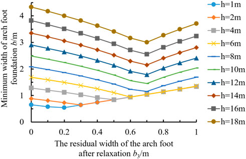
FIGURE 13. Relationship between thickness and width with different tunnel depth.
When the tunnel burial depth h changes from 1 to 18 m, the minimum safe width b of the spread foundation decreases first and then increases with increasing remaining width b3. b1 remains constant due to the thickness d of the arch, the inner center angle 2α0 and the radius of arc R. A reasonable combination of the residual width b3 and the width b2 of the smooth transition section will minimize the spread foundation width b.
When h increases from 1 m to 8 m, the minimum safe width b increases from 0.54 m to 1.15 m, the corresponding residual width b3 increases from 0.2 m to 0.7 m, and the width b2 of the smooth transition section increases from 0 m to 0.11 m, while b1 remains unchanged at 0.34 m. When h > 8 m, the minimum safety width b increases with increasing tunnel depth h, while the residual widths b3 and b1 remain unchanged at 0.7 m and 0.34 m, respectively.
Therefore, when the buried depth of the tunnel is less than 8 m, the optimal combination of the width b2 of the smooth transition section and the remaining width after smoothing b3 should be optimized for the design of the enlarged foundation with the arch foot of the covered arch, and the width b of the foundation should be minimized to satisfy the bearing capacity.
When the buried depth of the tunnel is more than 8 m, the residual width after smoothing b3 of the arch foot should be set at 0.7 m, and the width b2 of the smooth transition section can be determined by calculation. Then, the spread foundation width b of the arch foot is obtained.
Thus far, the influence of the tunnel depth h, the height of the rise f, the inner center angle 2α0, the radius R0, the width of the arch foot b and the degree of smoothing on the bearing characteristics of the covered arch are obtained. According to the results of each factor analysis, the following conclusions can be made:
For the design of the covered excavation and support for a shallow buried section of a mountain tunnel with a buried depth h<12 m, the covered arch should be in full contact with the tunnel support structure, the inner round angle of the covered arch should not be less than 120°, the safety thickness d of the covered arch should be determined according to the specific buried depth and span of the tunnel, and the maximum thickness should not be more than 0.6 m.
The transition section between the covered arch and arch foot should be smoothed, and the thickness of the arch foot spread foundation can be the same as that of the covered arch. The width b should consider the reasonable combination of fa, smooth transition section width b2 and residual width b3 after smoothing and be determined through optimization analysis so that the design scheme of the covered arch support can minimize the construction cost and meet the requirements of bearing deformation.
The above is the method to design and optimize covered excavation supports for shallow buried sections of mountain tunnels established in this paper.
A typical designed section of the covered arch is shown in Figure 14. The buried depth h of the tunnel is 4 m, the thickness d of the covered arch is 0.6 m, the inner circle center angle 2α0 is 120°, the arc radius R is 7.25 m, the base width b of the arch foot foundation width b is 1.9 m, the smooth transition residual width b3 is 0.5 m, and the covered arch foot foundation is a cobble layer. The basic allowable value of the bearing capacity is 400 kPa, the foundation reinforcement is carried out by using a hollow grouting anchor rod of JiN4MDAzYTY7MjVAMC42 m, the anchor rod is connected with the arch foot spread foundation, and the foundation of the covered arch and the arch foot is cast by C30 concrete so that the steel arch frame supporting at the initial stage of the tunnel is formed into a ring. The I-shaped steel in the range of the covered arch is placed in the covered arch with a spacing of 0.6 m.
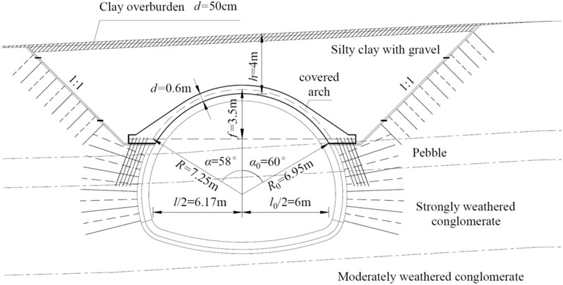
FIGURE 14. Typical design section of covered arch.
In the cut and cover method, the soil mold is built and the protective structure of the roof of the dark cave is constructed after a certain depth of open excavation. A hidden tunnel under the cover arch is constructed as a safety protection structure. According to the actual topographic and geological conditions of the shallow buried section of the Dujuan Valley tunnel, the construction of the cover excavation section is generally in the following order: construction of the temporary surface drainage system→excavation and protection of the slope and front slope→soil model construction and concrete pouring of the arch→back filling and green covering of the arch. A site construction diagram of covered excavation of a shallow-buried tunnel is shown in Figure 15.
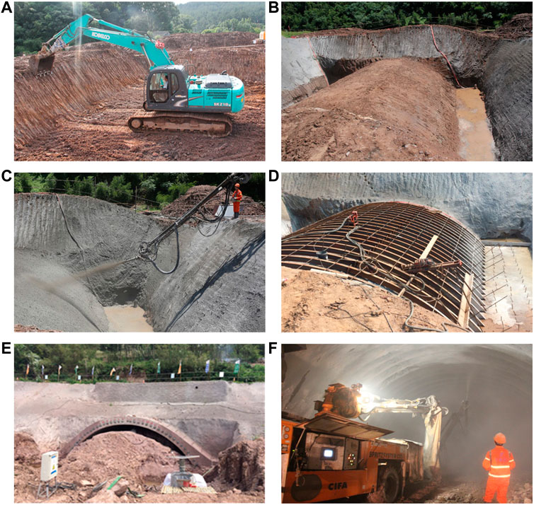
FIGURE 15. Site construction diagram of shallow-buried cover excavation section Ⅰ: (A) Slope excavation and dressing; (B) Schematic diagram of soil mold; (C) Soil arch hardening treatment; (D) I-beam installation and split screw installation; (E) Excavation of underground tunnel; (F) Initial shotcrete support.
The method was applied to the construction design of the Azalea Valley Tunnel of the Ningbo 309 Provincial Highway Relocation Project. The sensitivity of the bearing characteristics of the cover arch support structure was then determined. According to the sensitivity analysis, for the shallow buried section of the mountain ridge tunnel, the designed cover arch should be in full contact with the tunnel support structure, the inner circle angle is taken as 120°, the cover arch can be poured without high-grade concrete, and the concrete grade can be reduced by adjusting the thickness of the cover arch to a value between 0.3 and 0.6 m. The transition section between the cover arch and the foot of the arch should also be smoothed and eased, which reduces the foot of the arch to expand the design width of the foundation. These conclusions can be applied to the construction of other shallow buried tunnels.
Finally, the reasonableness of the excavation method is verified by the actual project. Based on the method established in this paper, when h = 4 m, d = 0.6 m, R = 7.25 m, and 2α0 = 120°, the minimum safe thickness d is 0.38 m, while the design thickness of the section covered arch is 0.6 m, which meets the bearing capacity requirements of the covered arch. In addition, the steel arch frame initially lined in the tunnel will be poured on the inside of the covered arch during the construction of the covered arch, which will further increase the bearing stability of the covered arch. If the basic allowable value of the bearing capacity of the arch foot is 400 kPa, the width b of the arch foot should be greater than 1.75 m, and the width b2 of the smoothed transition section and the residual width b3 after smoothing should be 0.81 m and 0.6 m, respectively. Although 1.75 m is smaller than the design value b = 1.9 m of the project, it is safe. If the foundation is strengthened with a hollow grouting anchor rod, the basic allowable value of the foundation bearing capacity can be increased to 1,200 kPa; then, b = 0.8 m, b2 = 0.06 m, and b3 = 0.4 m, which is smaller than the parameters corresponding to the section design scheme, which indicates that the design parameters of the arch foot spread foundation meet the requirements of bearing capacity stability. In addition, the connection between the anchor rod and arch foot will increase the ability of the foundation to resist forces applied horizontally, and its safety factor K = 1.6 > 1.3, which meets the design requirements.
Thus, the design parameters of the spread foundation of the section covered arch and arch foot meet the requirements of safety and stability. Additionally, the maximum vertical settlement monitoring value of the inner apex of the section covered arch being 7 mm in the actual tunnel excavation process shows that the design parameters of the section are safe and feasible. This indirectly verifies the rationality of the method and analysis results established in this paper.
To obtain a new design method for excavation and support of shallow buried sections of mountain tunnels, the structural mechanics method is used to carry out the force analysis of the arc-shaped unhinged arch. The specific results are as follows:
(1) A simplified analysis model of a circular arc-shaped unhinged arch to calculate the bearing force of a covered arch in a shallow buried section of a mountain tunnel is proposed, and the internal force analysis method of a covered arch is established by using the structural mechanics method. Then, the method to calculate the safe thickness of a covered arch supporting structure is proposed. Considering the smooth transition between the covered arch and arch foot, the design and stability analysis method of the covered arch foot spread foundation is constructed, and the design method of the covered arch support in the shallow buried section of the mountain tunnel is obtained.
(2) This article describe the influence of the following factors and others on the bearing characteristics of the cover arch support structure: tunnel burial depth, cover arch sag height, inner central angle, radius, concrete strength grade, arch foot width, allowable foundation bearing capacity and degree of smoothness.
(3) It is proposed that the cover arch should be designed to be in complete contact with the tunnel supporting structure, the thickness of the cover arch should not be greater than 0.6 m, the inner central angle should not be less than 120°, and a transition section should be set between the cover arch and the arch foot. The optimal design principles of the cover arch and the arch foot foundation of the shallow buried section of the mountain tunnel are obtained.
The datasets presented in this study can be found in online repositories. The names of the repository/repositories and accession number(s) can be found in the article/supplementary material.
JC: Writing—original draft, conception, data analysis, and data collection. YJ-Z: Review of the manuscript and directed the research for this paper. HX: Contributed to the theoretical analysis in this paper and directed the research for this paper.
National Natural Science Foundation of China, No.51878071, No.52178416 Science and Technology Project of Ningbo Municipal Transportation Commission, No.201503. Changsha University of Science and Technology innovative projects of civil engineering key discipline, No.18ZDXK08.
The authors declare that the research was conducted in the absence of any commercial or financial relationships that could be construed as a potential conflict of interest.
All claims expressed in this article are solely those of the authors and do not necessarily represent those of their affiliated organizations, or those of the publisher, the editors and the reviewers. Any product that may be evaluated in this article, or claim that may be made by its manufacturer, is not guaranteed or endorsed by the publisher.
The Supplementary Material for this article can be found online at: https://www.frontiersin.org/articles/10.3389/feart.2023.1092928/full#supplementary-material
Bae, G. J., Lee, S, W., and Lee, G. P. (2004). A numerical study on behavioural characteristics of cut and cover tunnels. Tunn. Undergr. Space Technol. 19, 482–483. doi:10.1016/j.tust.2004.02.082
Cao, S., Xie, Y., Tang, W., Wang, W., Zhou, Q., and Guo, A. (2021). Research on construction methods for ultralarge y-shaped tunnel sections. Math. Problems Eng. 2021, 1–9. doi:10.1155/2021/9969208
Chen, C-S., and Liu, Y-C. (2006). A methodology for evaluation and classification of rock mass quality on tunnel engineering. Tunn. Undergr. Space Technol. 22, 377–387. doi:10.1016/j.tust.2006.10.003
Chen, Z., Wang, Z., Su, G., Gao, S., and Hu, X. (2021). Construction technology of micro bench cut method for weak rock tunnel with high in-situ stress. Geotechnical Geol. Eng. 40, 1407–1415. doi:10.1007/s10706-021-01971-0
Giovanni, B. (2016). Full-face excavation of large tunnels in difficult conditions. J. Rock Mech. Geotechnical Eng. 3, 294–303. doi:10.1016/j.jrmge.2015.12.003
Han, H., Fukuda, D., Liu, H., Salmi, E. F., Chan, A., Liu, T., et al. (2020). Fdem simulation of rock damage evolution induced by contour blasting in the bench of tunnel at deep depth. Tunn. Undergr. Space Technol. 103, 103495. doi:10.1016/j.tust.2020.103495
Holmes, G., Roscoe, H., and Chodorowski, A. (2006). Construction monitoring of cut and cover tunnels. Geotech. Eng. 158, 187–196. doi:10.1680/geng.2005.158.4.187
Hwang, J. H. (2009). Numerical analyses for mechanical behavior of cut-and-cover tunnel with precast arch type. J. Korean Tunn. Undergr. Space Assoc. 11, 315–325.
Kazuhito, K., Kenichi, S., Hirokazu, A., Toshiyuki, H., and Malcolm, D. B. (1999). Finite element modelling of excavation and advancement processes of a shield tunnelling machine. Soils Found. 3, 37–52. doi:10.3208/sandf.39.3_37
Lee, S., Bae, G., and Choi, C. (2004). Reduced-scale model tests for cut and cover tunnels subjected to eccentric load. Tunn. Undergr. Space Technol. 19, 481. doi:10.1016/j.tust.2004.02.081
Li, S., Han, G., Ho, I. H., Ma, L., Wang, Q., and Yu, B. (2020a). Experimental and numerical analyses for Earth pressure distribution on high-filled cut-and-cover tunnels. KSCE J. Civ. Eng. 24, 1903–1913. doi:10.1007/s12205-020-1693-7
Li, S., Ho, I. H., Ma, L., Yao, Y., and Wang, C. (2019a). Load reduction on high-filled cut-and-cover tunnel using discrete element method. Comput. Geotechnics 114, 103149. doi:10.1016/j.compgeo.2019.103149
Li, S., Jianie, Y., Ho, I. H., Ma, L., and Wang, C. (2021). Evolution of load reduction for high-filled cut-and-cover tunnels subjected to soil creep. Int. J. Geomechanics 21. doi:10.1061/(ASCE)GM.1943-5622.0002089
Li, S., Ma, L., I-Hsuan, Ho., Wang, Q., Yu, B., and Zhou, P. (2020c). Method to estimate lateral Earth Pressure on high-filled cut-and-cover tunnels. KSCE J. Civ. Eng. 24, 975–987. doi:10.1007/s12205-020-1060-8
Li, S., Ma, L., I-Hsuan, Ho., Wang, Q., Yu, B., and Zhou, P. (2019b). Modification of vertical Earth pressure formulas for high fill cut-and-cover tunnels using experimental and numerical methods. Math. problems Eng. 19, 1–19. doi:10.1155/2019/8257157
Li, S., Yao, Y., Ho, I. H., Ma, L., Wang, Q., and Wang, C. (2020b). Coupled effect of expanded polystyrene and geogrid on load reduction for high-filled cut-and-cover tunnels using the discrete element method. Int. J. Geomechanics 20, 04020052. doi:10.1061/(asce)gm.1943-5622.0001683
Long, Y. Q., Bao, S. H., and Yuan, S. (2012). Special course on structural mechanics II. Beijing: Higher Education Press.
Shariatmadari, N., Chaichi, P., and Moazami, M. (2006). The survey of ground surface settlement caused by cut and cover tunnel excavation in Tabriz subway. Tunn. Undergr. space Technol. 21, 455. doi:10.1016/j.tust.2005.12.093
Song, C. Y., and He, W. G. (2018). Design analysis of superimposed bearing arch structure of large span tunnel in up-soft and low-hard rock stratum. Mod. Tunn. Technol. 55, 17–26. doi:10.13807/j.cnki.mtt.2018.01.003
Tang, X., Wang, Y., and Li, Y. (2019). Numerical researches on the optimization of construction methods in tunnels with super large section. IOP Conf. Ser. Earth Environ. Sci. 304, 032024. doi:10.1088/1755-1315/304/3/032024
Wang, M. (2010). Tunneling and underground engineering technology in China. Beijing China; People's Communications Press.
Wang, S. H., Wang, C. L., and Xie, Q. T. (2010). Reinforcement strategies of construction in shallow-huried tunnel entrance using pipe-roofing method in valley. Chin. J. Rock Mech. Eng. 29, 1457–1466.
Williams, R. L., and Chalmers, G. (2000). Recent developments in the design of cut and cover construction of railway tunnels and stations. Railw. Technol. 21st Century, 326–343. doi:10.3316/informit.494661841985724
Xiao, X., Chen, J. J., Li, M. G., and Wang, J. H. (2018). Field monitoring of an existing cut-and-cover tunnel between two large-scale deep excavations. J. Aerosp. Eng. 31 (6), 04018082. doi:10.1061/(ASCE)AS.1943-5525.0000851
Xu, C. M., and WuWu, L., (2015). Instability mechanism and reinforcement technology of open cut section of high speed railway tunnel. Mod. Tunneling Technol. 52, 126–134. doi:10.13807/j.cnki.mtt.2015.06.019
Yao, Y., Sheng, L. I., Li, M. A., Wang, H., Bentian, Y. U., and Wang, C. (2020). Analysis on soil arching for unloading structure of high-filled cut-and-cover tunnel based on particle flow simulation. J. Railw. Sci. Eng. doi:10.19713/j.cnki.43-1423/u.T20190210
Yuan, D., and Zhan, W. (2019). Comparison of construction methods for shallow burial tunnel with soft rock and large span. IOP Conf. Ser. Earth Environ. Sci. 300, 022047. doi:10.1088/1755-1315/300/2/022047
Zhang, Z., Zhao, C., Peng, L., Zhang, X., and Lei, M. (2022). Research on the stability of shallow-buried large cross-section tunnel by construction method conversion. Front. Earth Sci. 10, 831169. doi:10.3389/feart.2022.831169
Keywords: shallow-buried sections of mountain tunnels, cut and cover method, supporting structure design method, sensitivity analysis, optimization design principle
Citation: Zhang Y-J, Cao J and Xu H (2023) A design analysis method and its application in the cover arch of cut-and-cover tunnels. Front. Earth Sci. 11:1092928. doi: 10.3389/feart.2023.1092928
Received: 08 November 2022; Accepted: 10 March 2023;
Published: 22 March 2023.
Edited by:
Xiaoli Liu, Tsinghua University, ChinaReviewed by:
Pengpeng Ni, Sun Yat-sen University, ChinaCopyright © 2023 Zhang, Cao and Xu. This is an open-access article distributed under the terms of the Creative Commons Attribution License (CC BY). The use, distribution or reproduction in other forums is permitted, provided the original author(s) and the copyright owner(s) are credited and that the original publication in this journal is cited, in accordance with accepted academic practice. No use, distribution or reproduction is permitted which does not comply with these terms.
*Correspondence: Hong Xu, eHVob25nQGNzdXN0LmVkdS5jbg==
Disclaimer: All claims expressed in this article are solely those of the authors and do not necessarily represent those of their affiliated organizations, or those of the publisher, the editors and the reviewers. Any product that may be evaluated in this article or claim that may be made by its manufacturer is not guaranteed or endorsed by the publisher.
Research integrity at Frontiers
Learn more about the work of our research integrity team to safeguard the quality of each article we publish.