 Jianjun Shi
 Xiaopeng Miao
 Haili Meng2
 Huaming An
95% of researchers rate our articles as excellent or good
Learn more about the work of our research integrity team to safeguard the quality of each article we publish.
Find out more
ORIGINAL RESEARCH article
Front. Earth Sci. , 07 July 2022
Sec. Geohazards and Georisks
Volume 10 - 2022 | https://doi.org/10.3389/feart.2022.884558
This article is part of the Research Topic Rock Landslide Risk Assessment, Stability Analysis and Monitoring for The Development of Early Warning Systems and Reinforcement Measures View all 24 articles
Reserved rock wall is usually used in blasting operation when one side has an important protection object. Rock wall demolition blasting was essentially a parallel double-free surface blasting; blasting is the ideal effect of casting a side fully broken rock mass, throwing, on the other side (protection) of rock mass at the injury status of “broken and do not come loose”; the minimum thickness of the rock wall last could hole to protect the width of side of the free surface, called the critical damage width. First, based on the theory of multi-boundary blasting, the relationship among the throwing effect, boundary condition, and charge quantity of parallel double-free surface blasting is expounded in this article. The model of equivalent sub-charge package was established to deduce the relationship of bilateral resistance lines, and the theoretical value of critical damage width was 2.05 W (minimum resistance line). Second, according to the rock wall demolition and blasting of the Yangtou station renovation project in the second line of Yuhuai, the critical damage width of 2.5 W was measured through a single row and hole-by-hole detonation field test. The results of study on critical damage width of parallel double-free surface blasting can provide theoretical guidance for similar projects.
Under the condition that one side has an important protection object, the blasting construction method of reserved rock wall is often adopted (Yang et al., 2010), that is, a rock wall of certain thickness is reserved on the side close to the protection object (Figure 1). The rock block blasting in the whole blasting area is divided into internal main rock block blasting and external rock wall demolition blasting. During blasting, the internal main stone is first exploded, and then the external rock wall is removed. The rock mass inside the rock wall is constructed by a conventional deep hole step control blasting method. When the inner rock mass of the rock wall is blasted, the rock wall, as a natural barrier, can prevent the lateral escape of the explosion pile, and at the same time, the rock wall can maintain a relative stability, avoiding the damage, stripping and rolling of slope rock block. In this way, the shielding effect of the reserved rock wall can reduce the difficulty of the main rock block blasting construction and the harm to the surrounding environment (Meng, 2015; Miao, 2020).
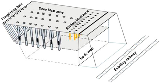
FIGURE 1. Schematic diagram of rock wall blasting.
Meng et al. (2012) used rock wall control blasting technology in the expansion project of Chongqing–Fuzhou Railway adjacent to the existing line, pointing out that the internal main blast area of the deep hole blasting the direction of the air front parallel to the direction of the existing line. This technology can effectively control the impact of flying rocks, rolling rocks, and blasting vibration on the existing line, and then put the safety control point of the whole project on the demolition of the reserved rock wall. The construction method of the rock wall becomes the key to ensure the safety of the adjacent protection objects (Meng, 2015).
In the process of reserved rock wall removal, Tang et al. (2019) used diamond rope saw to cut the reserved rock wall, and this method is similar to the mechanical removal by rock drill, which can effectively ensure the safety of existing railway lines or surrounding buildings. However, both of them have the disadvantages of high economic cost and slow construction progress, which are not suitable for large area promotion and use. In order to achieve convenient construction and economic and reasonable purposes, the use of blasting demolition of rock walls has become possible.
Reserved rock wall blasting is a kind of step blasting, but it also has its particularity. The main characteristics are as follows: 1) it is greatly affected by groove blasting in the early stage. Due to the large amount of clamps used in trench blasting, it is necessary to increase the single consumption of explosive and the ratio of drilling hole properly, but it cannot cause damage to the rock wall. 2) There are often important facilities around the explosion area that are needed to be protected. The collapse of blasting heap and the rolling stones generated by high steep slope during blasting and rock excavation are easy to damage the environment. The flying stones and vibration of blasting must also be strictly controlled. 3) The blasting area is long and the geological conditions vary greatly, so the blasting parameters must be constantly adjusted, and the blasting medium must be fully broken or disintegrated. 4) Rock wall with the main blasting area synchronization drop, rock wall blasting adopts precision deep hole loose blasting control or shallow hole blasting; the blasting area is covered with the protective and facade multivariate stereoscopic protection system of the comprehensive protection, and the gun head machine and high-power drivers to construction are arranged, to ensure that the protected objects are safe during the rock wall blasting (Guo and xue, 2015).
The blasting resistance line of rock wall demolition deviates from the protected object, which can effectively control blasting vibration and the harm of the flying rock (Tang et al., 2019). Rock wall demolition blasting strictly belongs to parallel double-free face multi-boundary blasting. The throwing effect at this time depends on two factors: boundary conditions and charge amount (Wang et al., 2008).To tie in with the construction, the side of the ideal casting blasting effect is a fully broken rock mass, casting, protect the rock on one side of the object to the “broken and not loose” (damage and do not break), the critical instability state, and it does not allow individual slungshot, both to ensure the safety of protection objects, and can easily remove the broken part of the stone. Due to the particularity of parallel double-free face blasting, the initiation of row-by-row and hole-by-hole must be adopted (Wang, 1992). If strengthening loose blasting is used to charge, the blasting effect only depends on the width from the last row of holes to the inner side of the rock wall, which is called the critical damage width.
Meng (2015) believed that when the stress wave reached the inner side of the rock wall, its strength should not be greater than the compressive strength of the rock mass, and the critical damage width should not be less than 1.5 times the minimum resistance line. Meng et al. (2012) found that the critical damage width was greater than two times the minimum resistance line in the cutting expansion project adjacent to the existing line of Yuan–Fuzhou Railway and Yang Lin (Yang et al., 2010) in the An Tuoshan remediation project.
Most of the previous determinations of critical damage widths come from engineering experience and lack a certain theoretical basis. Based on the multi-boundary blasting theory, an equivalent surcharge-package model was established to derive the relationship between parallel double-free surface resistance lines to determine the theoretical value of the critical damage width for rock wall demolition blasting. In addition, the minimum resistance line of 2.5 times of the critical damage width was determined based on the blasting of the rock wall of the Yangtou–Yuexing station renovation project of the Yuhuai 2 line, where the blasting effect of “broken but not scattered” unexploded rock was achieved after three blasts.
The multi-boundary condition refers to the boundary condition of micro-terrain, which belongs to the shape geometry condition compared with the horizontal boundary condition. Terrain changes not only affect the blasting effect but also affect the calculating blasting role within the scope of damage index and effective utilization of explosive energy (Huang, 2006).
According to the blasting efficiency and geological characteristics, the micro-terrain boundary conditions can be divided into horizontal boundary conditions, tilt boundary conditions, boundary conditions of convex multi surface free terrain and topographic boundary conditions of the concave pass, as shown in Figure 2. 1) The characteristic quantity of the tilt boundary condition is that the slope angle α ranges from 0 to 90°, and the general flat terrain is a special case of the slope boundary condition α = 0. 2) For boundary conditions of convex multi surface free terrain, general characteristics are on either side of the ridge slopes α1 and α2, (rock wall demolition blasting is the convex face more empty terrain, α1 and α2 approximate to 90°), through the study of hill facing more empty blasting, with energy distribution coefficient control medicine package location arrangement, usable slow lateral ground slope angle of the characteristics of representative face more empty terrain, and the multi-faced empty terrain can be converted into inclined boundary condition. 3) For topographic boundary conditions of the concave pass, the reciprocal of convex boundary condition can be approximated. In this way, the slope angle in the boundary conditions of multi-boundary blasting can be used as the basis of model calculation by the ground slope angle α, a characteristic quantity of slope boundary conditions.
a) Horizontal boundary condition,
b) inclined boundary condition,
c) convex multiple face empty boundary conditions, and
d) concave pass boundary condition.
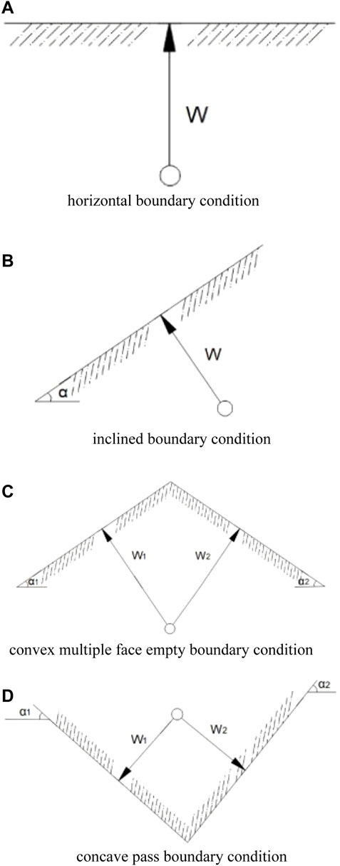
FIGURE 2. Classification diagram of boundary conditions.
In multi-boundary blasting, the blasting effect is measured by a throwing rate (E), which refers to the volume of rock thrown out as a percentage of the overall volume of rock being blasted, expressed in Eq. 1:
When the throw rate E = 27%, the throw rate is defined as the standard state. Hongqu Wang and Wenxue Gao (Gao and Liu, 2007) derived the calculation formula of multi-boundary blasting charge based on the principle of conservation of mechanical energy and functional balance, as shown in Eq. 2:
In the equation, K is the charge amount per cubic meter when forming a standard throwing funnel; W is the minimum resistance line length; and Fϕ(E,α) is the theoretical explosive package property index. Wang and Gao derived the theoretical explosive package property index as:
In the aforementioned equation, E is the throw rate; α is the natural ground slope; and f(α) is the throw factor, which is consistent with the meaning of the terrain coefficient; fϕ(α,E) is the terrain factor, which means the terrain is favorable, the effective utilization rate of explosive energy increases or the projectile volume increases, and the charge should be reduced, also known as the charge attenuation coefficient (Gao et al., 2010).
When explosive conversion coefficient e and plugging coefficient d are added, the theoretical calculation formula of multi-boundary blasting charge is as follows (Liu, 1999):
The aforementioned formula describes the inner relationship among the throwing effect, boundary condition, and charge amount. Q is the charge quantity, and the throwing effect is reflected by the throwing rate E, α can be used to describe the inclined boundary conditions of blasting rock and soil mass (horizontal boundary conditions, convex and concave boundary conditions can all be used as models for subsequent calculation).
The explosive amount of a multi-directional charge is decomposed into sub-charge directed by each surface, according to the proportion of the space resistance line of each surface, so that its blasting action and blasting parameters are equivalent to one-way charge, which is called equivalent sub-charge.
According to the equivalent sub-charge blasting energy distribution model and multi-direction group charge blasting energy distribution model, the following model is established for rock wall demolition blasting (double resistance line and double face blasting).Suppose a small cylindrical cartridge of equal diameter is set on the axis of a homogeneous, unequal radius, and infinite length thick-walled circle, and its volume is negligible compared with that of the thick-walled circle. Take a unit length from it, as shown in Figure 3. There is no problem of energy dissipation in the axis direction of the intercepted cylindrical charge of unit length, and the explosive energy can only spread evenly along the radial direction (resistance line direction) of the thick-walled circle, so that it is broken and generates speed. At this point, the momentum obtained by monomers on both sides (the throwing funnel of single concentrated charge blasting, the joint action area of adjacent charge blasting of single row unidirectional group charge blasting, and the action area of single unidirectional prolonged charge blasting, except for the end being thrown out of the body, are collectively called monomers) is equal to the impulse of explosive gas acting on the hole air cavity, as shown in Eq. 6.
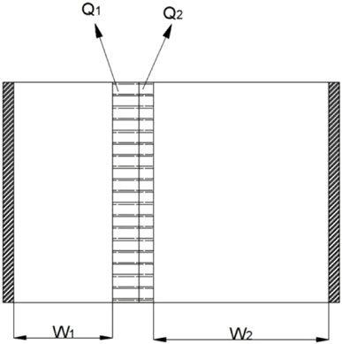
FIGURE 3. Model diagram of equivalent sub-charge package.
In the equation, v1 and v2 are the velocity of monomers on both sides, m1 and m2 are the mass of monomers on both sides, a is the radius of the gun hole, P is the pressure of the explosion gas, θ is the angle of the gun aperture toward the center of the circle, t is the action time, W is the minimum resistance line, and ρ is the density of rock mass. By combining Eq. 6 with Eq. 7, it can be obtained that the square of resistance line of monomer velocity on both sides is inversely proportional, as shown in Eq. 8.
Under the condition of double air surface (bilateral resistance line), the conventional strip charge was decomposed into two equivalent sub-charge packets, with the equivalent charge quantity of Q1 and Q2, respectively.
The monomer velocity formula is as follows (Gao et al., 2010):
In the equation, Kv is the velocity coefficient and V is the volume of monomer. Combining Eq. 8 with Eq. 9,
According to Eq. 10,
In the theoretical calculation formula of multi-boundary blasting charge, let
Then the formula for calculating the amount of charge on multiple surfaces can be simplified as (Liu and Gao, 2006):
The rock wall demolition blasting belongs to convex double-sided aerial terrain, and α1 and α2 are approximately 90°. After determining the energy distribution of both sides of the sub-charge through the equivalent sub-charge package model, Eqs 10, 12 are jointly solved as follows:
It can be seen from the analysis that the inner relationship among the throwing effect, boundary conditions, and charge amount of throwing blasting can be quantitatively described by Eq. 12 for the calculation of charge amount of multi-boundary blasting. Eq. 14 can be used to further quantitatively determine the relationship between the resistance lines on both sides of double-free surface blasting. It can be seen from Eq. 14 that the ratio of double resistance lines is related to explosive conversion coefficient, plugging coefficient, and theoretical charge property index (drop rate and boundary ground slope angle).
The ideal throwing effect of rock wall demolition blasting is that one side is thrown, one side is loose, and the throwing rate of the throwing side is in accordance with the standard throwing rate of blasting under inclined boundary conditions, that is, E1 = 27%, α1 = 90°; On the loose side, E1 = 0, α1 = 90°, and the throw rate is zero. According to the theoretical explosive package property index table (Wang, 1994; Di Xinning Yuan, 2001), fϕ1(E,α) and fϕ2(E,α), so
The ratio of bilateral resistance lines is
In the equation, W1 is the minimum burden length; W2 is the critical instability width in the critical instability state; and a1 and a2 are theoretical explosive package property indexes.
According to the analysis results of Eq. 16, the theoretical value of the critical width of dynamic self-stability in rock wall demolition blasting is 2.05 W.
During the construction of Yuhuai second line Yangtou crossing station transformation project, roadbed filling, and road cutting excavation should be carried out on the left side of the existing roadbed, including 27,923 cubic meters of subgrade earthwork filling, 41,437 cubic meters of earthwork excavation, and 168,636 cubic meters of stonework excavation. Due to the large amount of stone excavation, considering the construction period and cost, blasting excavation has become an inevitable choice. Yangtou of the line station roadbed construction is adjacent to existing lines, to be blasting excavation areas with both Yuhuai line left only 10–100 m apart, blasting vibration and flying rock may impact on existing lines, especially the adjacent existing lines of high slope cutting stone controlled blasting excavation, the risk of falling rocks flying rock damage both driving equipment construction interference and security risk is very big. The area to be excavated is shown in Figure 4.
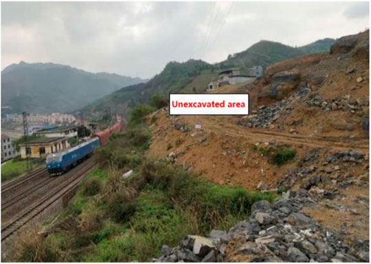
FIGURE 4. Blasting excavation site.
1) The overall construction scheme
From the perspective of safety, efficiency, and low cost, according to the geological terrain and surrounding environmental conditions of the project, and combined with the practical experience of previous similar projects, determined the overall design principles of the project as follows:
1) The reserved rock wall precise micro-vibration control blasting technology is adopted as a whole. Deep hole blasting is used for excavation at a distance from the existing railway (Wang et al., 2010; Gao et al., 2016). The step height is 10 m. Based on the existing terrain and initiation sequence, the free surface direction of the main explosion area is set parallel to the existing railway direction, and the free surface direction of rock wall demolition blasting is set to be away from the existing cable. Schematic diagram of the main blasting scheme of the reserved rock wall is shown in Figure 5, and schematic diagram of excavation section is shown in Figure 6.
2) Diction dike demolition use shallow hole blasting and mechanical crushing combination of weak down, step-by-step away from existing side by shallow hole blasting way by row by hole blasting, resistance line 0.8 ∼ 1.2 m, when residual unexploded rock wall rock to achieve dynamic around critical width, unexploded rock mass reach the state of the “broken and not loose” on the part of the rock mass with the method of mechanical removal, Figure 7 shows the main stone blasting of the reserved dike.
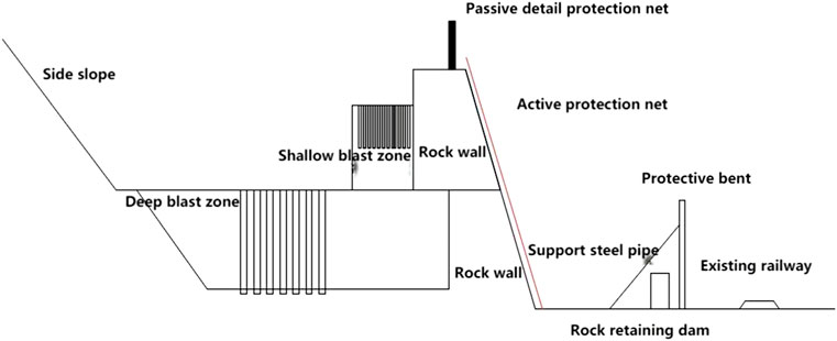
FIGURE 5. Schematic diagram of main blasting scheme for reserved rock wall.
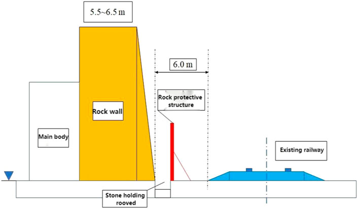
FIGURE 6. Excavation profile diagram.

FIGURE 7. Main rock blasting of reserved rock wall.
In order to conduct a reasonable and accurate blasting test study on rock wall demolition, open terrain rock wall was selected. Before blasting, the width, length, and height of the rock wall were 5.5, 27.3, and 4.6 m, respectively, and the specific parameters are shown in Figure 8.
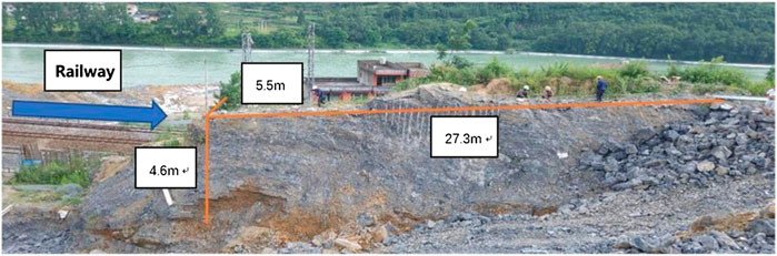
FIGURE 8. Rock wall site for demolition blasting test.
In order to accurately determine the value of the critical width of dynamic self-stability of the rock wall, the selection and cause analysis of the detonation mode of the three blasting of rock wall are as follows:
1) The first blasting adopts millisecond initiation. On the one hand, this method can play a good role in blasting synergy and provide a good critical surface for the subsequent two blasts. On the other hand, when MS1 and MS3 detonators are arranged at intervals, the phenomenon of mutual dryness of stress waves is more obvious, and the stress on the rocks will be greatly reduced in the mutual dryness area, and then large rocks will appear, so as to control flying and rolling rocks.
2) The second and third rock wall blastings are divided into upper and lower steps. The upper step adopts hole-by-hole initiation, and the lower step adopts millisecond initiation. For one thing, the hole-by-hole initiation method can greatly reduce the blasting vibration and control the influence of flying stones on the existing line. For another, the considerable millisecond reduces the stress wave of adjacent blast holes, reduces the blasting synergy to the greatest extent, and makes the upper step loose.
The damage and crack cracking state of the remaining unexploded rock mass were determined by the RSM-SY5 (T) nonmetallic acoustic detector and camera at each blasting. It is confirmed that the unexploded rock mass has reached the state of “broken but not scattered” after three blasts. Schematic diagram of the layout of blasting holes and blasting network for three blasts is shown in Figure 9, in which the first step is the upper bench, and the second and third steps are the lower bench. Blasting parameters are shown in Table 1. Among them, MS1, MS3, MS5, MS7, and MS13 in Figure 9 represent delay 0, 50, 110, 200, and 650 milliseconds, respectively.
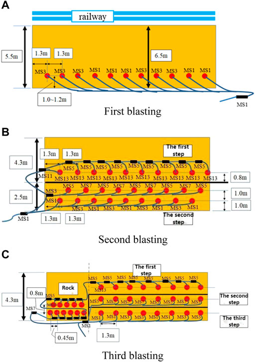
FIGURE 9. Layout and igniting network of three blasting holes.
TABLE 1. Blasting parameters for triple blasting tests.
Fifteen network displacement monitoring points are arranged on the side of the reserved rock wall close to the existing railway (in Figure 10). The 15 monitoring points are located in the west of the rock wall as a whole, and the horizontal and vertical distance between each measuring point is about 1 m. Leica TSP1200 total station and its supporting facilities (in Figure 11) were used to collect the coordinate data of 15 particles before and after blasting. These coordinate data were statistically analyzed, and the displacement differences of 15 particles on the rock wall before and after blasting were plotted as shown in Figure 12. The total displacement differences represent the cumulative displacement differences of three blasting. In the figure, x direction is the side of the vertical rock wall pointing to the railway side, Y direction is parallel to the side of the rock wall pointing to the right face, and Z direction is vertically upward.
FIGURE 10. Site layout and detail arrangement of 15 monitoring points.

FIGURE 11. Field measurement using a total station instrument.
FIGURE 12. Particle displacement difference of rock wall after three blastings. By analyzing the coordinate data of 15 particles on the back of the rock wall, the following conclusions can be drawn.
1) Under the action of explosion shock wave and explosion stress wave, the rock mass enters the dynamic damage stage, and the cracks in the rock mass are activated and spread, which is the fundamental cause of the displacement of particles on the side of the rock wall.
2) Locally, the interpore displacement of each particle is disorganized, the law is not obvious, and the difference is relatively large, which reflects the anisotropy of cracks and joints in the rock mass and the anisotropy of damage in the rock mass.
3) The phenomenon of iron flakes falling off in the blasting process at some particles indicates that the blasting vibration speed at this particle is high and the rock mass produces stripping damage.
4) Test results show that the particle displacement in y direction is larger than that in x direction, and the particle displacement in the z direction is the smallest, this is because an explosive source is too short, which is only 3.756–8.63 m, cylindrical charge after blasting, detonation wave travels along the y direction in wall rock at first side (free surface) of the particle, after refraction, reflection, and transmission in the free surface, the detonation wave propagation velocity in the y direction is the fastest, In addition, the subsequent detonation wave is superimposed with the refracted and reflected detonation wave, resulting in the maximum particle displacement in the y direction. In addition, only y direction is a two-way surface, x and z directions are one-way surface, from the principle of the surface, also particle displacement in Y direction is the largest. Similarly, it can explain the minimum particle displacement in the z direction. When the detonation wave propagates along the z direction, it reaches the roadbed rock mass and then spreads to the railway line foundation. The energy generated by the detonation wave dissipates in the foundation, and the superposition effect on the particles on the side of the rock wall is weakened, so the displacement in the z direction is the minimum.
5) It can be seen from Figure 12 that the displacement variation trend in the three directions is consistent on the whole, that is, the particle displacement in the x, y, and z directions increases or decreases synchronously. When the particle displacement is large, it can be considered that the damage degree of rock mass is high. It can be seen from Figure 12, 1) that, except for some measuring points, the remaining measuring points are all positive, indicating that after the first blasting, the rock wall moves in the positive direction of the coordinate system on the whole, that is, the rock wall moves to the right face, railway side, and upper face on the whole. It can be seen from Figure 12, 2) that most of the measuring points are negative, indicating that after the second blasting, the rock wall moves in the negative direction of the coordinate system as a whole, that is, the rock wall moves to the left of the rock mass, away from the railway line, and vertically downward (in the direction of foundation), which is exactly opposite to the particle displacement movement after the first blasting. As can be seen from Figure 12, 3), the displacement value in the x direction is negative, and the displacement values in the y and z directions are positive, indicating that after the third blasting, the rock wall as a whole moves to the left rock mass, railway side, and upper open face.
6) According to the particle displacement data after the three blastings, the particle displacement of the third time is the largest, the second time is the second largest, and the first time is the smallest. This is because with the increase of blasting times, the distance between blasting sources becomes smaller and smaller, and the cumulative blasting damage increases, which is reflected in the increase of particle displacement on the side of the rock wall. The third mass displacement was the largest, up to 50 mm, and there were iron pieces falling off at multiple masses, which had the most serious damage. 2) Analysis of monitoring results of reserved dike
will be captured by high-speed camera installed in can clear rock wall near the existing side safety area, using high-speed cameras to the reserved rock wall in the process of blasting; blasting rock wall under the action of movement record three times, if the reserved rock wall can appear crack damage phenomenon, such as timely embedding crack observation device, and cracks in the camera system can record the crack initiation process. The third rock wall blasting site is shown in Figure 13.
FIGURE 13. Site map of the third rock wall blasting.
It can be seen from the video of the direction of the blasting face of the rock wall: the first blasting effect is good. Due to the use of micro-difference initiation, almost all the rocks are thrown to the blasting face, and the rock breaking area extends 0.7 m inward from the hole of the gun. From the photos taken at the top, there are some flying stones thrown at the top of the rock wall, but no flying stones thrown at the side of the railway line, only some soil was scattered on the top of the rock wall against the railway line. There are no visible cracks or cracks on the surface of the rock mass in the reserved layer, and the integrity of the rock wall is good. The second blast, as can be seen from the video of the direction of the rock wall blasting proximity surface, the entire blast can be clearly visible into the lower bench micro-differential detonation and the upper bench hole-by-hole detonation. All the rocks of the lower bench were thrown out to the hollow surface, and the rocks were larger; the rocks of the upper bench were not all thrown out, and the rock breaking area was from the shell hole to the hollow surface, which did not extend to the interior of the rock wall, which belonged to loose blasting. From the video on the back of the rock wall, at the upper rock, large cracks have penetrated to airport surface, the part has been out of the rock wall rock blasting, abnormal fluctuation significantly, up to a few centimeters, crackle, top rock wall, partly on the metope with crushed stone fell off, but the rock wall integrity is good, does not produce larger gravel and transverse crack at the top of the distance of 2.5 m, roughly equal to the length of the hole. In the third blasting, it can be seen from the video of the blasting face direction of the rock wall that the rock is not thrown out. The rock breaking area is the rock from the hole to the face of the rock wall, which does not extend to the inside of the rock wall. It is also a loose blasting. From the rock wall on the back of the video to see, at the upper rock (top of the rock distance 2.5 m) is broken, there were dropped chunk, and clear to the rail lateral movement to the rock, rock fall, almost the whole rock can be clear internal joint and fissure, slip on the top of the rock wall surface and have small gravel, and have more than one iron loss, The damage is extremely serious. From the point of view of the whole rock wall, the cracks are mainly concentrated at 2.5 m away from the top (the hole depth is 2.5 m), indicating that within the hole depth, the rock is almost broken and the damage degree is large, and the rock cannot bear another blasting impact. But the rock below the hole, no large rock slide, and damage degree is relatively low.
Before blasting, precise measurement was carried out on the whole dike, and the width of the whole reserved dike was 5.5 m. After blasting and removing the stones, the width of the reserved dike was measured, as shown in Figure 14. As can be seen from the figure, the remaining width after the first blasting test is 3.6 m, the remaining width after the second blasting test is 2.8 m, and the width of the rock wall after the last blasting test is 2.0 m. Through field test again and again by hole blasting test successive approximation are single railway rock wall on the side, after three times of blasting, from the high-speed camera shooting process and failure of rock mass damage degree, the rock mass has been reached “broken and do not come loose blasting effect,” must not again take place to any degree of blasting, at this point since dynamic instability critical width is about 2 m, 2.5 times of resistance line (minimum resistance line is 0.8 m). Therefore, through three on-site blasting tests, it can be concluded that the critical damage width of rock wall demolition blasting is about 2.5 W under the charge of 0.23 kg/m³ and the method of hole-by-hole initiation (MS5 is adopted for the time of slight difference).
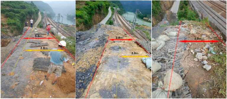
FIGURE 14. Distance between free face and back of rock wall after each blasting.
In this article, the critical damage width of parallel double-free surface blasting is studied and analyzed by combining theoretical analysis and the field test. The conclusions are as follows:
1) Multi-boundary blasting charge calculation formula Q = aKW3, which can quantitatively describe the inner relationship among the throwing effect, boundary conditions, and charge of the throwing blasting; The equivalent sub-charge package model was established, and the relationship between the resistance lines of the double-free surfaces was deduced as
2) Through three on-site blasting tests, we obtained the critical damage width of wall demolition blasting to be about 2.5W under the charge of 0.23 kg/m³, and the method of hole-by-hole initiation is adopted (MS5 is adopted for the time of slight difference).
3) The values of the critical width of instability obtained from theoretical analysis and field experiments are not the same, and generally range from 2w–3w. On the one hand, different rock types and geological conditions give different experimental results, which make them deviate from the theoretical values. On the other hand, the explosive package property indices a1, a2 are obtained based on empirical values, which makes the theoretical values not uniquely determined. In addition, whether the field topography and rock type, the minimum resistance line, and the choice of blast vibration particles have any effect on the results in the field tests need to be further investigated.
The original contributions presented in the study are included in the article/Supplementary Material; further inquiries can be directed to the corresponding author.
All authors listed have made a substantial, direct, and intellectual contribution to the work and approved it for publication.
HM was employed by China Railway Research Institute Group Co., Ltd.
The remaining authors declare that the research was conducted in the absence of any commercial or financial relationships that could be construed as a potential conflict of interest.
All claims expressed in this article are solely those of the authors and do not necessarily represent those of their affiliated organizations, or those of the publisher, the editors, and the reviewers. Any product that may be evaluated in this article, or claim that may be made by its manufacturer, is not guaranteed or endorsed by the publisher.
Di Xinning, , and Yuan, Ye. (2001). Discussion about Directional Throwing Blasting in Multiaspect Facing Empty [J]. Copp. Eng. 4, 14. doi:10.3969/j.issn.1009-3842.2001.04.004
Gao, G., Wang, Z., Song, Z., Shugang, N. A., and Jiang, Y. (2016). Practice of Blasting Technology in High Slope Rock Wall Excavation under Complex Conditions [J]. Water Conservancy Sci. Technol. (24), 231.
Gao, W., and Liu, Y. (2007). Blasting Theory of High and Steep Road Cutting Rock Slope With Multilateral Boundary and its Application [J].. Chinese. J. Rock Mech. Eng. S1, 3397. doi:10.3321/j.issn:1000-6915.2007.z1.122
Gao, W., Xu, S., Liu, M., Wan, J-W., Deng, L., et al. (2010). Reseach on Principle of Charge Amount Calculation in Multilateral Boundary Rock and its Practice. Beijing: Blasting. doi:10.3963/j.issn.1001-487X.2010.03.002
Guo, Y., and xue, li. (2015). Research on Reserved Rock Wall Precision Deep-Hole Controlled Blasting Technology [J]. Shanxi Archit. 16 (06), 65
Huang, C. (2006). Technology of Controlled Blasting Excavation in Railway Cutting under Complex Environment [J]. China Min. ind. 07, 71–73. doi:10.3969/j.issn.1006-7051.2010.02.008
Liu, D. (1999). Practical Manual of Engineering blasting[M]. Beijing: China Metallurgical Industry Press
Liu, Y., and Gao, W. (2006). Modern Road Blasting engineering[M]. Beijing: China Communications Press
Meng, H. (2015). Demolition Technology of Rock Wall by Controlled Blasting with Large Aperture, Wide Hole Spacing and Shallow Hole [J]. Railw. Constr. 07, 86. doi:10.3969/j.issn.1003-1995.2015.07.24
Meng, H., Guo, Y., and Shi, J. (2012). The Technology of Cutting Expansion and Controlled Blasting of Yuzhou-Fuzhou Railway Close to the Existing Line. Guangzhou, China,F: The 10th National Engineering Blasting Academic Conference
Miao, X. (2020). Damage Effect and Damage Mechanism of Rock Mass in Rock-Wall Controlled Blasting [D]. Beijing, China: University of Science and Technology Beijing.
Tang, H., Yi, S., and Lin, D. (2019). Research on Safety Technology of Railway Cutting Blasting Excavation in Complex Environment [J]. Eng. Blasting 25 (01), 24. doi:10.3969/j.issn.1006-7051.2019.01.005
Wang, H. (1992). Dimensional Analysis of Calculation Formula of Multi-Boundary Charge [J], J. Beijing Univ. Technol., 01, 45
Wang, H. (1994). Multi-boundary Stone Blasting Engineering [M]. Beijing: People's Communications Press.
Wang, S., Jin, J., and Li, M. (2008). Rock Blasting Technology in Complex Environment of Xindu Mountain Field Level Project [J]. Eng. blasting 02, 42. doi:10.3969/j.issn.1006-7051.2008.02.010
Wang, Z., Song, Z., Na, S., and Jiang, Y. (2010). Application of Blasting Technology in High Slope Rock Wall Excavation Under Complex Conditions [J]. Engineering Blasting 2, 31–34. doi:10.3969/j.issn.1006-7051.2010.02.008
Keywords: rock blasting, critical damage, free surface, blasting excavation, rock wall collapse
Citation: Shi J, Miao X, Meng H, An H and Zhang W (2022) Study on Critical Damage Width of Parallel Double-Free Surface Blasting. Front. Earth Sci. 10:884558. doi: 10.3389/feart.2022.884558
Received: 26 February 2022; Accepted: 02 June 2022;
Published: 07 July 2022.
Edited by:
Bo Li, Tongji University, ChinaReviewed by:
Liansheng Liu, Jiangxi University of Science and Technology, ChinaCopyright © 2022 Shi, Miao, Meng, An and Zhang. This is an open-access article distributed under the terms of the Creative Commons Attribution License (CC BY). The use, distribution or reproduction in other forums is permitted, provided the original author(s) and the copyright owner(s) are credited and that the original publication in this journal is cited, in accordance with accepted academic practice. No use, distribution or reproduction is permitted which does not comply with these terms.
*Correspondence: Huaming An, aHVhbWluZy5hbkBrdXN0LmVkdS5jbg==
Disclaimer: All claims expressed in this article are solely those of the authors and do not necessarily represent those of their affiliated organizations, or those of the publisher, the editors and the reviewers. Any product that may be evaluated in this article or claim that may be made by its manufacturer is not guaranteed or endorsed by the publisher.
Research integrity at Frontiers
Learn more about the work of our research integrity team to safeguard the quality of each article we publish.