 Chaochao Wang
 Jialin Xu1,2*
95% of researchers rate our articles as excellent or good
Learn more about the work of our research integrity team to safeguard the quality of each article we publish.
Find out more
ORIGINAL RESEARCH article
Front. Earth Sci. , 19 January 2023
Sec. Environmental Informatics and Remote Sensing
Volume 10 - 2022 | https://doi.org/10.3389/feart.2022.1101371
This article is part of the Research Topic Groundwater-Induced Geological Disasters in Underground Engineering: Theoretical, Experimental, and Numerical Approaches View all 12 articles
Isolated overburden grout injection (IOGI) is a green mining method to control surface subsidence. Slurry water significantly influences grouting effectiveness and mining safety. This study establishes a three-dimensional visualization experimental system for slurry “diffusion-bleeding-seepage” to investigate the seepage law of slurry water. The system is composed primarily of a transparent box (1.2 m × 0.5 m × 0.25 m) and support, with the solid–liquid coupling seepage similar material and modules for mining, grouting injection, slurry pressure and displacement monitoring, overburden saturation monitoring, and water leakage monitoring of the working face. A similar material with good permeability and non-disintegration is obtained by hydrophilic, water absorption, and permeability tests. Grouting and mining are simulated by pulling acrylic sheets and pumping slurry. With the fly ash slurry entering the injection layer, the slurry undergoes water–cement separation, and the water bleeding is formed to seep into the similar material. The volumetric water content of the similar material is obtained by arranging multiple groups of volumetric water content sensors into the similar material. The corresponding saturation is obtained by theoretical calculation. The experimental system is used to simulate the seepage of slurry water in a high initial saturation overburden, and the characteristics of injection slurry diffusion and water bleeding are obtained. The profile distribution of seepage of slurry water is found to possess a semi-elliptical shape. Under the condition of high initial saturation, slurry water appears in the working face. The system provides a convenient method for further research of IOGI slurry water seepage.
The isolated overburden grout injection (IOGI) is a key technology for surface subsidence control (Xuan et al., 2014; Xuan and Xu, 2014; Xu et al., 2015a; Xu et al., 2015b). Under the action of pumping pressure, slurry mixed with fly ash (Horiuchi et al., 2000) and water is transported to the mining-induced fracture below the key stratum (Xu et al., 2019; Wang et al., 2022) along the grouting borehole connecting the surface and fracture. Subsequently, the slurry diffuses along the mining-induced space, and water-cement separation occurs. Portions of the slurry water is bleeding, whereas some consolidate to form a wet compacted injection body (Xuan et al., 2016) which supports the overlying strata to reduce its subsidence and control the surface subsidence.
The amount of water contained in the slurry is large; the specific amount of water is closely related to the mining length of the working face, typically at 100,000 m3 or more. The amount of bleed water accounts for approximately half of the total volume (Zhang et al., 2017). This is because the injection layer is close to the working face, and collapse and hydraulic fracture zones exist between them. After a large amount of water bleeds from the slurry, it goes through the pore space of the underlying rock. The seepage of bled water in the underlying rock and its leakage into the working face are key issues that gained substantial attention. However, studies have focused primarily on the effectiveness of grout injection (Xuan et al., 2015), injection ratio control (Xuan et al., 2016) and rock reinforcement in mining engineering (Chen et al., 2022; Chen et al., 2023).
IOGI is affected by different geological and mining conditions. Therefore, studying seepage through mathematical and mechanical methods is challenging. Owing to the “dark box” characteristic of the stratum, field test research also has limitations. Therefore, numerical simulation is a more suitable method to study seepage problem presently, the literature contains numerous seepage simulation studies. For example, COMSOL software was used to study water inrush in fault zones (Yu et al., 2020; Yu et al., 2021; Wu et al., 2022), and the seepage and stability of embankment dams (Tulus and Marpaung, 2018; Wang and Yu, 2021; Zhang et al., 2021). The SEEP/W software was used to study seepage in the landfill leachate layers (Gang et al., 2020), and the smoothed particle hydrodynamics method is efficient and capable of seepage analysis, particularly for the problems with complex geometries (Fadaei-Kermani et al., 2019). Moreover, the UDEC software was used to simulate mining stress of coal seams (Xuan et al., 2014; Fadaei-Kermani et al., 2019), and the FLAC3D was widely used in the study of seepage problems, such as saturated and unsaturated seepage (Li et al., 2012), mined rock seepage (Ma et al., 2006), and slope seepage (Zhang et al., 2020; Zhang et al., 2022). Research on the slurry water bleeding and seepage problem of IOGI involves mining, grouting, slurry flow, and other factors, which renders complexity to analysis. The above numerical methods have limitations in simulating the slurry water seepage problem of IOGI. Physical simulation experiments have high reliability, strong intuitiveness, and good repeatability (Yang et al., 2018). Thus, physical simulation is expected to be an effective way of solving the slurry bled water seepage of IOGI.
Similar simulation materials are necessary for the physical simulation of seepage (Sun et al., 2019). Traditional similar simulation materials are used in physical similarity experiments. However, these materials disintegrate easily when they come in contact with water (Wen et al., 2021). The new fluid-solid coupling similar simulation materials can meet solid deformation and penetration at low strength, with sand as aggregate; additionally, it can be adjusted by paraffin and talcum (Li et al., 2010). High water resistance materials with sand, paraffin, calcium carbonate, petroleum jelly, and gypsum as raw materials have been used to simulate the waterproof layer (Lian et al., 2015). They are used as water-proof materials with low water permeability to simulate the slurry diffusion law at the non-pressure stage (Li J et al., 2020) and the longwall overburden isolated grout injection (Xuan et al., 2020). Polyvinyl alcohol (PVA) is added with river sand, paraffin wax, talcum powder, hydraulic oil, and straw to adjust the permeability. Which does not disintegrate with water and has a specific water storage and permeability capacity (Zheng et al., 2022). Mountain sand, laterite, cement, and water are used as raw materials for different low- and medium-strength fractured rock masses (Guo et al., 2022). Sand and barite powder are used as aggregates; polyurethane and white silicate cement as binders; and water and silicone oil as conditioners to simulate similar materials for rocks of different permeabilities and strengths (Li Z et al., 2020). The material with river sand and clay as aggregate and engine oil and low temperature grease as binder is suitable for coal excavation and seepage (Yang and Zhang, 2020).
In recent years, numerous studies on 3D physical simulation, including simulation of asymmetric destabilization of mine-void rock masses (Lai et al., 2016), large-scale physical simulation experimental system of coal and gas co-mining (Li et al., 2019), and large-scale 3D physical simulation experimental platform of rock strata movement (Zhu et al., 2020; Yang et al., 2021) have been conducted. However, none of these studies involved grouting. For the physical simulation of IOGI, the subsidence problem of grouting injection was studied by injecting water into water bags arranged in similar materials in the early stage (Xuan et al., 2016; Xuan and Xu, 2017). Although grouting could be realized, the slurry water bleeding and seepage of grouting injection could not be realized. With technological improvements, a visual experimental system that can simulate the flow of IOGI was established (Li J et al., 2020; Xuan et al., 2020). Although this system can more adequately respond to the actual slurry diffusion, slurry diffusion studies were performed under the condition of predefined regular injection space. Moreover, none of these studies involved seepage. Locating water in the overburden for visualization and to determine the relationship between the mining layer and water is essential to the experimental system for the seepage of slurry bled water. Fan et al., 2016 applied a fluorescent leak detection agent and experimental ultraviolet lamp to the physical simulation system and developed a new visualized simulation system for solid-liquid two-phase migration in mining-induced overburden. However, it is a two-dimensional system, and thus, the method is unsuitable for three-dimensional models. Based on the current research status, the experimental system cannot fully meet the requirements of monitoring the seepage of slurry bled water and water leakage to the working face.
In this study, a three-dimensional visual and physical simulation experiment system of “diffusion-bleeding-seepage” of IOGI was developed to study the seepage problem of IOGI slurry bled water. The system can simulate coal mining, grouting, slurry diffusion, the slurry bleeding and seepage, the water leakage to working face, and other problems.
IOGI involves working face mining, grouting injection, slurry diffusion, slurry water bleeding, bled water seepage, and rock strata movement. The experimental system used in this study (Figure 1A) adopted a modular design. The similarity ratio between (Figure 1B) and actual slurry injection working conditions was 1:400. The system was composed primarily of a transparent box and support, with the solid–liquid coupling seepage similar material and modules for mining, grouting injection, slurry pressure monitoring, the injection body thickness monitoring, overburden saturation monitoring, and water leakage monitoring of the working face. The box is made of high-strength acrylic plates with a thickness of 2 cm, which are spliced together by means of high-strength special glue.
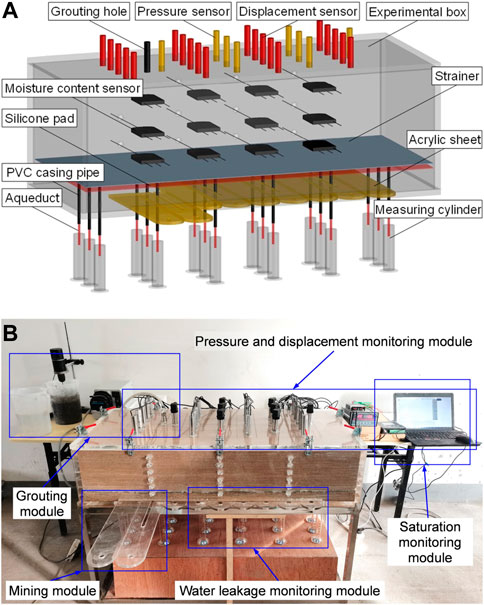
FIGURE 1. Three-dimensional visualization experimental system of “diffusion-bleeding-seepage” for overburden isolated grout injection. (A) Design diagram, (B) physical setup.
The coal seam mining process and the characteristics of its mining space were considered to effectively realize the mining function of the experimental system. Coal seam mining is a process of mining fixed-size rectangular coal blocks along the inclination direction and along the strike direction cyclically and accumulatively. The three-dimensional mining space presents small rectangular spaces formed per unit time and a large rectangular space composed of small rectangular spaces formed cyclically and accumulatively. Therefore, based on this characteristic, several equal volume acrylic sheets were selected as the mining layer. The sheets were placed inside the system, and the bottom end of the front side plate of the experimental box was slotted to meet the requirements of acrylic sheets pulling. The coal seam mining conditions were simulated by pulling the acrylic sheets.
Acrylic sheets with thickness of 1 cm and width of 10 cm were used for mining unit of the mining module. Each piece of acrylic sheet was pulled out to simulate 40 m of coal seam mining along the strike direction. The length of coal seam mining along the inclination and strike directions can be controlled by the number and length of acrylic sheets pulled, respectively. The strike boundary pillar of the model was 15 cm, the inclination boundary pillar was 7.5 cm, acrylic sheet pulling spaces in the system is 90 cm × 35 cm × 1 cm (length × width × height, respectively), and the actual mining range of the simulated coal seam was 360 m × 140 m × 4 m (length × width × height, respectively).
The grouting module consists of a slurry pump, a slurry mixer, slurry storage tank, grouting pipe, grouting hole, and pipe hole connector (Figures 2A–F). The experimental system did not consider the overlying rock of the injection layer considering the visualization of slurry diffusion and the ease of sensor placement. The injection layer was located at the interface between the top plate of the system and the top of the simulated similar material.
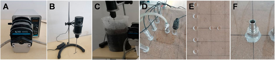
FIGURE 2. Grouting module. (A) Slurry pump, (B) slurry mixer, (C) slurry storage tank, (D) grouting pipe, (E) grouting hole, and (F) pipe hole connector.
During the construction of the simulation system, the grouting pipe connector was inserted into the prefabricated grouting hole location of the top plate and the interface was sealed with hot melt adhesive. Subsequently, one end of the grouting pipe was inserted into the prepared slurry in the slurry storage tank. The other end was drawn out from the slurry in the slurry storage tank and is connected with the slurry pump and pipe hole connector on the top plate of the model. The slurry pump was a constant rate peristaltic metering pump with a pump volume range of 0–380 ml/min.
The similar simulation material should meet the requirements of slurry water seepage while possessing good permeability and not disintegrate water. Therefore, river sand, talcum powder, and solid paraffin were selected as raw materials. The river sand and talcum powder were used as aggregate, and paraffin was used as the cementing material. Different similar material proportioning schemes were tested. Considering the length of the article, this study considered only four similar material proportioning schemes (Table 1), focusing on the non-hydrophilic property, water absorption, and permeability of the similar materials in different proportions.
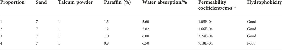
TABLE 1. Hydraulic properties of specimens with different ratios of similar materials.
The material specimens were obtained, as shown in Figure 3, and tested for hydrology. The specimens were soaked for 2 days. The integrity of the specimens after soaking was observed to determine their non-hydrophilicity. The molds were opened and the specimens were taken out and put into the drying oven to be weighed and marked as the drying mass m1. The specimens with different ratios were put into different hydrostatic pressure barrels according to the program, and the specimens were put into the barrels and taken out after every certain time interval to weigh the specimen mass m2, at which time the water absorption rate of the specimens was (m2-m1)/m1. The measurement results of the variable head permeability coefficient of specimens were calculated based on the expression of the variable head permeability coefficient K, expressed as follows: (Tao et al., 2018):
where a is the sectional area of the variable head pipe (cm2), 2.3 is the change factor of ln and log, L is the height of the sample (cm), t1 and t2 are the start and end times of measuring the height of the water column of the pressure measuring tube (s), respectively. H1 and H2 are the start and end head (cm), respectively.
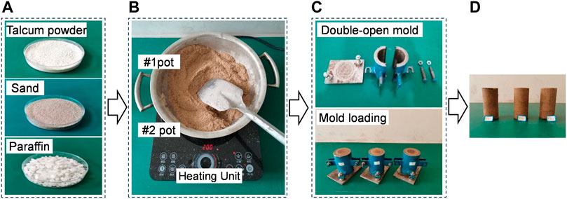
FIGURE 3. Schematic of the production process of similar material specimens. (A) Raw materials, (B) thermostatic heating, (C) test piece forming, and (D) test piece.
Table 1 presents the hydrologic results of different proportions of similar materials. Proportion 3 did not disintegrate with water and had good permeability. Therefore, proportion 3 was used as the solution for this experiment to permeate similar simulated materials. Because the experiment was performed in a pressurized state for approximately 90 min, the water absorption rate of similar materials should be considered for both time and pressure. The results of different hydrostatic pressures for 90 min of the selected proportions of similar materials were tested before the experiment performed to better show the real conditions of the experiment.
According to the test results, the water absorption rate of similar materials at normal temperature conditions under different hydrostatic pressure for 90 min could be expressed as:
The slurry pressures at different locations of the injection layer could be monitored in real time. Pressure sensors were installed on the holes of the top plate of the system. The interface was sealed with hot melt adhesive to monitor the slurry pressure at different locations in the injection layer in real time during the grouting process; the range of the pressure sensor was 0–100 kPa. To study the thickness distribution of the injection body during the grouting process, holes were punched in the top plate of the system and displacement sensors were installed on the hole locations. The displacement sensors were used to monitor the displacement of the bottom interface of the injection body to obtain its thickness. Figure 4 shows the pressure and displacement monitoring data transmission and data acquisition systems.
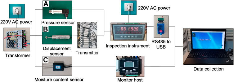
FIGURE 4. System diagram of monitoring data transmission. (A) Pressure, (B) displacement, and (C) saturation.
To study the porosity saturation of overburden during the grouting process, sensors (Figure 4C) were arranged at different locations along the strike direction in the central location of the internal inclination of similar materials. This was performed to realize the dynamic monitoring of the moisture content of the underlying overburden in the horizontal and vertical directions. Not that the output data of the sensor is volumetric water content. The relationship between the actual volumetric water content of the similar materials and that of the sensor were established through experiments to ensure the accuracy of the sensors. The materials used in the sensor calibration experiment were consistent with the similar seepage materials in this study. According to the production process of similar materials, similar cylindrical material specimens with mass moisture contents of 0%, 1.5%, 3%, 4%, 5%, 7%, 10%, 13%, and 15% were made. The dry density of similar materials selected in the calibration experiment was consistent with that of similar materials laid in practice. Figure 5B shows the specific calibration process.
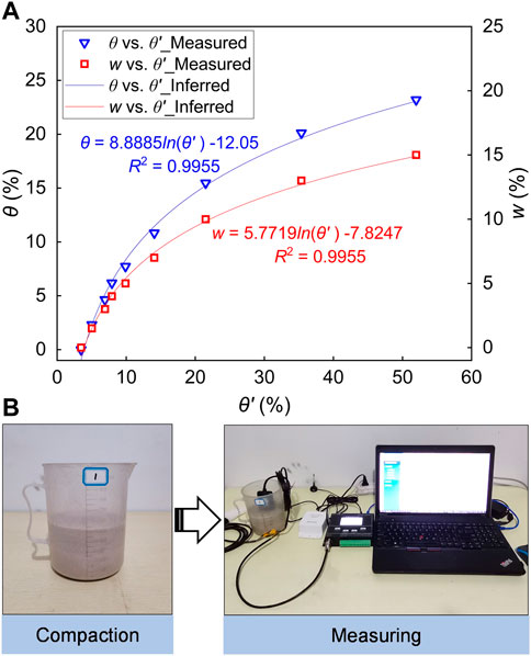
FIGURE 5. (A) Relationship between the value measured by the moisture sensor (θ′) and actual volumetric water content (θ) and mass moisture content (w) of similar materials, and (B) Schematic of the moisture content sensor calibration process.
First, river sand was sieved into particle size of less than 1.7 mm. The sieved river sand was dried using a drying baker such that the initial moisture content of the material was zero. Subsequently, the river sand and talcum powder were weighed according to the material proportion (Table 1, proportion 3), added into the water bath thermostatic heating device to mix, and stirred thoroughly. The required water was added according to the predetermined mass moisture content to ensure that the moisture uniformly distributed.
Second, the material was heated by the water bath thermostatic heating device. When the heating device reached the water bath state, the weighed paraffin was added to the material and stirred repeatedly. The water bath temperature was controlled between 50 and 120°C for the paraffin to melt into the material evenly. Subsequently, the similar material was poured into the prepared measuring cup and compacted. The compaction was performed according to the calculated volume. Finally, the measuring cup was sealed with plastic wrap to prevent moisture evaporation. The experimental material was left to cool for approximately 1 h. Sensor measurement was performed only after the material had cooled down and the paraffin and material were completely mixed and solidified. During the experimental measurement, the sensor probe was inserted into the similar material in the measuring cup to read the measured volumetric water content. Three specimens of each mass moisture content were used for the sensor calibration. Each specimen was measured with #1–12 moisture content sensors.
As shown in Figure 5A, the scatter relationship between the actual volumetric water content (θ) and the volumetric water content (θ′) measured by the sensors could be obtained. The relationship between the actual and measured volumetric water content determined through fitting can be expressed as follows:
According to the relationship between mass moisture content and volume moisture content, The relationship between the actual mass moisture content (w) of similar materials and volumetric water content (θ′) measured by the sensors could be expressed as:
According to the definition of saturation, the relationship between the saturation (S) of the overburden and the volumetric water content (θ′) measured by the sensors is as follows:
where θ is the volumetric water content of similar materials (%), θ′ is the volumetric water content measured by the sensors (%), w is the mass moisture content (%), and S is the saturation (%).
The working face water leakage monitoring module comprised four parts: silicone pad and aqueducts, measuring cylinder, strainer, and PVC casing pipes (Figures 6A–D). To monitor the leakage of slurry bled water in the working face in real time, the rock layer was simplified, and the water flowing fractured and collapse zones (non-seepage layer) were not considered. Bled water was expected to enter the working face through the non-seepage layer. Therefore, the bled water at the upper interface of the non-seepage layer was regarded as the water leakage at the working face.
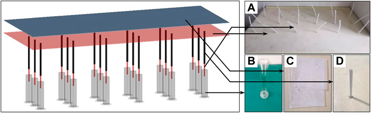
FIGURE 6. Water leakage monitoring module of the working face. (A) Silicone pad and silicone aqueducts, (B) measuring cylinders, (C) strainer, and (D) PVC casing pipes.
Silicone pad were arranged at the interface of the water flowing fractured zone. Subsequently, the silicone aqueducts were connected to the outside of the experimental box by drilling holes in the silicone pad to pass into the measuring cylinders to monitor water leakage to the working surface. Eighteen holes with a diameter of 6 mm were made on the silicone pad, representing 18 measuring points. The aqueducts were connected to the silicone pad using quick-setting adhesive. Since the aqueducts are soft silicone pipes, PVC casing pipes were inserted on the outside of the aqueducts as protective pipes to prevent similar materials moving during mining from compressing the aqueducts so that the water did not flow through the aqueducts. Therefore, PVC casing pipes that are not easily deformed were placed on the outside of the silicone aqueducts. Sealing material was used to prevent bled water from flowing out from the inner wall of the experimental box. A strainer was laid on the upper part of the silicone pad to prevent the similar material on the upper part of the silicone pad from blocking the silicone aqueducts.
Before the experiment, the experimental similar material was made according to the predetermined initial saturation. After the production was completed, the traditional similar material was partially placed to meet the experimental requirements. The monitored saturation was stable, and the initial saturation was obtained as 73%. The layering of similar materials is shown as Table 2. The other modules were assembled to complete the experimental system and ensure good confinement of the experiment. The injection layer was located 25 cm above the coal seam. During the experiment, the acrylic sheet was pumped out 35 cm at an interval of 11 min with a volume of 350 cm3 each time. The total number of acrylic sheets was nine, with a total volume of 3,150 cm3. The sequential relationship between mining and grouting in the modelling is completely based on the field grouting injection condition. Grouting began after the third acrylic sheet was pumped out. The fly ash slurry was made in accordance with the 2:1 water-cement ratio. The grouting flow rate was 75 ml/min. The slurry diffusion was monitored during the grouting process. The grouting was stopped when the working face was mined completely.

TABLE 2. Distribution of experimental lithology.
Under the condition of predefined regular injection space, slurry diffusion with and without pressure were studied. In the non-pressure stage, the slurry exhibited radial and bidirectional diffusion. By contrast, the slurry diffused along the main dominant channel in the pressure stage (Li Z et al., 2020; Li, 2021). The test effectively revealed the basic law of IOGI slurry diffusion. However, no reserved fracture was observed in the actual grouting condition. Figure 10 shows the slurry diffusion at different times under no reserved mining-induced fracture condition (consistent with the actual mining and grouting).
In combination with the grid reference line on the top plate of the experimental system, the distance was measured at different times from the grouting hole to the slurry diffusion boundary (Figure 7). The figure shows that the slurry diffusion was divided into the following two stages. The first stage was the radial fast diffusion stage (Figure 7A), characterized by circular diffusion centered on the grouting hole. Herein, the diffusion radius increased with time and exhibited a power function distribution. The second stage was strike direction diffusion accompanied by radial slow diffusion (Figure 7B) and characterized by elliptical diffusion. As shown in Figure 8, the distance (L1) from the front end of the strike diffusion boundary to the grouting hole increased with time and was distributed as a power function. Moreover, the radial diffusion was accompanied by the radial diffusion during the radial diffusion process. The radial diffusion speed in the second stage was slower than that in the first stage. The distance (L2) from the back end of the strike diffusion boundary to the grouting hole coincided with the radius (r) of the radial diffusion, thus indicating that radial diffusion exists during the strike diffusion process.
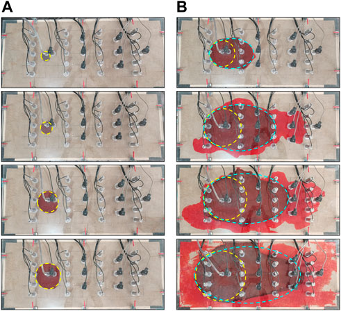
FIGURE 7. Slurry diffusion. (A) Radial fast diffusion (0–2.5 min), (B) strike direction diffusion (2.5–45 min).
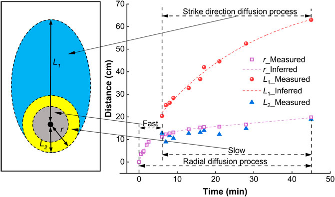
FIGURE 8. Slurry diffusion distance (from the grouting hole to slurry diffusion boundary) vs. time. Here, r indicates the radial diffusion radius, L1 indicates the distance from the front end of the strike diffusion boundary to the grouting hole, and L2 indicates the distance from the front back of the strike diffusion boundary to the grouting hole.
When fly ash slurry diffuses, water-cement separation occurs; the process is known as slurry water bleeding. When the slurry diffused rapidly in the radial direction, the diffusion speed of the slurry was high, and the amount of bled water was small (Figure 9A). When the slurry diffused in the strike direction, the diffusion speed of the slurry was reduced, and the amount of bled water increased. The bled water is distributed primarily in the front end of the slurry in the early stage (Figure 9B) and in the front and both sides of the slurry in the late stage (Figure 9C).
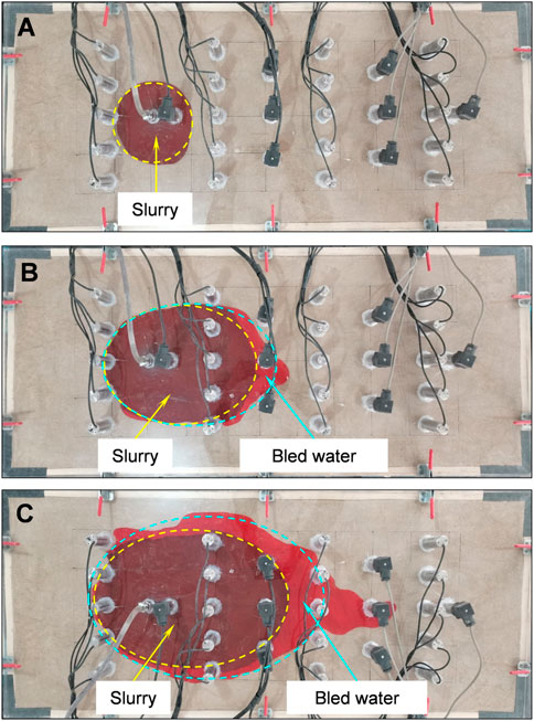
FIGURE 9. Distribution of slurry water bleeding. (A) Radial fast diffusion, (B) strike direction diffusion (early stage), and (C) Strike direction diffusion (later stage).
The saturation curves (Figure 10) of different measurement points in the overburden were obtained, according to the method in Section 2.4. The saturation of the overburden was shown at four stages: before grouting, during grouting, during leakage, and after leakage. Before grouting, the initial saturation (Sr) of the overburden was 73%. This value did not change with time and was uniform in different locations. During grouting, the saturation of the overburden increased from 73% to 100%; this value remained unchanged, thus indicating that the slurry bled water seeped into the overburden from the injection layer, and the saturation finally reached complete saturation (Sf). After grouting, the locations of measuring points #3 and #6 (Figure 11F) did not reach complete saturation, whereas the rest of the points reached full saturation state (Sf). When the water leakage monitoring for 120 min, grouting was stopped immediately. When the bled water entered the working face, the saturation of measuring point locations #1–#3 and #12 did not change significantly, whereas that of other measuring point locations decreased significantly. The saturation decreased faster, and the amount of reduction was larger at the location closer to the water leakage point of the working face. By contrast, the decrease was slow, and the amount of reduction was small at the location farther from the water leakage point of the working face. After water leakage, the saturation of all measuring point locations in the overburden remained unchanged.
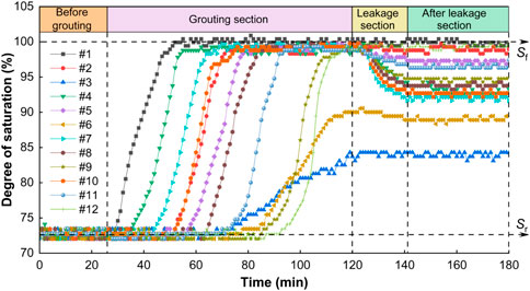
FIGURE 10. Degree of saturation for #1–12 vs. time. Here, Sr indicates initial saturation and Sf indicates complete saturation.
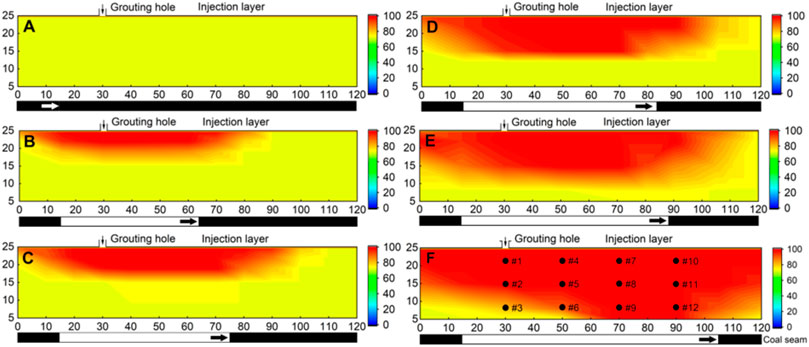
FIGURE 11. Strike profile contour of saturation for α = 0%–55% along the central location of the inclination during grouting. (A) 0%, (B) 15.6%, (C) 25%, (D) 30%, (E) 38%, and (F) 55%. Here, α is the injection ratio.
Based on the saturation monitoring method in Section 2.5, the strike profile contour (Figures 11A—F) of the overburden saturation with different injection ratios (α = 0%–55%) in the grouting process was obtained according to Eq. 5. The profile revealed that the overburden full saturation range increased with an increase in the injection ratio. This indicates that the amount of the bled water increased with an increase in the amount of grouting slurry in the injection layer. Moreover, the bled water continued to seep into the overburden and to a more distant location, thereby increasing the overburden full saturation range. The distribution pattern of the slurry bled water seepage in the overburden was semi-elliptical. Its dynamic distribution pattern was not always centered on the grouting hole instead, but the center of its pattern continued to move in the mining direction as the grouting fracture expanded to the mining direction.
A physical simulation experimental method was used to study the slurry bled water seepage problem of IOGI. Considering the actual IOGI technical conditions and their interrelationship, an experimental simulation method for the slurry bled water seepage of IOGI was established to realize the visualization study of slurry diffusion and water secretion, and locating water in the overburden for visualization and to determine the relationship between the mining layer and water is essential to the experimental system for the seepage of slurry bled water. The experimental method can be used to further develop the water leakage in working face and other related problems.
Based on this experimental system, physical simulation experiments of IOGI under the initial saturation of 73% were performed. The slurry diffusion was divided into two stages: radial fast diffusion and strike direction diffusion accompanied by radial slow diffusion. When the slurry diffused radially and rapidly, the slurry diffused faster, and the amount of bled water was very small. When the slurry diffused in the strike direction, the diffusion speed of the slurry was reduced, and the amount of bled water increased. The bled water was distributed primarily in the front end of the slurry in the early stage and in the front end and both sides of the slurry in the late stage. The relationship between the dynamic change in saturation and grouting condition was obtained. The seepage process of slurry bled water in the overburden and the strike profile contour saturation distribution was obtained; its distribution pattern was semi-elliptical.
The influence of factors, such as grouting volume, grouting pressure, initial saturation, and permeability coefficient, on the seepage law of bled water was not studied. Therefore, the following research focuses on these factors and establishes the seepage boundary model under different mining and geological conditions to build the seepage prediction method of working face to evaluate the risk of slurry water.
The original contributions presented in the study are included in the article/Supplementary Material, further inquiries can be directed to the corresponding authors.
CW contributed to the conception of the study; CW and JL performed the experiment; CW contributed significantly to analysis and manuscript preparation; CW performed the data analyses and wrote the manuscript; JX and DX helped perform the analysis with constructive discussions.
This research was supported by Fundamental Research Funds for Central Universities [2020ZDPYMS15].
The authors declare that the research was conducted in the absence of any commercial or financial relationships that could be construed as a potential conflict of interest.
All claims expressed in this article are solely those of the authors and do not necessarily represent those of their affiliated organizations, or those of the publisher, the editors and the reviewers. Any product that may be evaluated in this article, or claim that may be made by its manufacturer, is not guaranteed or endorsed by the publisher.
Chen, J., Liu, L., Zeng, B., Tao, K., Zhang, C., Zhao, H., et al. (2023). A constitutive model to reveal the anchorage mechanism of fully bonded bolts. Rock Mech. Rock Eng. 56, 3.
Chen, J., Zeng, B., Liu, L., Tao, K., Zhao, H., Zhang, C., et al. (2022). Investigating the anchorage performance of full-grouted anchor bolts with a modified numerical simulation method. Eng. Fail. Anal. 141, 106640–106714. doi:10.1016/j.engfailanal.2022.106640
Fadaei-Kermani, E., Shojaee, S., Memarzadeh, R., and Barani, G. (2019). Numerical simulation of seepage problem in porous media. Appl. Water Sci. 9 (4), 79–88. doi:10.1007/s13201-019-0965-1
Fan, G., Zhang, S., Zhang, D., and Chen, M. (2016). Development and application of a solid-liquid coupling physical experiment system for modeling mining-induced overburden movement. J. Min. Saf. Eng. 33 (5), 898–903. doi:10.13545/j.cnki.jmse.2016.05.021
Gang, L., Li, G., Zhang, J., and Liu, J. (2020). Numerical simulation of seepage in the landfill leachate layers. IOP Conf. Ser. Earth Environ. Sci. 545, 012038. doi:10.1088/1755-1315/545/1/012038
Guo, Y., Yang, Y., Kong, Z., and He, J. (2022). Development of similar materials for liquid-solid coupling and its application in water outburst and mud outburst model test of deep tunnel. Geofluids 2022, 1–12. doi:10.1155/2022/8784398
Horiuchi, S., Kawaguchi, M., and Yasuhara, K. (2000). Effective use of fly ash slurry as fill material. J. Hazard Mater 76 (2), 301–337. doi:10.1016/S0304-3894(00)00205-3
Lai, X., Shan, P., Cao, J., Cui, F., and Sun, H. (2016). Simulation of asymmetric destabilization of mine-void rock masses using a large 3D physical model. Rock Mech. Rock Eng. 49 (2), 487–502. doi:10.1007/s00603-015-0740-z
Li, J. (2021). Experimental study on the flow law of slurry of isolated grouting in mining-induced overburden. China: China University of Mining and Technology.
Li, J., Zheng, K., Xuan, D., and Xu, J. (2020). Experimental study on slurry diffusion law during the non-pressure stage in overburden isolated grouting. J. China Coal Soc. 45, 78–86. doi:10.13225/j.cnki.jccs.2019.1669
Li, S., Feng, X., Li, S., Li, L., and Li, G. (2010). Research and development of a new similar material for solid-fluid coupling and its application. Chin. J. Rock Mech. Eng. 29 (2), 281–288.
Li, S., Wei, Z., Lin, H., Zhao, P., Xiao, P., and Hao, Y. (2019). Research and development of 3D large-scale physical simulation experimental system for coal and gas co-extraction and its application. J. China Coal Soc. 44 (1), 236–245. doi:10.13225/j.cnki.jccs.2018.1635
Li, Y., Wu, J., and Li, K. (2012). Saturated-unsaturated seepage analysis based on FLAC3D. Rock Soil Mech 33 (2), 617–622. doi:10.16285/j.rsm.2012.02.001
Li, Z., Ma, M., and Bao, Y. (2020). Development and application of fluid-solid coupling similar materials in discharge test of old goaf water. Geofluids 2020, 1–12. doi:10.1155/2020/8834885
Lian, H., Xia, X., Ran, W., and Zhao, Q. (2015). Experimental research on water-resistance property of new-style fluid-solid coupling material for analogue simulation. Coal Min. Technol. 20 (1), 12–16. doi:10.13532/j.cnki.cn11-3677/td.2015.01.004
Lu, H., Zhang, K., Yi, J., and Wei, A. (2022). A study on the optimal selection of similar materials for the physical simulation experiment based on rock mineral components. Eng. Fail. Anal. 140, 106607. doi:10.1016/j.engfailanal.2022.106607
Ma, L., Zhang, D., Miao, X., Wang, H., and Feng, J. (2006). Numerical simulation of seepage regularities with FLAC3D in the overlying strata in mining rockmass. J. Hunan Univ. Sci. Technol(Nat Sci. Ed. 21 (3), 1–5.
Sun, W., Zhou, F., Shao, J., Du, H., and Xue, Y. (2019). Development status and prospects of mine physical similar material simulation experiments. Geotech. Geol. Eng. 37 (4), 3025–3036. doi:10.1007/s10706-019-00821-4
Tao, G., Wu, X., Yang, X., Liu, W., He, J., and Chen, Y. (2018). Pore distribution of cement-soil and its effect on permeability. J. Eng. Geol. 26 (5), 1243–1249. doi:10.13544/j.cnki.jeg.2018011
Tulus, S., and Marpaung, T. (2018). Sedimentation optimization on river dam flow by using COMSOL multiphysics. IOP Conf. Ser. Mat. Sci. Eng. 300, 012051. doi:10.1088/1757-899X/300/1/012051
Wang, F., Chen, T., Ma, B., and Chen, D. (2022). Formation mechanism of stress arch during longwall mining based on key strata theory. Energy Explor. Exploitation 40 (2), 816–833. doi:10.1177/01445987211042701
Wang, R., and Yu, K. (2021). Stress and deformation analysis of high concrete face rockfill dam based on COMSOL multiphysics. IOP Conf. Ser. Earth Environ. Sci. 643, 012013. doi:10.1088/1755-1315/643/1/012013
Wen, Z., Jiang, P., Jing, S., Cao, Z., and Guan, Y. (2021). Development and verification of simulation testing system for floor seepage in coal mine underground reservoir. J. China Coal Soc. 46 (5), 1487–1497. doi:10.13225/j.cnki.jccs.st20.1601
Wu, J., Wang, X., Wu, L., Lu, Y., and Han, Y. (2022). Parametric study of water inrush in a tunnel crossing a fault based on the “three zones” fault structure. KSCE J. Civ. Eng. 26 (8), 3600–3619. doi:10.1007/s12205-022-1310-z
Xu, J., Ni, J., Xuan, D., and Wang, X. (2015a). Coal mining technology without village relocation by isolated grout injection into overburden. Coal Sci. Technol. 43 (12), 8–11. doi:10.13199/j.cnki.cst.2015.12.002
Xu, J., Xuan, D., Zhu, W., and Wang, X. (2019). Partial backfilling coal mining technology based on key strata control. J. Min. Strata Contr Eng. 1 (1), 69–76. doi:10.13532/j.jmsce.cn10-1638/td.2019.02.006
Xu, J., Xuan, D., Zhu, W., Wang, X., Wang, B., and Teng, H. (2015b). Study and application of coal mining with partial backfilling. J. China Coal Soc. 40 (6), 1303–1312. doi:10.13225/j.cnki.jccs.2015.3055
Xuan, D., Li, J., Zheng, K., and Xu, J. (2020). Experimental study of slurry flow in mining-induced fractures during longwall overburden grout injection. Geofluids 2020, 1–10. doi:10.1155/2020/8877616
Xuan, D., and Xu, J. (2014). Grout injection into bed separation to control surface subsidence during longwall mining under villages: Case study of liudian coal mine, China. Nat. Hazards 73 (2), 883–906. doi:10.1007/s11069-014-1113-8
Xuan, D., and Xu, J. (2017). Longwall surface subsidence control by technology of isolated overburden grout injection. Int. J. Min. Sci. Technol. 27 (5), 813–818. doi:10.1016/j.ijmst.2017.07.014
Xuan, D., Xu, J., Wang, B., and Teng, H. (2015). Borehole Investigation of the effectiveness of grout injection technology on coal mine subsidence control. Rock Mech. Rock Eng. 48 (6), 2435–2445. doi:10.1007/s00603-015-0710-5
Xuan, D., Xu, J., Wang, B., and Teng, H. (2016). Investigation of fill distribution in post-injected longwall overburden with implications for grout take estimation. Eng. Geol. 206, 71–82. doi:10.1016/j.enggeo.2016.04.007
Xuan, D., Xu, J., and Zhu, W. (2014). Dynamic disaster control under a massive igneous sill by grouting from surface boreholes. Int. J. Rock Mech. Min. Sci. 71, 176–187. doi:10.1016/j.ijrmms.2014.06.019
Yang, K., Liu, W., Jiao, B., Zhang, Q., Liu, S., and ZhangZ, (2021). Three-dimensional physical simulation of overburden migration in deep thick hard roof fully-mechanized caving mining. Chin J Geotechn Eng 43 (1), 85–93. doi:10.11779/CJGE202101010
Yang, R., Zhang, Y., Wang, Z., Wang, Y., Lv, C., Wang, C., et al. (2018). A newly-built geomechanical model test system and its application. J. China Coal Soc. 43 (2), 398–404. doi:10.13225/j.cnki.jccs.2017.1476
Yang, T., and Zhang, J. (2020). Experimental research on simulation material for water-resisting soil layer in mining physical simulation. Adv. Mater. Sci. Eng. 2020, 1–8. doi:10.1155/2020/3456913
Yu, H., Zhu, S., and Wang, X. (2021). Research on groundwater seepage through fault zones in coal mines. Hydrogeol. J. 29, 1647–1656. doi:10.1007/S10040-021-02336-W
Yu, H., Zhu, S., Xie, H., and Hou, J. (2020). Numerical simulation of water inrush in fault zone considering seepage paths. Nat. Hazards 104, 1763–1779. doi:10.1007/s11069-020-04246-8
Zhang, L., Xu, J., and Xuan, D. (2017). Experimental research on slurry bleeding properties grouting filling for overburden. China coal. 43 (9), 121–124. doi:10.19880/j.cnki.ccm.2017.09.025
Zhang, Q., Wang, L., Zhang, H., and Gao, H. (2022). Parameter sensitivity and unsaturatedstochastic seepage field of bench slope. J. Saf. Environ. 22, 665–672. doi:10.13637/j.issn.1009-6094.2020.1625
Zhang, W., Shen, Z., Ren, J., Bian, J., Xu, L., and Chen, G. (2021). Multifield coupling numerical simulation of the seepage and stability of embankment dams on deep overburden layers. Arab. J. Sci. Eng. 47 (6), 7293–7308. doi:10.1007/s13369-021-06112-6
Zhang, Y., Zhang, X., Wang, Z., and Zhu, W. (2020). Study on the reservoir dam slope stability considering the effect of seepage. IOP Conf. Ser. Earth Environ. Sci. 560, 012049. doi:10.1088/1755-1315/560/1/012049
Zheng, K., Xuan, D., and Li, J. (2022). Study on fluid-solid characteristics of grouting filling similar-simulation materials. Minerals 12 (5), 502. doi:10.3390/min12050502
Keywords: isolated overburden grout injection, water bleeding, seepage, physical simulation experiment, saturation
Citation: Wang C, Xu J, Xuan D and Li J (2023) Experimental method and application of the slurry “diffusion-bleeding-seepage” of isolated overburden grout injection. Front. Earth Sci. 10:1101371. doi: 10.3389/feart.2022.1101371
Received: 17 November 2022; Accepted: 24 November 2022;
Published: 19 January 2023.
Edited by:
Danqi Li, Curtin University, AustraliaReviewed by:
Jianhang Chen, China University of Mining and Technology, Beijing, ChinaCopyright © 2023 Wang, Xu, Xuan and Li. This is an open-access article distributed under the terms of the Creative Commons Attribution License (CC BY). The use, distribution or reproduction in other forums is permitted, provided the original author(s) and the copyright owner(s) are credited and that the original publication in this journal is cited, in accordance with accepted academic practice. No use, distribution or reproduction is permitted which does not comply with these terms.
*Correspondence: Jialin Xu, Y3VtdHhqbEBjdW10LmVkdS5jbg==; Dayang Xuan, ZGF5YW5nLnh1YW5AY3VtdC5lZHUuY24=
Disclaimer: All claims expressed in this article are solely those of the authors and do not necessarily represent those of their affiliated organizations, or those of the publisher, the editors and the reviewers. Any product that may be evaluated in this article or claim that may be made by its manufacturer is not guaranteed or endorsed by the publisher.
Research integrity at Frontiers
Learn more about the work of our research integrity team to safeguard the quality of each article we publish.