 Wenbin Cai
 Xiangyang Mo
 Wen Li2
- 1College of Petroleum Engineering, Xi’an Shiyou University, Xi’an, China
- 2Research Institute of Engineering Technology, PetroChina Xinjiang Oilfield Company, Karamay, China
This study performed in-depth analysis of onsite fatigue damage and stress distribution in pumping rods. Two aspects of fatigue damage were analyzed: macroscopic morphology and chemical properties. In terms of chemical properties, the crystalline phase composition and hardness of the product at fatigue damage were analyzed; the stress distribution was analyzed in term so of the rod-body stress and the connection-section stress. The cross-sectional characteristics of the fatigue crack expansion were summarized, and the types of fatigue fracture and the influencing factors of the pumping rod were obtained from these cross-sectional characteristics. Finally, modeling and stress analysis of the pumping rod were performed using SolidWorks and ABAQUS software. By comparing the stress cloud diagrams of different thread root shapes, the factors that cause fracture in the pumping rod and the locations of stress concentrations and dangerous cross-sections of the rod were determined. The highest principal stresses were obtained at the rod body near the upsetting flange of the pumping rod, and fatigue damage was the most likely to occur at this location. The shoulder of the unloading groove and the upsetting flange area were relatively safe because of their large cross-sectional area and less likelihood to produce stress concentrations. The results of this study can provide scientific guidance and reference for the development of pumping rods for efficient oil production and the improvement of oil and gas production efficiency.
1 Introduction
The pumping rod is a crucial link in a pumping system but weaker than ground equipment. A common form of damage to the pumping rod is fracture, wherein the rod is subjected to asymmetric cyclic loading during service; the cracks form and expand until fracture occurs (Gibbs and Neely, 1966). Fractures do not only influence production but also cause large economic losses. According to a field survey, the sum of the well operation cost and discounted production of crude oil was 20–30 thousand yuan per rod breaking accident. In one oil field, there were a total of 821 pumping rod breakage accidents from 1995 to 1998, accounting for 62% of the total number of wells repaired and economic losses of more than 20 million yuan (Chen et al., 1994). Thus, ensuring normal operation of the pumping rod helps improve crude oil production and reduce production costs with significant social and economic benefits.
Several studies have been performed worldwide, and the fatigue life of the pumping rod column was investigated from the perspective of crack expansion (Li et al., 1994a; Zhang et al., 2000; Ding et al., 2019). The German engineer Wöhler experimentally analyzed fatigue phenomena and laid the foundation for fatigue research in a paper on the subject. In the 1950s, researchers began to use techniques such as electron microscopy to investigate cracking, thus inspiring the development of fracture mechanics theory. Ghofrani and Ulmanu (Ulmanu and Ghofrani, 2001) applied the theory of crack expansion and calculated the fatigue life of pumping rods. Li Qi et al. (Li et al., 1994b) analyzed the expressions of the stress intensity factor of rod cracks and the crack extension life based on the theoretical principle of fracture mechanics. Guoli et al. (Wang and Wei, 1994) obtained the fatigue crack expansion rate of the rod and column. Xiaobing et al. (Xu and Yuan, 1993) performed theoretical analysis and experimental simulation to apply fracture mechanics theory to predict the fatigue life of a pumping rod with a crack extension. Xiuhua et al. (Du et al., 2006) used the fracture mechanics theory to investigate the influence of the crack expansion condition of the rod-post surface on the cracking of the rod-post system. Zizi et al. (Xiang et al., 2010) constructed the calculation models for the fatigue crack expansion rate and fatigue limit at threshold stress-intensity factor and fatigue life.
To effectively prevent and reduce oil-well repair to fix pumping rod fracture and further reduce the costs of oil-field development, the present study analyzed fatigue fracture samples of pumping rods from an oil field site and used SolidWorks and ABAQUS software to model and statically analyze pumping rods and rod head thread connections. This study also predicted the locations where stress concentration pumping rods are prone to be concentrated during operation and provided guidance for the selection and application of pumping rods.
2 Analysis of onsite pumping rod fatigue damage
2.1 Macroscopic analysis of fatigue damage of sucker rods
Under complex well conditions, the fatigue life of the pumping rod considerably decreased, and several obvious signs of fatigue fracture were observed in the fracture area. Furthermore, a substantial amount of information related to the fatigue fracture process was retained, with obvious morphological characteristics representative of fatigue fracture (Li, 2006). As displayed in Figure 1, a layer of red-brown oil well corrosion products formed on the fracture surface of the pumping rod, and the fracture crack originated on the outer surface of the pumping rod. The area of the transient fracture zone accounts for about 1/5 of the entire fatigue fracture area, indicating that fracture load level was low in the transient fracture zone of the pumping rod; the fracture was relatively less severe, and no necking phenomenon occurred in the brittle transient fracture. Thus, the fracture occurred because of the alternating load and corrosion media under the combined effect of low stress brittle fracture.
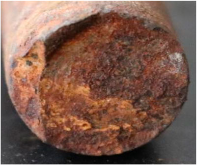
FIGURE 1. Fatigue cross-sectional shape of the pumping rod.
As displayed in Figure 2, the pumping rod was fractured from the rod body (As shown on the left A), are several corroded pits (As shown on the right B) were formed in the rod body. The corrosion caused a reduction in the fracture surface area of the pumping rod and in the load-bearing capacity. The formation of corrosion pits in the pumping rod body at the site of a local stress concentration resulted in fatigue cracks at the bottom of the corrosion pits in the cyclic alternating load and corrosion medium. Therefore, fatigue cracks continued to expand forward until the final fracture occurred, and the cycle corresponding to the low circumference corrosion fatigue fracture was relatively short.
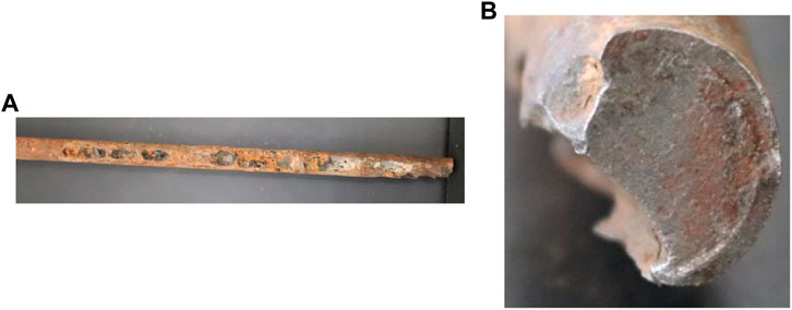
FIGURE 2. Fatigue cross-sectional shape of the pumping rod.
As displayed in Figure 3, the fatigue fracture occurred because of manufacturing defects in the pumping rod. Dark black inclusions were observed inside the rod when it was manufactured. During the upward and downward movement, the pumping rod was subjected to alternating load, resulting in gradual sprouting and expansion of the crack source. The fracture occurred rapidly when the fatigue crack expanded to the inclusions.
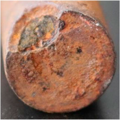
FIGURE 3. Fatigue cross-sectional shape of the pumping rod.
2.2 Pumping rod material performance analysis
Two typical rod specimens were selected for testing the composition and hardness and analyzing the composition of the crystalline phase of the fatigue damage products to determine the factors influencing the fatigue damage of the pumping rods. The two specimens were numbered 1 and 2, as displayed in Figures 4, 5.
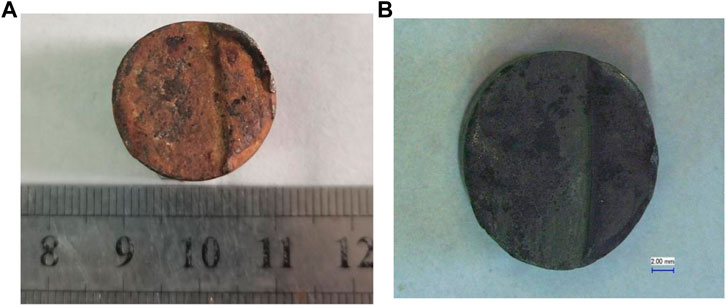
FIGURE 4. Before and after fracture cleaning of specimen No. 1. (A) Before fracture cleaning. (B) After fracture cleaning.
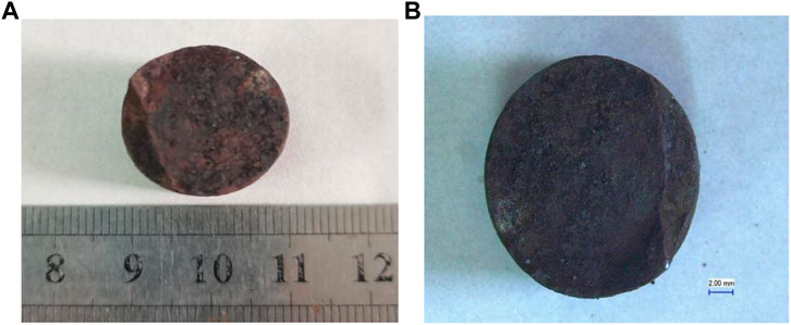
FIGURE 5. Before and after fracture cleaning of specimen No. 2. (A) Before fracture cleaning. (B) After fracture cleaning.
2.2.1 Analysis of the chemical composition of pumping rods
A Q4 TASMAN direct reading spectrometer was used to test the composition of specimen No. 1 and No. 2, and the results are displayed in Table 1.
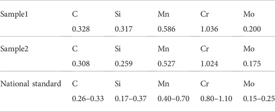
TABLE 1. Chemical composition of specimen.
Comparison of the data in Table 1 indicated that the chemical composition of specimen No.1 and No.2 satisfied the national standard.
2.2.2 Analysis of crystalline phase composition of products at fatigue damage
An X-ray diffractometer XRD-6000 was used to analyze the crystal phase composition at the fatigue fracture of specimen No. 1 and No. 2. The experimental conditions were as follows: filtered Cu, high voltage intensity of 40 kV, current of 30 mA, continuous scanning at 2θ angle 10–90° and rate of 10°/min.
Samples obtained from specimen No. 1 and No. 2 were ground into powder and then analyzed for their physical phases. Figures 6, 7 display the XRD patterns of specimen No. 1 and specimen No. 2.
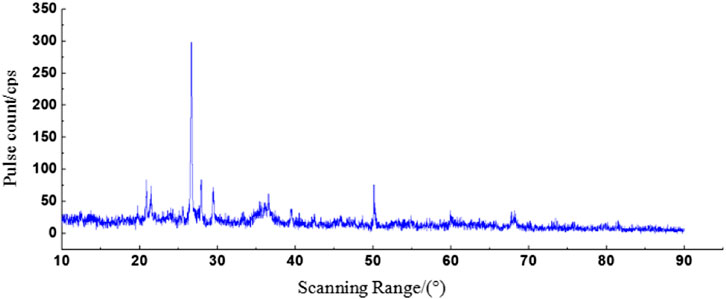
FIGURE 6. XRD pattern of specimen No. 1.
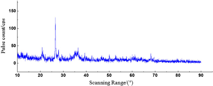
FIGURE 7. XRD pattern of specimen No. 2.
XRD analysis of specimen No. 1 and No. 2 revealed that the primary components of the products formed at the fatigue damage of the pumping rods were FeS compounds, Fe2O3, and silicon compounds. The FeS in the specimens was supposed to be produced by the corrosion of H2S in the well fluid. The production of Fe2O3 is closely related to the CO2 corrosion and HCO3− occurring in the well fluid, and the silicon-like compounds should be substances in the formation.
2.2.3 Hardness test
The specimens were intercepted at two typical pumping rod fractures, and the TH-500 Rockwell hardness tester was used to conduct multi-point hardness tests and obtain average values; the results are displayed in Table 2.
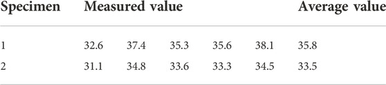
TABLE 2. Hardness test results.
As illustrated in Table 2, the hardness values of specimens No. 1 and No. 2 were 35.8 HRC and 33.5 HRC, respectively. Therefore, the hardness of the pumping rod after fatigue fracture was consistent with the provisions of SY/T5029-2013 Pumping Rod.
3 Analysis of pumping rod stress distribution
3.1 Analysis of rod stress
The simulation model of the pumping rod was constructed using SolidWorks software. The pumping rod column was subjected to cyclic alternating loads during the upward and downward strokes. Because of the complex downhole working environment, the load on the pumping rod column should have been simplified for fatigue life simulation analysis of the pumping rod column; therefore, a simulation model of the pumping rod was established.
The pumping rod model was constructed using SolidWorks modeling software and imported into the finite element analysis software ABAQUS to correct a few dimensional errors that occurred during the import. The pumping rod model was then meshed, and the tetrahedral meshing method was used because of the complex shape of the threads. The meshes at the wrench side, threads, and upsetting flange of the pumping rod were encrypted.
The alternating load consistent with that used in practice was calculated using the production data of an oil well in Shengli Oilfield; its well production data is displayed in Table 3.

TABLE 3. Well production data.
As displayed in Figure 8, the workover diagram of the pumping rod over the length of one stroke was obtained by combining the well production data, the variation in the load of the pumping rod, and the displacement of the suspension point over one stroke (Lin and Smith, 1999). Furthermore, according to the suspension point displacement combined with the motion of the pumping machine, the obtained work graph of the pumping rod was transformed into a curve of load variation with time as displayed in Figure 9.
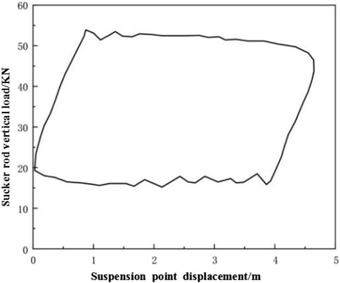
FIGURE 8. Function of the oil well.
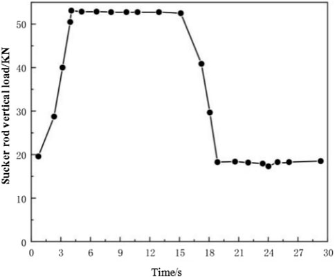
FIGURE 9. Load variation diagram.
The alternating load was applied within one stroke according to the aforementioned calculations, using the amplitude curve in ABAQUS.
As displayed in Figure 10, the cloud map of the maximum principal stress distribution on the pumping rod was obtained through simulation analysis, which revealed that the maximum principal stresses at the root of the threads at both ends of the rod, the root of the shoulder, the wrench side, and near the upsetting flange of the rod were large and hazardous. The shoulder of the unloading groove and the upsetting flange area were relatively safe due to the large cross-sectional area and low stress concentration (Zhao, 2007; Bian et al., 2011). As displayed in Figure 11, the deformation cloud was small along the axis of the pumping rod in the working process, where the maximum deformation was 0.2267 mm.
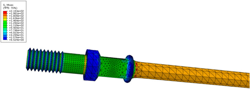
FIGURE 10. Pumping rod equivalent force cloud.
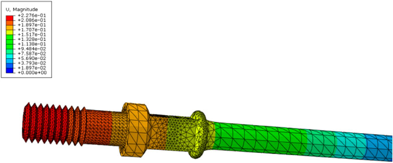
FIGURE 11. Pumping rod deformation cloud.
As illustrated in Figure 12, the principal stress variation curves during strokes at the root of the thread, the root of the shoulder, the wrench side, and the rod body near the upsetting flange in the pumping rod were plotted according to the results of static analysis using ABAQUS. The maximum principal stress occurred during the upward stroke and the minimum principal stress occurred during the downward stroke of the pumping rod. Thus, the maximum principal stress was observed near the upsetting flange of the rod body, and the possibility of fatigue damage was the highest at this location of the rod, making it a hazardous section.
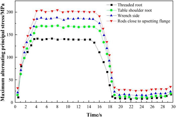
FIGURE 12. Stress variation curves at different locations within one stroke of the pumping rod.
3.2 Stress analysis of pumping rod connection section
The geometric model of the pumping rod coupling was constructed using SolidWorks modeling software and imported into ABAQUS software. The coupling was assembled with the pumping rod in the assembly environment, as displayed in Figure 13.
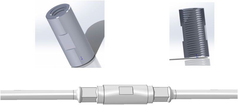
FIGURE 13. Connection diagram of joint and pumping rod.
To simplify the complex contact situation at the joint between the pumping rod coupling and the rod head, the 3D model analysis was converted into a 2D stress analysis in the XY plane.
The type of mesh and the density of the mesh directly influenced the accuracy of the finite element analysis of the connecting section of the pumping rod (Hein and Hermanson, 1993; Galeev et al., 2020). Therefore, tetrahedral cells were used for meshing, as displayed in Figure 14. Because the geometry of the threaded surface of the connecting section of the pumping rod was relatively complex, cutting the surface of the threaded surface to a quadrilateral was necessary for meshing; the irregular surface was thus cut into a quadrilateral and then meshed.
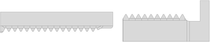
FIGURE 14. Cutting thread surface drawing.
As displayed in Figure 15, the mesh at the threads was divided more densely for accurate analysis.
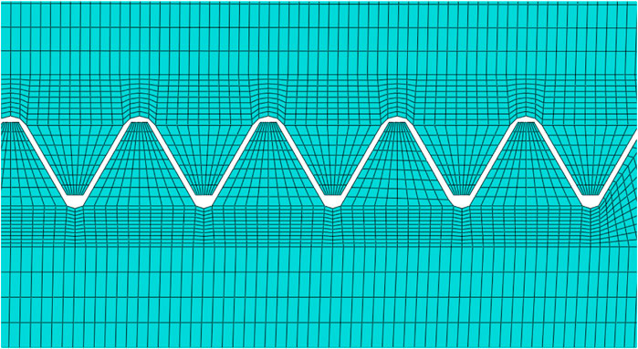
FIGURE 15. Mesh division diagram.
In the finite element analysis of the pumping rod threaded joint, the threaded contact surface was constrained to make the male and female threads work together. Then, a displacement constraint was applied to prevent the radial displacement of the threads during the loading process. Thereafter, the load was applied to one end of the rod coupling, and a uniform load was applied to the right shoulder of the rod head (Xu et al., 2017; Xu et al., 2019).
Figure 16 illustrates the equivalent force cloud on the thread contact surface obtained through finite element analysis.

FIGURE 16. Equivalent force cloud on the contact surface of the thread.
As displayed in Figure 16, the maximum equivalent force in operation at the threaded connection between the pumping rod head and the pumping rod coupling was observed at the tip of the threaded connection, with a maximum equivalent force of 419.5 MPa, and the equivalent force at other locations other than the threaded connection was smaller.
To analyze the effect of fatigue life of pumping rods with different thread root shapes, two different thread root shapes of rod head joints were simulated in this study, and the models are displayed in Figure 17, where the root shape of the left A thread is trapezoidal and the root shape of the right B thread is rounded.
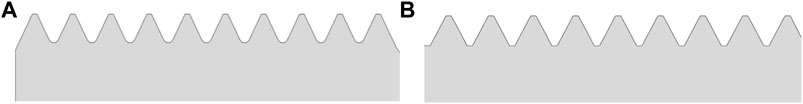
FIGURE 17. Thread root shape.
The shape of the thread root at the rod head had notable influence on the fatigue life of the rod in the broken pumping rods in the oil field site. The comparison between the stress clouds displayed in Figures 18, 19 revealed that stress was more obvious when the thread root shape was trapezoidal, and the maximum equivalent force value was greater than that of the pumping rod with a circular thread bottom because the trapezoidal shape facilitated stress concentration at the sharp corner of the root, resulting in the formation of a crack source and expansion of the crack until fracture (Jha and Arumugham, 2001).
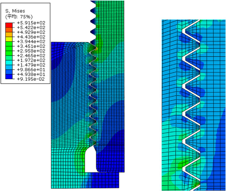
FIGURE 18. Trapezoidal stress cloud of the thread root.
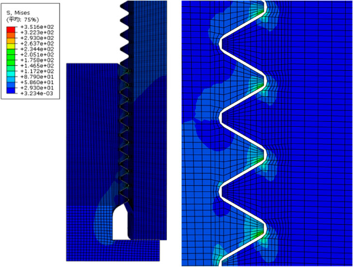
FIGURE 19. Circular stress cloud of the thread root.
4 Conclusion
Fatigue fracture samples from oilfield sites were analyzed for morphological characteristics, material composition, and hardness at fatigue fracture. The cross-sectional characteristics of the fatigue crack extension were summarized and used to infer the types of fatigue fracture and the influencing factors of the pumping rods. Fatigue fracture with large dimensional changes was primarily observed at certain sites of the pumping rod, for example, on the wrench side, in the transition area, and in threaded parts.
SolidWorks and ABAQUS software were used for modeling and static analysis of the pumping rod and threaded connection of the rod head. The primary stress in the rod body and the likelihood of fatigue damage were the highest near the header flange. In addition, no large deformation was observed along the axial direction during the operation of the pumping rod. The comparison of the stress cloud diagrams of different thread root shapes revealed that the stress readily concentrated at the root tip when the bottom of the thread groove was trapezoidal, thereby causing the formation of a crack source and extension of the crack until fracture.
Data availability statement
The original contributions presented in the study are included in the article/supplementary material, further inquiries can be directed to the corresponding author.
Author contributions
Conceptualization, WC; methodology, XM; validation, WL;formal analysis, SL; investigation, DZ; resources, HZ; datacuration, ZH.
Funding
This work is supported by the National Natural Science Foundation of China (grant no. 52074225). The Graduate Innovation and Practical Ability Training Project of Xi’an Shiyou University (No. YCS22111007).
Acknowledgments
The authors would like to thank all the reviewers who participated in the review, as well as MJEditor (www.mjeditor.com) for providing English editing services during the preparation of this manuscript.
Conflict of interest
WL, was empolyed by PetroChina Xinjiang Oilfield Company.
The remaining authors declare that the research was conducted in the absence of any commercial or financial relationships that could be construed as a potential conflict of interest.
Publisher’s note
All claims expressed in this article are solely those of the authors and do not necessarily represent those of their affiliated organizations, or those of the publisher, the editors and the reviewers. Any product that may be evaluated in this article, or claim that may be made by its manufacturer, is not guaranteed or endorsed by the publisher.
References
Bian, Y. J., Shi, W., Lao, J. Y., Chen, J., and Sun, S. L. (2011). The analysis on causes of rupture for a sucker rod made of 20CrMo alloy. Adv. Mat. Res. 1336, 626–630. doi:10.4028/www.scientific.net/amr.295-297.626
Chen, H., Luo, J., and Tang, K. (1994). Analysis of surface defects and cracks in pumping rods. Pet. Mach. 22 (7), 5.
Ding, W., Peng, Z. H., Zhang, Y., Ren, X., Zhang, X., and Wu, C. (2019). Fatigue analysis of HL grade pumping rods based on damage mechanics. Pet. Drill. Technol. 47 (04), 47–53. doi:10.11911/syztjs.2019041
Du, X. H., Li, Q., and Li, J. P. (2006). Fatigue strength of oil tubing in pumping engine wells and its fatigue fracture analysis. Pet. Min. Mach. 35 (6), 4. doi:10.3969/j.issn.1001-3482.2006.06.020
Galeev, A. S., Bikbulatova, G. I., Boltneva, Y. A., and Sabanov, S. L. (2020). Determination of lower sucker-rod breakage in wells equipped with sucker-rod pumps. IOP Conf. Ser. Mat. Sci. Eng. 860 (1), 012029. doi:10.1088/1757-899x/860/1/012029
Gibbs, S. G., and Neely, A. B. (1966). Computer diagnosis of down-hole conditions in sucker rod pumping wells. J. Petroleum Technol. 18 (01), 91–98. doi:10.2118/1165-PA
Hein, N. W., and Hermanson, D. E. (1993). A new look at sucker rod fatigue life. Houston, Texas: Society of Petroleum Engineers. doi:10.2118/26558-MS
Jha, A. K., and Arumugham, S. (2001). Metallographic analysis of embedded crack in electron beam welded austenitic stainless steel chemical storage tank. Eng. Fail. Anal. 8 (2), 157–166. doi:10.1016/s1350-6307(00)00003-0
Li, Z. H., Chen, H. P., and Luo, J. X. (1994a). Finite element analysis of stress intensity factor for elliptical cracks on sucker rod surface. Pet. Mach. 22 (12), 5.
Li, Q. (2006). Reliability study of surface cracks and remaining life of pumping rods. Harbin, Heilongjiang, China: Harbin Engineering University. doi:10.7666/d.y937152
Li, Q., Wei, J. L., Zhong, B. M., and Qin, H. (1994b). Study of remaining life of pumping rods. J. Daqing Petroleum Coll. 1994 (04), 53–56.
Lin, X. B., and Smith, R. A. (1999). Finite element modelling of fatigue crack growth of surface cracked plates: Part II: Crack shape change. Eng. Fract. Mech. 63 (5), 503–522. doi:10.1016/s0013-7944(99)00040-5
Ulmanu, V. V., and Ghofrani, R. (2001). Fatigue life prediction method for sucker rods based on local concept. Erdol Erdgas Kohle 117 (4), 189–195.
Wang, G. L., and Wei, J. Q. (1994). Study on the remaining life of pumping rod body and transition section. Mech. Pract. 16 (1), 4.
Xiang, Y., Lu, Z., and Liu, Y. (2010). Crack growth-based fatigue life prediction using an equivalent initial flaw model. Part I: Uniaxial loading. Int. J. Fatigue 32 (2), 341–349. doi:10.1016/j.ijfatigue.2009.07.011
Xu, J., Wu, K., Li, R., Li, Z., Li, J., Xu, Q., et al. (2019). Nanoscale pore size distribution effects on gas production from fractal shale rocks. Fractals 27 (08), 1950142. doi:10.1142/s0218348x19501421
Xu, J., Wu, K., Yang, S., Cao, J., and Chen, Z. (2017). “Nanoscale free gas transport in shale rocks: A hard-sphere based model,” in Paper presented at the SPE Unconventional Resources Conference, Calgary, Alberta, Canada, February 2017. doi:10.2118/185022-MS
Xu, S. B., and Yuan, X. Z. (1993). Life estimation of pumping rods with transverse cracks on the surface. Pet. Mach. 21 (5), 7.
Zhang, H., Liu, H. L., and Sun, Y. M. (2000). Finite element analysis of directional well rod pumping system. J. Petroleum 2000 (06), 102–106+32. doi:10.3321/j.issn:0253-2697.2000.06.019
Keywords: pumping rods, fatigue fracture, stress distribution, crack extension, finite element simulation
Citation: Cai W, Mo X, Li W, Liu S, Zhou D, Zhang H and Huang Z (2023) Study of fatigue damage of pumping rods based on finite element simulation. Front. Earth Sci. 10:1013167. doi: 10.3389/feart.2022.1013167
Received: 06 August 2022; Accepted: 28 September 2022;
Published: 11 January 2023.
Edited by:
Francesco Ascione, University of Salerno, ItalyCopyright © 2023 Cai, Mo, Li, Liu, Zhou, Zhang and Huang. This is an open-access article distributed under the terms of the Creative Commons Attribution License (CC BY). The use, distribution or reproduction in other forums is permitted, provided the original author(s) and the copyright owner(s) are credited and that the original publication in this journal is cited, in accordance with accepted academic practice. No use, distribution or reproduction is permitted which does not comply with these terms.
*Correspondence: Xiangyang Mo, eGlhbmd5YW5nbW85OEAxNjMuY29t; Wenbin Cai, Y2Fpd2VuYmluQHhzeXUuZWR1LmNu