 Min Yang
 Naifei Liu
 Ning Li1
95% of researchers rate our articles as excellent or good
Learn more about the work of our research integrity team to safeguard the quality of each article we publish.
Find out more
ORIGINAL RESEARCH article
Front. Earth Sci., 10 February 2022
Sec. Geohazards and Georisks
Volume 9 - 2021 | https://doi.org/10.3389/feart.2021.805378
This article is part of the Research TopicNew Development of Underground Energy Storage Using Mine SpaceView all 28 articles
During the operation period, disasters caused by the expansion of tunnel surrounding rock often occurs, but the understanding of this problem is still insufficient. This study investigated the disaster that occurred in the tunnel based on numerical simulation on a case in Dugongling, China. First, the main diseases, including lining cracks, pavement uplift and cable trench overturning and so on, of the tunnel were investigated in the field. According to the geological data, the expansion and softening of the surrounding rock was likely to be the main cause of lining cracking. Then, this paper proposed a formula for calculating the expansion force of expansive rock when the water content changes. Based on the expansion force calculation formula, the most severely damaged section was numerically analyzed, and the results were compared with the on-site monitoring data. According to the simulation results, the deformation of the surrounding rock and the stress of the supporting structure were studied. The research showed that the expansion and softening of the surrounding rock led to an increase in the load acting on the lining structure, which intensified the development of disasters. Finally, four reinforcement schemes were proposed and simulated, and the best reinforcement scheme was evaluated. The results of this study can provide a reference for the design and construction of this project and similar projects.
In recent years, with the vigorous development of a large number of construction projects, there have been varying degrees of disasters, such as deformation, lining cracking or leakage, in tunnel engineering during the construction or operation period. Some tunnels may even cause damage that endangers personal safety in the process of construction (Bian et al., 2016; Li et al., 2018; Liu et al., 2018; Dong et al., 2021; Fan et al., 2021; Yu et al., 2021). Among them, tunnel engineering disasters caused by expansive surrounding rock have been very common.
Swelling rock is a special soft rock that expands and softens with water, shrinks and disintegrates after water loss which is different from other rocks (Fan et al., 2019,2020; Liu et al., 2020a, 2020b; He et al., 2021a, He et al., 2021b; Kang et al., 2021; Zhang et al., 2021a). It has special engineering characteristics and easily causes tunnel disasters, which has a great impact on project cost and safe operation (LiuShui et al., 2014; Tang and Tang, 2012; Selen et al., 2020; Vergara and Triantafyllidis, 2015).
Most laboratory tests and field observations have shown that considerable pressure can be generated when the expansion strain is prevented. For example, a large number of tunnels in Baden-Württemberg state (southwest Germany) expand, resulting in high uplift of the unreinforced tunnel floor and exerting strong expansion pressure in the tunnel with supports (Berdugo et al., 2009). The surrounding rock will be extruded into the tunnel or cause floor uplift with the passage of time. Great damage will be caused to the initial support or lining of the tunnel (Kovari et al., 1988; Oldecop and Alonso, 2012). Water is one of the important factors for the uplift of the bottom of the tunnel (Anagnostou G. and Kovári K. 1995; Butscher et al., 2011a; Butscher et al., 2011b).
In serious cases, an effort is made to prevent or impede the expansion strain through the stiff tunnel lining. The expansion pressure is often high enough to cause damage to the tunnel lining. Even a 30 cm thick concrete support was destroyed during construction along large tunnel sections due to shearing failure (Wittke-Gattermann and Wittke, 2004). However, for large-scale cases with diseases, it is necessary to conduct special research on the damage and propose corresponding treatment measures for these.
In view of the seriousness of tunnel accidents caused by such expansive rock diseases, many researchers have studied the mechanism and treatment measures of tunnels in recent decades (Ren et al., 2006; Cui et al., 2014; Isago N. et al., 2014; Liu et al., 2011a; Liu et al., 2011b; Liu et al., 2020c; Liu et al., 2020d). During the tunnel excavation of the Trasvasur tunnels (Canary Islands, Spain) (Pérez-Romero et al., 2007), found that it is advisable to seal off the excavation as soon as possible to prevent change due to the decompression of the swelling clay levels and the absorption of water from the tunnel itself. Researching the deformation mechanism of swelling rock (Zhang et al., 2021b; Isago et al., 2015; Oldecop and Alonso, 2012), it was found that these measures that was the implementation of bolts (Waldemar 2015; Jeong et al., 2015), reinforced linings (Li et al., 2019; Bilir and Sarıgül, 2021; Korzeniowski et al., 2015), allowable deformation to reduce expansion pressure measurement (Aksoy et al., 2012; Sun and Wang, 2011) and so on can greatly reduce the probability of large deformation of the tunnel. Currently, most of the research on the stability of the tunnel is focused on the deformation of the surrounding rock in the process of construction, while the research on secondary lining failure during tunnel operation is limited. Therefore, it is of great significance to conduct research on the disease during the tunnel operation period and then give proper reinforcement measures to ensure that the tunnel is restored to traffic as soon as possible.
According to the damage phenomenon of the Dugongling tunnel of the Changping Expressway in Shanxi Province, China, this study evaluated the disaster of the expansive rock tunnel during the operation period. According to the geological data, the expansion and softening of the surrounding rock was likely to be the main cause of lining cracking. Then, this paper proposed a formula for calculating the expansion force of expansive rock when the water content changes. Based on the expansion force calculation formula, the most severely damaged section was numerically analyzed, and the results were compared with the on-site monitoring data. Finally, the proposed reinforcement schemes were put forwards, and then the stress situation of the lining structure under each reinforcement treatment plan was studied to analyze. The results of this study can provide a reference for the design and construction of this project and similar projects.
The Dugongling Tunnel is a two-way four-lane highway tunnel. The total lengths of the left and right tunnels are 2,474 m and 2,515 m, respectively. The maximum depth of the left tunnel is 221 m. The maximum depth of the right tunnel is 231 m. Except for some imported sections, the distance between the left and right lines of the tunnel is more than 20 m. The tunnel was completed and started operation in 2013. During the construction period and after tunnel operation, the tunnel support structures were found to have varying degrees of disaster. The disaster characteristics were mainly represented by the uplift and cracking of the road surface in the tunnel, the overturning of cable trenches, and the cracking of the second line of the tunnel, which seriously affected the normal operation of the expressway.
Folds developed in the tunnel site, but the scale of folds is not large. The strata are locally deformed and are broad folds with small dip angles. The lithology of the tunnel site is mainly composed of Quaternary Holocene slope diluvial loess-like silty clay (Q4dl + pl), Quaternary Upper Pleistocene slope diluvial gravel (Q3dl + pl), and marlstone and limestone of the Middle Ordovician upper Majiagou Formation (O2S1 and O2S2). The longitudinal section of the engineering geology of the Dugongling left tunnel is shown in Figure 1. The tunneling site mainly includes gypsum, softening marlstone, abolished mining pits, karst, and other adverse hydrogeologies (Xu and Wang, 2019; Xu and Wang, 2020; Liu et al., 2020).
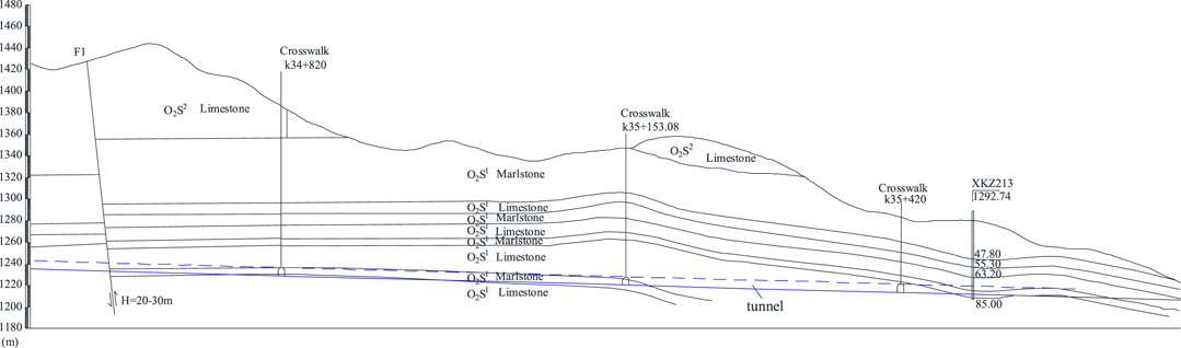
FIGURE 1. Geological profile.
The tunnel site has a temperate semiarid continental climate, with an average annual temperature of 9.2°C, of which January is the coldest with an average temperature of−5.8°C and July is the hottest with an average temperature of 22.6°C. In recent years, the average annual precipitation has been 592.33 mm. The maximum annual precipitation was 719.2 mm in 2013. The minimum annual precipitation was 491.8 mm in 2012. The main precipitation period is from July to September, accounting for 56–70% of the annual precipitation. The multiyear average evaporation is 1,699.5 mm, which is nearly three times the average precipitation over the years. The frost period is from early October to mid-April of the following year, with a frost-free period of 150 days, and the maximum frozen soil depth is approximately 1.0 m.
The inner wall of the tunnel has an upper layer of stagnant water, the aquifer lithology is limestone, and the lithology of the aquifer is marl or gypsum rock. The seasonal change in the upper layer of stagnant water is large. In the dry season, the maximum flow rate of water seepage at the bottom of the cable trench is only 60 L/d. Atmospheric precipitation is the only source of recharge for the upper layer. With the arrival of the rainy season, the amount of water seepage will gradually increase. In addition, the concentrated distribution of mining pits provides good access to surface water infiltration.
From april to July 2014, the Institute of Highway Research of the Ministry of Transport launched special test and assessment work on the expanded rock tunnel. The detection results showed that the left hole of the tunnel ZK34 + 300 ∼ ZK34 + 390, ZK34 + 605 ∼ ZK35 + 550 section was within the range of approximately 1,035 m, the right hole K34 + 430 ∼ K35 + 260 section was within the range of approximately 830 m, having varying degrees of disease phenomena. The lining crack length of the left tunnel was 1,580 m, which accounted for 63.86% of the total length. The lining crack length of the right tunnel was 850 m, which accounted for 33.80% of the total length. The uplift and cracking lengths of the pavement of the left and right tunnels were 207 m and 60 m, respectively. Among them, there were six uplifts and twelve cracks on the left road surface. There were two uplifts and nine cracks on the right road surface. The lengths of cable trench damage of the left and right tunnels were 391 m and 238.5 m, respectively. Photos of the failure characteristics of the tunnel are shown in Figure 2.
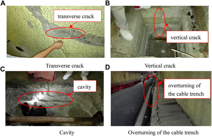
FIGURE 2. Photos of failure characteristics of the tunnel (A). Transverse crack (B). Vertical crack (C).Cavity (D). Overturning of the cable trench.
Based on the main diseases of the tunnel, section ZK35 + 045 of the left tunnel was selected as the research object. The lining of the ZK35 + 045 section was seriously damaged, and the cracks were densely distributed. Longitudinal cracks were mainly associated with several oblique cracks. The cracks were mainly distributed within 0 and 2 m of the sidewall, and the crack width was 0.1–5 mm. On the left side of the ZK35 + 045 section, there were longitudinal cracks with a length of 6 m. On the right sidewall, there were circumferential cracks with a length of 4.0 m, with a maximum of 6 cm on both sides of the arch waist and 13 cm on the road surface. The left and right pavements had different levels of voids.
Through the analysis of the geological conditions of the diseased holes and the drilling exploration results, it was considered that the main causes of the disease in the expansion rock tunnel are the following:
1) groundwater
The inner wall of the tunnel had an upper layer of stagnant water, the aquifer lithology is limestone, and the lithology of the aquifer is marl or gypsum rock. The seasonal change in the upper layer of stagnant water is large. In the dry season, the maximum flow rate of water seepage at the bottom of the cable trench was only 60 L/d. Atmospheric precipitation was the only source of recharge for the upper layer. With the arrival of the rainy season, the amount of water seepage will gradually increase. In addition, the concentrated distribution of mining pits provided good access to surface water infiltration. It was estimated that the direct infiltration of atmospheric precipitation through the pit was 31 m3/d.
2) geological structure
The cracks occurred in the surrounding rock of the diseased section, which is a marlstone and a gypsum interlayer of the Shangma Majiagou Formation of the Ordovician. The oblique S1 and S3 water storage structures caused the upper layer of stagnant water to pool in the diseased section.
3) softening of marl
According to relevant data from geological survey reports, the softening coefficient of marl was approximately 0.20–0.65, and the softening characteristics of marl were more obvious.
4) softening and expansion of the gypsum and anhydrite
The process of gypsum hydration to gypsum was gypsum expansion. During this process, expansion force will be generated on the tunnel lining; at the same time, gypsum softening will reduce the strength of the surrounding rock (Tang and Tang, 2012; LiuShui et al., 2014; Vergara and Triantafyllidis, 2016; Selen et al., 2020).
In view of the geological origin, this study concluded that the excavation of tunnels will gradually expose gypsum, anhydrite and marlstones to the environment, increasing the empty surface and redistributing the surrounding rock pressure, leading to the original recharge, runoff, and discharge routes of groundwater. All have changed, and the basement of the tunnel has become the drainage surface of the groundwater and the gallery corridor. Groundwater and tectonic actions provide favourable conditions for the softening and swelling of gypsum and limestone in the diseased section. Under the long-term action of groundwater, softening of marl, softening and expansion of gypsum and anhydrite destroy the lining of the surrounding rock, which is the main cause of disease.
The disasters of typical sections were simulated by using the software FINAL. The software has a unique function in geotechnical engineering. It has 32 types of units, which can simulate a variety of engineering problems, such as the dynamic and static problems of underground engineering, dam construction, slope engineering and foundation engineering. It has been used in many practical projects, such as the underground powerhouse of the Xiangjiaba Hydropower Station on the Jinsha River in China, the Heihe earth-rock dam in China and the left bank slope of Delsi Hydropower Station in the Republic of Ecuador.
Based on the theory of thermal expansion, this paper proposes the expansion force of expansive rock when the water content changes. In other words, the expansion force caused by the change in water content is equivalent to the expansion force caused by the change in temperature.
For expansive rocks of length
where
If rigid consolidation at both ends of the swelling rock cannot extend freely and cannot be bent and deformed, the elongation
where
Then, expansion occurs, and the equivalent expansion load is:
where
According to the provided geological map and survey report provided, the distribution of surrounding rock strata was determined. The tunnel cross-section layout is shown in Figure 3. The key points of the lining and pavement structure are shown in Figure 4. The detailed model of the finite element model and detailed details are shown in Figure 5. In this series of analyses, the finite element model includes wall rock units (LST units), excavation units (LST units), shotcrete unit units (BEAM6 units), and crack units (COJO units) (Li et al., 2000). The rock masses (wall rock and the excavation section) adopt an elastoplastic constitutive model and the Mohr-Colunmb strength criterion, while a linear elastic constitutive model was used for the shotcrete layer. The grouting effect was simulated by activating the prearranged curved beam element to simulate the shotcrete layer and lining structure, the system bolt and random bolt were simulated by the bar element, the grouting effect was simulated by improving the deformation modulus and strength parameters of the local surrounding rock of grouting, and the reinforcement effect of the reinforcing steel mesh and steel arch was simulated by improving the modulus and strength of concrete. The displacement boundary conditions permitted were that normal constraint down left and right boundary, adopts full constraints down the bottom boundary and freedom to displace along the top boundary.
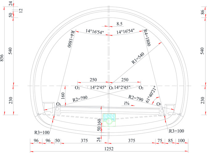
FIGURE 3. Arrangement diagram of the cross-section of the tunnel (unit: cm).
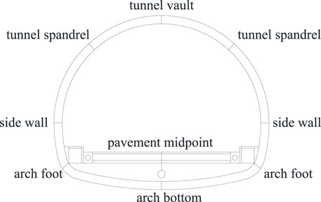
FIGURE 4. The key points of the lining and pavement structure.
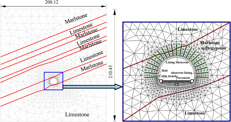
FIGURE 5. Finite element model and detail.
According to the relevant data and drawings of the tunnel disaster treatment, the main lithologies were marl and lime. According to the relevant geological drilling data and the relevant design manual of the tunnel, the basic physical and mechanical parameters of the surrounding rock are shown in Table 1.
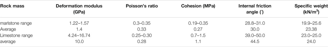
TABLE 1. Basic physical and mechanical parameters of surrounding rock.
According to the relevant data and the foregoing preliminaries, it was presumed that the disaster of the tunnel was caused by the softening and swelling of the marl. The disaster simulation needs to consider the softening and swelling characteristics of the marl. The main parameters include the softening coefficient, expansion coefficient, moisture content and softening expansion range. The parameters of marl softening expansion are selected as shown in Table 2. The material parameters of the supporting structure were mainly evaluated according to the design values of the code for the design of road tunnels (JTG D70-2004, 2004). The minimum reinforcement ratio of C25 reinforced concrete was calculated to be 0.2%, and its equivalent elastic modulus is 29.9 GPa. Other parameters were the same as C25 concrete. The elastic modulus of the sprayed concrete was calculated as per the actual steel arch frame and concrete area weight. The tensile strength of the anchor bolt was calculated according to the tensile strength of the HRB335 steel bar. The modulus of elasticity was measured by the longitudinal spacing equivalent. The values of the support materials and pavement structural parameters are shown in Table 3.

TABLE 2. Softening and expansion parameters of Marlstone.
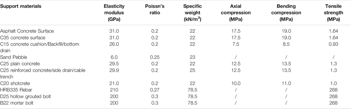
TABLE 3. Material parameters for support and pavement structures.
The expansion coefficient
where
The back analysis method has gradually become an important numerical calculation method in the process of survey, design and construction. Based on the above numerical model and initial parameters, the inversion analysis method is used to determine its parameters. The inversion analysis process was divided into three stages as follows:
1) Numerical simulation is carried out for the support structure of the tunnel and expansion softening process of the surrounding rock from geometric and mechanical aspects.
2) It tracks and analyses the stress field, deformation field and its distribution rule of surrounding rock when marlstone softens and expands, and the stress and deformation of the initial support and the secondary lining are analyzed.
3) The numerical simulation results are compared with the actual deformation and stress monitoring results. Then, the numerical model and parameters, forwards iteration and recursive analysis are fed back and adjusted. The value for the minimum difference between the numerical analysis result and the detection result is 5%.
In this section, the representative section of ZK35 + 045 was located in the ZK34 + 925∼ZK35 + 050 stretch of the left tunnel. The lining was seriously damaged, and the cracks are distributed densely. The failure of the lining was demonstrated by the back analysis method introduced above.
Taking the parameters in Tables 1–3 as the initial parameters of the simulation calculation, the deformation and cracking of the representative section lining and pavement were simulated by the established finite element analysis model. The simulated deformation and cracking of the lining and road surface are shown in Figure 6. Lining axial force and bending moment are shown in Figure 7.
FIGURE 6. Simulated lining deformation of the section of ZK35 + 045. (A) Axial force of the lining (unit: kN) (B) Bending moment of the lining (unit: kNm).
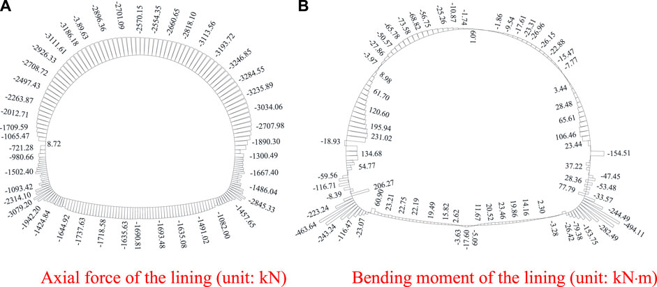
FIGURE 7. Lining axial force and bending moment.
In Figure 6, the road surface and the upside-down arches are uplifted, and the middle road surface uplift is relatively large. There were different levels of voids amongst the layers of the road surface. Cracks appear on both sides of the wall. Both the left and right sidewall and spandrel have converged deformation, and the sidewall deformation is relatively large. Both sides of the cable trench produce an inward tilt phenomenon. The simulated disaster law of the tunnel was basically consistent with the actual disaster characteristics on site.
To further verify the failure of the tunnel, according to the monitored deformation, the expansion coefficient and saturation of the surrounding rock were calculated. When the softening expansive range was 2 m, the softening coefficient was 0.20–0.54, the marl moisture content was 6.25% and the expansion coefficient was 0.125–0.138. The deformation and failure of the lining structure and road surface obtained by simulation are shown in Table 4.
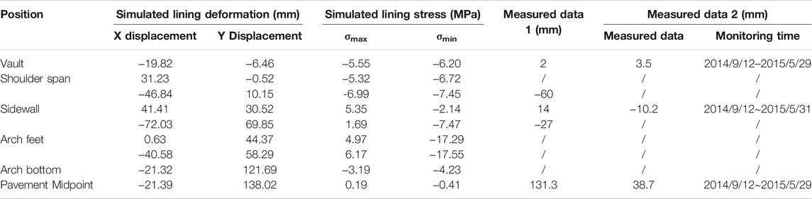
TABLE 4. Summary of stress and deformation of lining structure.
From Table 4, it can be seen that the maximum deformation is approximately 138.02 mm at the pavement midpoint, while the maximum deformation at the lining arch bottom was approximately 121.69 mm, reducing approximately 12% compared to the road surface. According to the measured deformation data at the site, the highest point of the road surface ridge was approximately 130 mm, which is in good agreement. Convergence deformations of approximately 41.41 and 72.03 mm were also produced in the left and right sidewalls (arch waist), respectively, which were basically consistent with the measured 6 cm. Tensile stresses appear on the arch feet, sidewalls and road surfaces, but the tensile stress at the pavement does not exceed 0.20 MPa. The tensile stress at the sidewalls and arches was as high as 6.20 MPa, far exceeding the ultimate tensile strength of C25 concrete, causing severe cracking damage at the sidewall. In addition, the tensile stress at the arch feet was the greatest. When reinforced, the enlargement leg of the bracket can be set at the arch feet.
From Table 4, it can be seen that the deformation of the road surface was approximately 38.7 mm from September 12, 2014, to May 31, 2015, and the convergence deformation of the sidewall was approximately 10.2 mm, which is approximately 25% of the road bump deformation. The left sidewall obtained by inversion was approximately 30% of the bump deformation of the road surfaces, which was caused by the late setting of convergence monitoring in the hole, resulting in the difference between the two values. In addition, the tunnel ridge deformation was approximately 130 mm, as measured by the tunnel laser cross-section detector, which was close to the 138.02 mm inversion value of the pavement midpoint. The actual convergent deformation at the arch shoulder was 60 mm, which was close to the inversion deformation of 46.84 mm. Therefore, the deformation simulation results were in good agreement with the actual deformation.
According to the results of the back analysis, the deformation and failure characteristics of the ZK35 + 045 section are extracted, and then the equivalent swelling and softening load of the surrounding rock on the lining structure when the lining was damaged was inverted by the integral method. When the disaster occurred, the maximum equivalent expansion softening load of the surrounding rock to the lining was located at the left wall and the right arch, which are 1.30–2.00 MPa. The rest were no more than 1.00 MPa, and the bottom of the arch is the minimum in Figure 8.
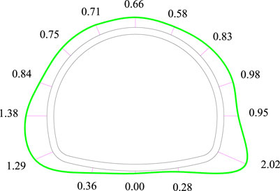
FIGURE 8. Expansion load of ZK35 + 045 (unit: MPa).
Combined with the original support scheme and engineering experience and based on the failure and parameter inversion results, several treatment measures were proposed. A numerical method was used to study the feasibility of the treatment scheme for representative sections under the effect of surrounding rock swelling and softening. The force situation and the effect of each reinforcement plan were evaluated.
Several treatment schemes are proposed, as shown in Table 5.
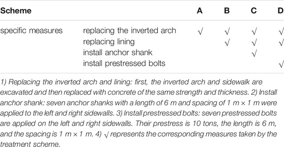
TABLE 5. Treatment schemes.
For tunnel defects, after the above four disposal schemes are adopted, the stress of the lining structure under the action of expansion force and surrounding rock softening is shown in Table 6.
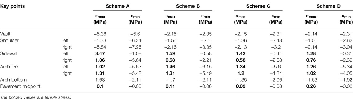
TABLE 6. Stresses at key points of the lining structure under different schemes.
Table 3 shows that when scheme A was adopted for the tunnel section, the stress of the lining structure undergoes a major change after arching, the tensile stress at various parts of the lining structure was significantly reduced during the later period of surrounding rock loads, and the most significant reduction was in the arch foot portion. Significantly (mainly due to the use of an enlarged bracket for the lining of the arch feet), after arching, the tensile stress at the left wall decreased from 5.35 to 3.47 MPa, nearly 35%; the tensile stress at the right wall was relatively small, and it decreased only 20%. The drop in the foot of both sides was up to 80%. However, the tensile stress at the left wall of the lining still exceeds the ultimate tensile strength of C25 concrete, and there was still the risk of cracking and destruction.
Compared with the tensile stresses of scheme A, when the section adopts scheme B, the reduction of the tensile stress at the left and right wall linings was most obvious, and the reduction was approximately 55%. The tensile stress at the left wall was approximately 1.59 MPa, and tensile stress at the right wall was approximately 0.58 MPa. The tensile stress at the arch feet was not significantly different from scheme A. Although the stress at the whole section was reduced to varying degrees after exchange and replacement, the tensile stress at the left wall and the arch feet were still greater than the ultimate tensile strength of the C25 concrete, and the tunnel safety was still insufficient.
Compared with the tensile stresses of scheme B, when the section adopts scheme C, the reduction of the tensile stress at the left and right wall linings was approximately 10%. The tensile stress at the left wall was approximately 1.42 MPa, and tensile stress at the right wall was approximately 0.58 MPa. The tensile stresses at the left and right arch feet were 1.34 and 1.20 MPa, respectively. Although the stress at the whole section has been reduced to varying degrees after exchange and replacement, the tensile stress at the left wall and the arch feet are still greater than the ultimate tensile strength of the C25 concrete, and the tunnel safety is still insufficient.
Compared with the tensile stresses of scheme C, when the section adopts scheme D, the reduction of the tensile stress of the lining at the left wall and the arch feet is approximately 10%, and the stress of the lining at the right wall slightly increased. After adding the prestressed bolts, the tensile stress at the left wall was approximately 1.28 MPa, and tensile stress at the right wall was approximately 0.76 MPa. The tensile stresses at the left and right arch feet were 1.26 and 1.02 MPa, respectively. In this reinforcement scheme, the tensile stress value of the full section of the lining structure was less than the design tensile strength of the C25 concrete, and the tunnel can operate safely under subsequent expansion and softening. The lining axial force and bending moment of scheme D are shown in Figure 9.
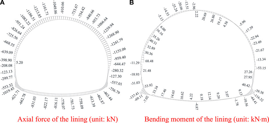
FIGURE 9. Lining axial force and bending moment of scheme D.
In summary, when section ZK35 + 045 adopts treatment plan D and steel reinforcement, the lining stress is less than the design tensile strength of C25 concrete, which meets the design requirements. Therefore, it is suggested that disposal scheme D be adopted as the final disposal scheme of this section.
Based on the investigation and analysis, the disaster of expansive rock tunnels in mountainous areas was studied by FINAL finite element software. The main conclusions were drawn.
1) Based on the theory of thermal expansion, a formula for calculating expansive force with water content of expansive rock was proposed.
2) As the marlstone expands and softens in water, the load on the lining structure increases and the tunnel disease intensifies. The simulated disaster confirmed this phenomenon. This tunnel’s disaster was mainly caused by the expansion and softening of the marlstone.
3) The inversed deformation is 130 mm at the pavement midpoint of ZK35 + 045, which was close to the measured value of 140 mm. The measured convergence deformation at the sidewall was 60 mm, which was consistent with the measured value of 70 mm.
4) According to the actual cracking situation, the progressive treatment scheme (A, B, C and D) was proposed. Scheme D (replacing the inverted arch and lining and installing prestressed bolts) met the design requirements and was recommended for practical disposal in Dugongling tunnel.
The original contributions presented in the study are included in the article/supplementary material further inquiries can be directed to the corresponding author.
Conceptualization, NL, methodology, GL; formal analysis, MY, NL, and GL, writing—original draft preparation, MY, writing—review and editing, MY, NL, NL, CX, GL, and MC, geologic information, CX, funding acquisition, NL.
This work is supported by the Postdoctoral Science Foundation (Grant No. 2019M663648), the Open Fund of State Key Laboratory of Road Engineering Safety and Health in Cold and High-altitude Regions (Grant No. YGY2020KYPT-03) and the National Natural Science Foundation of China (Grant Nos. 52179111, 51779207).
MC was employed by China Coal Technology Engineering Group Ecological Technology Co., Ltd.
The authors declare that this study received funding from State Key Laboratory of Road Engineering Safety and Health in Cold and High-altitude Regions, China Communications Construction Company First Highway Consultants Co., Ltd. The funder had the following involvement in the study: data analysis.
The remaining authors declare that the research was conducted in the absence of any commercial or financial relationships that could be construed as a potential conflict of interest.
All claims expressed in this article are solely those of the authors and do not necessarily represent those of their affiliated organizations, or those of the publisher, the editors and the reviewers. Any product that may be evaluated in this article, or claim that may be made by its manufacturer, is not guaranteed or endorsed by the publisher.
The authors would like to thank the Highway Science Research Institute of the Ministry of Transport for the support of the reported work.
Aksoy, C. O., Ogul, K., Topal, I., Ozer, S. C., Ozacar, V., and Posluk, E. (2012). Numerical Modeling of Non-deformable Support in Swelling and Squeezing Rock. Int. J. Rock Mech. Mining Sci. 52, 61–70. doi:10.1016/j.ijrmms.2012.02.008
Anagnostou, G., and Kovári, K. (1995). “Numerical Analysis of Tunnel Floor Heaves in Swelling Ground,” in Proceedings of the International Symposium on Numerical Models in Geomechanics (Davos), 451–456.
Berdugo, I., Alonso, E., Romero, E., Gens, A., and Albis, M. (2009). A Review of Expansive Phenomena in Wagenburg North Tunnel. Rev. Acad. Col Cienc Rev. Acad. Colomb Cienc 33 (129), 455–468.
Bian, K., Liu, J., Xiao, M., and Liu, Z. (2016). Cause Investigation and Verification of Lining Cracking of Bifurcation Tunnel at Huizhou Pumped Storage Power Station. Tunnelling Underground Space Tech. 54 (27), 123–134. doi:10.1016/j.tust.2015.10.030
Bilir, M. E., and Sarıgül, G. (2021). Stability Assessment of Terzili Tunnel in Swelling Rock Mass. Arab J. Geosci. 14 (11). doi:10.1007/S12517-021-07325-7
Butscher, C., Huggenberger, P., Zechner, E., and Einstein, H. H. (2011a). Relation between Hydrogeological Setting and Swelling Potential of clay-sulfate Rocks in Tunneling. Eng. Geology. 122 (3), 204–214. doi:10.1016/j.enggeo.2011.05.009
Butscher, C., Huggenberger, P., and Zechner, E. (2011b). Impact of Tunneling on Regional Groundwater Flow and Implications for Swelling of clay-sulfate Rocks. Eng. Geology. 117 (3), 198–206. doi:10.1016/j.enggeo.2010.10.018
Cui, L., Zheng, J-j., Zhang, R-j., and Zhang, W. (2014). Elastoplastic Solutions to Strain-Softening Behavior of Surrounding Rock Masses of Deep Circular Tunnels Considering Dilatancy Effect. Rock Soil Mech. 35 (4), 1987–1993. doi:10.16285/j.rsm.2014.04.027
Dong, Z., Kuo, C., Yin, J., Wen, S., Liu, G., and Gou, Y. (2021). Examination of Longitudinal Seismic Vulnerability of Shield Tunnels Utilizing Incremental Dynamic Analysis. Front. Earth Sci. 9. doi:10.3389/FEART.2021.779879
Fan, J., Liu, W., Jiang, D., Chen, J., William, T. N., and Daemen Jaak, J. K. (2020). Time Interval Effect in Triaxial Discontinuous Cyclic Compression Tests and Simulations for the Residual Stress in Rock Salt. Rock Mech. Rock Eng. doi:10.1007/s00603-020-02150-y
Fan, J., Jiang, D., Liu, W., Wu, F., Chen, J., and Daemen, J. (2019). Discontinuous Fatigue of Salt Rock with Low-Stress Intervals. Int. J. Rock Mech. Mining Sci. 115 (3), 77–86. doi:10.1016/j.ijrmms.2019.01.013
Fan, Y., Cui, X., Leng, Z., Zheng, J., Wang, F., and Xu, X. (2021). Rockburst Prediction from the Perspective of Energy Release: a Case Study of a Diversion Tunnel at Jinping II Hydropower Station. Front. Earth Sci. 9. doi:10.3389/FEART.2021.711706
He, M., Zhang, Z. Q., and Li, N. (2021a). Deep Convolutional Neural Networks-Based Method for Strength Parameter Prediction of Jointed Rock Mass Using Drilling Logging Data. Int. J. Geomechanics 21 (7). doi:10.1061/(ASCE)GM.1943-5622.0002074
He, M., Zhang, Z., Zhu, J., Li, N., Li, G., and Chen, Y. (2021b). Correlation between the Rockburst Proneness and Friction Characteristics of Rock Materials and a New Method for Rockburst Proneness Prediction: Field Demonstration. J. Pet. Sci. Eng. 205, 108997. doi:10.1016/J.PETROL.2021.108997
Isago, N., Kawata, K., Kusaka, A., Awaji, D., and Ishimura, T. (2014). “Deformation Mechanism of Tunnel under Swelling Rock Condition,” in ISRM International Symposium - 8th Asian Rock Mechanics Symposium (Japan), 1140–1147.
Isago, N., Kawata, K., Kusaka, A., and Ishimura, T. (2015). Long-term Deformation of Mountain Tunnel Lining and Ground under Swelling Rock Condition. Geomechanik Tunnelbau 8 (5), 380–386. doi:10.1002/geot.201500024
Jeong, Y.-Y., Kang, H.-M., Choi, S.-H., and Cho, S.-H. (2015). Dynamic Expansion Rock Bolt for Rapid Installing in Rocks. Geosystem Eng. 18 (2), 85–91. doi:10.1080/12269328.2014.1002635
JTG D70-2004 (2004). Code for Design of Road Tunnel. Chongqing: Ministry of Communications of the People's Republic of China.
Kang, Y., Fan, J., Jiang, D., and Li, Z. (2021). Influence of Geological and Environmental Factors on the Reconsolidation Behavior of fine Granular Salt. Nat. Resour. Res. 30 (1), 805–826. doi:10.1007/s11053-020-09732-1
Korzeniowski, W., Skrzypkowski, K., and Herezy, Ł. (2015). Laboratory Method for Evaluating the Characteristics of Expansion Rock Bolts Subjected to Axial Tension/Laboratoryjna Metoda Badania Charakterystyk Kotew Rozprężnych Poddanych Rozciąganiu Osiowemu. Arch. Mining Sci. 60 (1), 209–224. doi:10.1515/amsc-2015-0014
Kovari, K., Amstad, C., and Anagnostou, G. (1988). “Design/construction Methods-Tunnelling in Swelling Rocks,” in G Key Questions in Rock Mechanics (Minneapolis: Proc 29th US Symposium), 17–32. doi:10.1016/0148-9062(89)90655-4
Li, A., Xu, N., Dai, F., Gu, G., Hu, Z., and Liu, Y. (2018). Stability Analysis and Failure Mechanism of the Steeply Inclined Bedded Rock Masses Surrounding a Large Underground Opening. Tunnelling Underground Space Tech. 77 (3), 45–58. doi:10.1016/j.tust.2018.03.023
Li, N., Chen, B., Chen, F. X., and Zhang, P. (2000). Development and Application of the Austrian Software FINAL in China. J. Xi 1, 27–33. doi:10.19721/j.cnki.1671-8879.2000.01.007
Li, Q., Li, J., Zhang, J., Wang, C., Fang, K., Liu, L., et al. (2019). Numerical Simulation Analysis of New Steel Sets Used for Roadway Support in Coal Mines. Metals 9 (5), 606. doi:10.3390/met9050606
Liu, J. D., Li, Q. Y., and Gong, B. W. (2011a). Swelling Properties of Expansive Rock in Middle Route Project of South-To-North Water Diversion. Chin. J. Geotech Eng. 33 (5), 826–830.
Liu, N., Cui, L., Wang, Y., and Erol, Y. (2020). Analytical Assessment of Internal Stress in Cemented Paste Backfill. Adv. Mater. Sci. Eng. 2020, 1–13. doi:10.1155/2020/6666548
Liu, N., Li, N., Li, G., Zhang, Z., and Mu, Y. (2018). Deformation and Collapse Mechanisms of Water-Rich Soil Tunnels. Soil Mech. Found. Eng. 54 (6), 384–394. doi:10.1007/s11204-018-9485-5
Liu, N., Li, N., Xu, C., Li, G., Song, Z., and Yang, M. (2020d). Mechanism of Secondary Lining Cracking and its Simulation for the Dugongling Tunnel. Rock Mech. Rock Eng. 53 (10), 4539–4558. doi:10.1007/s00603-020-02183-3
Liu, W., Zhang, X., Fan, J., Zuo, J., Zhang, Z., and Chen, J. (2020). Study on the Mechanical Properties of Man-Made Salt Rock Samples with Impurities. J. Nat. Gas Sci. Eng. 84, 103683. doi:10.1016/j.jngse.2020.103683
Liu, W., Zhang, Z., Fan, J., Jiang, D., Li, Z., and Chen, J. (2020b). Research on Gas Leakage and Collapse in the Cavern Roof of Underground Natural Gas Storage in Thinly Bedded Salt Rocks. J. Energ. Storage 31, 101669. doi:10.1016/j.est.2020.101669
Liu, Y., Yu, H., and Wang, C. (2011b). Wang ChunleiResearch on Mechanism of Damage of Anhydrock in Dolomite Layer to Tunnel Structure. Rock Soil Mech. 32 (9), 2704–2708. doi:10.16285/j.rsm.2011.09.051
LiuShui, Q. S., Chen, Y. H., and LiuLiu, W. L. (2014). The Relation between Moisture Content and Share Strength of Swelling Soft Rock in the North of Xianfeng Town Open-Cast Coal. Amr 971-973 (971-973), 2168–2171. doi:10.4028/www.scientific.net/amr.971-973.2168
Oldecop, L., and Alonso, E. (2012). Modelling the Degradation and Swelling of Clayey Rocks Bearing Calcium-Sulphate. Int. J. Rock Mech. Mining Sci. 54, 90–102. doi:10.1016/j.ijrmms.2012.05.027
Pérez-Romero, J., Oteo, C. S., and de la Fuente, P. (2007). Design and Optimisation of the Lining of a Tunnel in the Presence of Expansive clay Levels. Tunnelling Underground Space Tech. 22 (1), 10–22. doi:10.1016/j.tust.2006.02.002
Ren, Q-y., Zhu, Y-w., Wang, J-t., and Liu, T-h. (2006). Numerical Modeling the Elastoplastic Constitutive Relation of Expansive Soil. Rock Soil Mech. 27 (10), 1699–1708. doi:10.16285/j.rsm.2006.10.011
Selen, L., PanthiPanthi, K. K., Vergara, M. R., and Mørk, M. B. (2020). Investigation on the Effect of Cyclic Moisture Change on Rock Swelling in Hydropower Water Tunnels. Rock Mech. Rock Eng. 54, 463–476. doi:10.1007/s00603-020-02266-1
Sun, J., and Wang, L. (2011). Numerical Simulation of Grooving Method for Floor Heave Control in Soft Rock Roadway. Mining Sci. Tech. (China) 21 (1), 49–56. doi:10.1016/j.mstc.2010.12.007
Tang, S. B., and Tang, C. A. (2012). Numerical Studies on Tunnel Floor Heave in Swelling Ground under Humid Conditions. Int. J. Rock Mech. Mining Sci. 55, 139–150. doi:10.1016/j.ijrmms.2012.07.007
Vergara, M. R., and Triantafyllidis, T. (2016). Influence of Water Content on the Mechanical Properties of an Argillaceous Swelling Rock. Rock Mech. Rock Eng. 49 (7), 2555–2568. doi:10.1007/s00603-016-0938-8
Vergara, M. R., and Triantafyllidis, T. (2015). Swelling Behavior of Volcanic Rocks under Cyclic Wetting and Drying. Int. J. Rock Mech. Mining Sci. 80, 231–240. doi:10.1016/j.ijrmms.2015.08.021
Wittke-Gattermann, P., and Wittke, M. (2004). Computation of Strains and Pressures for Tunnels in Swelling Rocks. Tunnelling Underground Space Tech. 19, 422–423. doi:10.1016/j.tust.2004.02.040
Xu, C., and Wang, H. L. (2019). Engineering Geological Characteristics and Engineering hazard Analysis of Dugongling Tunnel. Highw. transportation Sci. Technol. 36 (08), 93–99.
Xu, C., and Wang, H. L. (2020). Geological Characteristics of gypsum Bearing Marl and Analysis of Tunnel Engineering Influence. J. underground Space Eng. 16 (01), 227–233.
Yu, J., Zhang, Q., Xu, W., Wang, R., and Zhang, H. (2021). Study on Unloading Relaxation Characteristics of Columnar Jointed Rock Masses Based on Displacement Back Analysis. Front. Earth Sci. 9. doi:10.3389/FEART.2021.779537
Zhang, X., Liu, W., Jiang, D., Qiao, W., Liu, E., Zhang, N., et al. (2021a). Investigation on the Influences of Interlayer Contents on Stability and Usability of Energy Storage Caverns in Bedded Rock Salt. Energy 231. doi:10.1016/j.energy.2021.120968
Keywords: tunnel engineering, swelling rock, treatment measures, lining deformation, expansion and softening
Citation: Yang M, Liu N, Li N, Xu C, Li G and Cao M (2022) Failure Characteristics and Treatment Measures of Tunnels in Expansive Rock Stratum. Front. Earth Sci. 9:805378. doi: 10.3389/feart.2021.805378
Received: 30 October 2021; Accepted: 20 December 2021;
Published: 10 February 2022.
Edited by:
Jinyang Fan, Chongqing University, ChinaReviewed by:
Mingli Zhang, Lanzhou University of Technology, ChinaCopyright © 2022 Yang, Liu, Li, Xu, Li and Cao. This is an open-access article distributed under the terms of the Creative Commons Attribution License (CC BY). The use, distribution or reproduction in other forums is permitted, provided the original author(s) and the copyright owner(s) are credited and that the original publication in this journal is cited, in accordance with accepted academic practice. No use, distribution or reproduction is permitted which does not comply with these terms.
*Correspondence: Naifei Liu, bGl1bmFpZmVpQHhhdWF0LmVkdS5jbg==
Disclaimer: All claims expressed in this article are solely those of the authors and do not necessarily represent those of their affiliated organizations, or those of the publisher, the editors and the reviewers. Any product that may be evaluated in this article or claim that may be made by its manufacturer is not guaranteed or endorsed by the publisher.
Research integrity at Frontiers
Learn more about the work of our research integrity team to safeguard the quality of each article we publish.