 Mahfuzulhoq Chowdhury
- Chittagong University of Engineering and Technology, Chittagong, Bangladesh
Zero-touch networks (ZTNs) can provide autonomous network solutions by integrating software-based solutions for various emerging 5G and 6G applications. The current literature does not provide any suitable end-to-end network management and resource-slicing solutions for service function chaining (SFC) and user intent–based (time and cost preference) 6G/non-6G application execution over ZTNs enabled by mobile edge computing, network function virtualization, and software-defined networking. To tackle these challenges, this work initiates an end-to-end network management and user intent–aware intelligent network resource–slicing scheme for SFC-based 6G/non-6G application execution over ZTNs, taking into account various virtual and physical resources, task workloads, service requirements, and task numbers. The results depicted that at least 25.27% average task implementation delay gain, 6.15% energy gain, and 11.52% service monetary gain are realized in the proposed scheme over the compared schemes.
1 Introduction
With the growth of mobile devices, virtualized networks receive great attention from researchers due to their ability to provide flexibility and service agility for next-generation applications while incorporating a massive number of IoT devices (Ashraf et al., 2022). According to current statistics, by 2025, there will be over 27 billion IoT devices (Multiple Authors et al., 2022). One important point to note is that managing and orchestrating such a large number of IoT devices using traditional manual processes is impractical. Zero-touch networks (ZTNs) can address this issue by using software-based solutions instead of hardware-based platforms (Multiple Authors et al., 2022). A ZTN can be defined as a network that provides autonomous network and management operations, as well as end-to-end network programmability for various information and communication technology services, without requiring human intervention (Coronado et al., 2022). The primary goal of ZTNs is to enable autonomous services for current (5G) and future (6G) generation applications, cutting-edge technology infrastructure, computing, caching, routing, resource allocation, and self-healing facilities based on customer demands and available resources.
Currently, ZTNs face several challenges such as proper security measures for network management and application services, automated end-to-end solutions, network resource–slicing facilities for heterogeneous applications by taking into account diverse customer demands (e.g., time-saving and cost-saving demands), proper service coordination for different applications that require services from different technologies such as mobile edge computing (MEC), software-defined networking (SDN), network function virtualization (NFV), service function chaining (SFC), blockchain, federated learning (FL), and efficient resource and work node allocation, among others. To address the high communication latency and bandwidth shortage limitations of traditional centralized cloud computing technology, MEC is viewed as an edge cloud computing technology that offers cloud and storage services at the user network’s edge (Tseng et al., 2021). SDN is a networking approach that uses centralized software-based controllers or applications to configure all of the underlying hardware or network elements (VMware, 2024). Instead of using proprietary hardware elements for network services [e.g., firewall (FW) and network address translation (NAT)], NFV technology provides virtualized network services through the use of virtual machines (Red Hat, 2024). NFV enables service providers to run multiple virtual network functions (VNFs) on different servers rather than rely on a dedicated server. SDN and NFV technology both support SFC (a connected chain of network services within an application), which allows connected service functions to be completed sequentially (Chen et al., 2022).
There is currently some work being done in the area of ZTNs. Theodorou et al. (2021) used blockchain technology to automate ZTN service assurance in multi-domain network slicing. However, they only looked at bandwidth prediction accuracy results, not different types of 5G and 6G application execution performance results. Coronado et al. (2022) presented a survey article on various enabling technologies for ZTN-based automated network management solutions, such as SDN, NFV, and artificial intelligence techniques. The authors also discussed some research challenges for ZTN, such as SFC for 5G/6G applications, network slicing and resource allocation, proper work node selection, security and privacy, and appropriate computing and caching solutions for various applications, among others. Xu et al. (2022) developed a Markov game and a reinforcement learning–based optimization solution for wireless power control and spectrum selection in industrial applications. Angui et al. (2022) discussed the challenges for automated cloud radio access networks (RANs) in 6G ZTNs, which included resource discovery, antenna capability, network coverage issues, and computation resource availability. Grasso et al. (2021) proposed a ZTN management technique based on deep reinforcement learning (DRL) for load balancing and computation offloading in an unmanned aerial vehicle (UAV)–aided edge network. Yoshino et al. (2021) developed a multi-service provisioning test bed for zero-touch optical access networks, utilizing access network virtualization technologies and pluggable module-type optical line terminals (OLTs). They did not, however, look into the network slicing–based resource orchestration problem or conduct a performance analysis for 5G and 6G application execution.
Ksentini (2021) investigated the resource management and orchestration operation of ZTN with heterogeneous network slices. However, their work faces significant challenges in terms of quality of service (QoS) guarantee, scalability, and sustainability due to the presence of multiple cross-platforms and domains in B5G/6G systems, which include the RAN network, core network, edge cloud, and remote cloud. Dalgkitsis et al. (2020) proposed a DRL-based VNF placement solution for zero-touch–based 5G networks that incorporate both SDN and NFV technologies. Demchenko et al. (2015) explored automated network services for zero-touch cloud computing applications, such as network slicing and resource management. Mohammadpour et al. (2022) used a ZTN to automate monitoring and traffic generation for virtualized network services. Niboucha et al. (2023) created a zero-touch security management framework for massive machine-type communications (mMTC) network slices in 5G, which include DDoS attack detection. Basu et al. (2022) used a machine learning–based ZTN management framework with dynamic VNF allocation and SFC embedding for 5G applications. Luque-Schempp et al. (2022) developed an automata learning–based smart controller with suitable configuration to predict and satisfy the requirements of time sensitive networking traffic in ZTNs. El Houda et al. (2022) examined the performance of an ensemble learning–based intrusion detection model in SDN-based zero-touch smart grid systems. Wang et al. (2022) describes a framework for optimizing UAV formation and tracking to capture 360-degree views of moving targets in ZTN-based VR applications. Martini et al. (2022) created an intent-based service chain layer for dynamically deploying service chain paths over SDN-based edge cloud networks. Intent-based networking refers to a dynamic or intended approach (i.e., digitized, automated) for network configuration and problem solving rather than a manual process. To reduce network and computation latency, Sebrechts et al. (2022) proposed using a fog-native approach rather than a remote cloud-based approach for executing intent-based workflows. Abbas et al. (2020) used a deep-learning model (e.g., generative adversarial neural network) to manage core and RAN resources.
To that end, SDN is a critical enabling technology for executing user requirements–based tasks over a ZTN. Okwuibe et al. (2021) proposed an SDN-based resource orchestration scheme for industrial IoT application execution, facilitating collaboration among edge and remote cloud networks. In addition to SDN, Wang et al. (2021) identified NFV as a key technology for automated service execution in 5G and 6G applications. However, in order to meet the requirements for SFC in SDN/NFV networks, VNFs must be properly selected and deployed. To get the most out of an SDN-/NFV-based network with the least amount of delay and cost, SFC (logical or virtual chain) properly connects different service functions one after the other during application execution. These authors demonstrated an SFC with the following VNF execution order: 1) FW, 2) deep packet inspection, 3) encryption, 4) data monitoring, and 5) decryption. Zhong et al. (2019) proposed an SFC solution for NFV-enabled inter-data center networks that considers service financial costs and reliability. However, they did not look into service costs or dependable performance for both 5G and 6G applications.
Lin et al. (2023) present integer linear programming (ILP)–based heuristic algorithms for energy-efficient resource allocation and SFC embedding in NFV networks. Wei et al. (2022) used a quantum genetic algorithm to solve a multi-objective optimization problem for delay-aware resource provisioning and parallel SFC orchestration in NFV networks. To predict the traffic flow rate of SFC in NFV networks, Gu et al. (2019) incorporated an online learning algorithm–based VNF scaling. Pei et al. (2020) proposed a deep learning algorithm for two-phase VNF selection and chaining activities to generate efficient routing paths in SDN/NFV networks. Saha et al. (2020) developed an ILP problem to optimize the number of NFV nodes and IoT devices in SDN/NFV networks. Chen et al. (2022) proposed a Q-learning–based SFC embedding scheme for SDN/NFV-enabled wireless networks to reduce network delay and increase SFC acceptance ratio.
The above discussion mentions network slicing and resource management as critical research challenges for intent-based ZTNs. To offer low latency and high resiliency, Thiruvasagam et al. (2021) proposed a genetic algorithm–based network resource–slicing scheme for multi-connectivity–based and MEC-enabled 5G networks. Feng et al. (2020) developed a Lyapunov optimization–based short- and long-timescale bandwidth allocation scheme for 5G ultra-reliable low-latency communications (URLLC) and enhanced mobile broadband (eMBB) application execution to provide energy and cost-efficient solutions for RANs. To reduce latency and energy consumption, Tang et al. (2021) proposed a DRL slice selection for computation offloading operations in vehicular networks. Brik et al. (2020) proposed an FL-based approach for predicting service-oriented key performance indicators (KPIs) for 5G networks. Chergui et al. (2021) presented a statistical FL method for slice-level KPI prediction in energy-efficient 6G networks.
However, previous research on ZTNs with or without cloud, SDN, and NFV technologies did not present a task execution performance analysis that considered both 6G and non-6G/5G applications. For example, Salameh et al. (2022) mentioned three main types of 5G applications: (i) eMBB (e.g., video streaming and immersive gaming applications via HoloLens), (ii) mMTC (e.g., smart video surveillance and smart agriculture via IoT and cloud computing technologies such as optimal plans for irrigation or fertilizer frequency determination based on plant health), and (iii) URLLC (e.g., industrial automation, circular manufacturing, and collaborative human–robot interaction-based applications). Alwis et al. (2021) identified and discussed several promising 6G applications with their task execution requirements. They categorized 6G applications as follows: (i) further-eMBB (FeMBB) [e.g., metaverse-based social avatar applications, holographic telepresence, and haptic feedback-based extended reality (XR) applications], (ii) long-distance high-mobility communications (LDHMC) (e.g., high-speed railway applications, space travel, and deep-sea sightseeing applications), (iii) extremely URLLC (eURLLC) application (e.g., FL-based fully automated driving applications), (iv) extremely low-power communication (ELPC)–type application (e.g., blockchain, IoT, and digital twin–based electronic healthcare), (v) ultra-massive machine-type communications (umMTC) (e.g., wireless power transfer, electronic vehicle charging, and brain–computer interface-based applications such as wheelchair control by using brain signals) application (Rico-Palomo et al., 2022).
1.1 Gaps or limitations in existing studies
Based on the previous research-work discussion, it is clear that earlier related works did not investigate a proper intent-aware and service requirement–aware intelligent network resource–slicing scheme for SFC based on both 6G and non-6G application execution over SDN-, NFV-, and MEC-driven ZTN. Without an appropriate network resource–slicing scheme and proper virtual resource node selection, SFC-based 6G and non-6G applications over the ZTN may experience significant SFC execution time latency, user energy expense latency for SFC execution, service execution monetary cost, lower QoS satisfaction ratio, and low throughput, among other things.
Furthermore, the question of how to coordinate SDN and NFV technology, as well as edge cloud technology, for SFC-based 6G and non-6G application execution in ZTNs is beyond their scope. Furthermore, their analyses excluded time-first and cost-first intent-based 6G and non-6G service provisioning for SDN- and NFV-based ZTNs. Furthermore, previous research did not present any suitable network infrastructure for time-first and cost-first service-aware resource slicing for SFC-based 6G and non-6G application execution over SDN- and NFV-based ZTNs. Existing works did not investigate latency, QoS satisfaction, and cost performance analysis by taking SFC for multiple 6G applications such as metaverse-based social avatar applications, holographic telepresence, haptic feedback-based XR applications, high-speed railway applications, FL-based fully automated driving applications, blockchain, IoT, and digital twin–based electronic healthcare, wireless power transfer, electronic vehicle charging, and brain–computer interface-based wheelchair control by using brain signals.
Similarly, the existing works did not investigate performance analysis for multiple non-6G applications such as video streaming, immersive gaming applications via holoLens, smart video surveillance, and smart agriculture via IoT and cloud computing technologies such as optimal plans for irrigation or fertilizer frequency determination based on plant health, or industrial automation work such as circular manufacturing or collaborative human–robot interaction-based applications.
The SFC-based task implementation delay analysis associated with various existing works did not take into account different delays such as network inauguration phase delay, user request and resource gathering phase delay, network slicing phase delay, and task work realization delay (all of which include computation, caching, communication, and waiting time). Existing research did not provide a suitable mathematical model that included task implementation delay, energy expense, QoS guarantee ratio, achievable throughput, service execution monetary cost for users and service providers, service provider profit, user and service provider welfare, alive node number, and survived energy amount for users, among other things.
1.2 Motivations and contributions of our work
To tackle these existing issues, this article proposes a service requirement–aware intelligent network resource–slicing scheme (i.e., accelerator) for SFC-based multiple 6G and non-6G application execution over SDN-, NFV-, and MEC-based and intent-driven ZTNs. Previous research works did not create an end-to-end network management system with proper resource allocation procedures for 6G and non-6G application execution over SDN- and NFV-based ZTNs. SDN- and NFV-based 6G and non-6G applications require proper resource allocation and network systems to meet diverse requirements, such as low task implementation deadlines, time preferences, and cost preferences. Because of a lack of intelligent network architecture and resource-slicing schemes, the current scheme incurs significant task implementation delays, energy costs, and service execution expenses.
The aforementioned limitation motivates us to present a resource-slicing scheme that maximizes the task implementation delay gain, energy gain, and monetary cost gain for SFC-based multiple 6G and non-6G application executions over the ZTN. Our work’s main innovation and contribution is that it develops a resource-slicing scheme (for both communication and computation resources) that considers both time-priority and cost-priority service requirements for various applications. Furthermore, unlike previous research, this paper investigates ZTN performance for both 6G and non-6G application execution by taking different resource and task types into consideration. For the first time, it brings together SDN, NFV, blockchain, IoT, and MEC technologies to enable ZTN-based application execution. The significant contributions of this work are mentioned below:
• This work inaugurates an intent-based (time preference first and cost preference first) network resource–slicing scheme for different SFC-based 6G and non-6G applications by considering different virtual and physical resources, digital twin, blockchain, edge computing, caching, and FL services and different SFC workloads, different task data sizes, different service execution budgets, energy values, service execution deadlines, task count, and available resource statuses.
• This work develops an intelligent virtual and physical work node (e.g., NFV, cloud server) assignment along with a network resource (bandwidth) assignment scheme for different 6G application execution (e.g., metaverse, holographic telepresence, XR applications, FL, blockchain, IoT, digital twin, and brain–computer interface-based applications) and different non-6G application execution (e.g., video streaming, smart video surveillance, and industrial automation) over MEC-, SDN-, and NFV-enabled ZTNs.
• This work provides an intelligent network model that incorporates SDN technology, NFV technology, blockchain, digital twin, FL, MEC technology, and wired and wireless networks, along with different user devices [e.g., mobile phones, XR devices, holographic telepresence screens, haptic feedback sensors or devices, brain sensors, health sensors, robots, IoT devices, video cameras, and electric vehicles).
• The primary goal of the proposed resource-slicing scheme is to maximize task implementation delay gain, energy gain, and monetary gain for various 6G and non-6G application executions over a ZTN. This work introduces an accelerator algorithm that coordinates application execution steps and appropriate resource selection (time slot, work nodes, computing, and communication link) for both time-first and cost-first SFC application (6G and non-6G) execution over ZTNs.
• This paper delivers a mathematical analysis model for 6G and non-6G application execution over ZTNs, which includes task implementation delay, energy expense, QoS guarantee ratio, achievable throughput, service execution monetary cost for users and service providers, service provider profit, and user and service provider welfare. Unlike previous works, our task implementation delay includes additional delays such as network inauguration, user request and resource gathering, network slicing, and task work realization delay (such as computation, caching, communication, and waiting delay).
• To demonstrate the suitability, the proposed accelerator scheme simulation results (for both time-first and cost-first schemes) are presented with proper analysis in the Simulation results and analysis section, along with a performance comparison with the traditional scheme.
Next, Section 2 includes the related works. The proposed accelerator scheme is depicted in Section 3 with an algorithm, working steps, and network model. Section 4 holds the mathematical analysis model that includes different performance metrics. The simulation results are investigated in Section 5. The conclusion associated with the proposed scheme is highlighted in Section 6.
2 Related works
This section discusses the existing literature on SDN-, NFV-, and MEC-enabled ZTNs. Ma et al. (2022) developed a zero-touch management scheme for IoT devices using digital twins. Brik et al. (2020) proposed a FL-based approach to predict network slice performance for 5G applications. Boškov et al. (2020) introduced a software-enabled access point and a Bluetooth-based automated zero-touch service provisioning solution for IoT devices.
To enable automated network fault management services, Sousa and Rothenberg (2021) discussed a closed loop–based ZTN management framework. Yoshino et al. (2021) discussed the feasibility of automated line opening and zero-touch provisioning–based multiple service provisioning with pluggable module-type OLT for access network virtualization. Liyanage et al. (2022) presented a detailed survey regarding the ZTN and service management concept, architectures, components, and key technical areas. Shaghaghi et al. (2021) discussed a DRL-based and age-of-information–aware failure recovery scheme for an NFV-enabled ZTN. Coronado et al. (2022) presented a survey regarding ZTN management solutions that included both automated and zero-touch management techniques for both wireless and mobile networks. To provide scalable and fast ZTN-slicing operations and service provisioning, Roy et al. (2022) presented a cloud-native and service-level agreement (SLA)–driven stochastic FL policy. To ensure proper execution of industrial IoT applications, Lin et al. (2022) presented a machine learning-based end-to-end solution for ZTN-based traffic steering and fault management issues. Sebrechts et al. (2022) developed a fog native architecture for microservice application provisioning and workflow management in intent-based networking.
To design loss functions in regression tasks, Collet et al. (2022) presented a deep learning-based prediction scheme for intent-based networking. Okwuibe et al. (2021) presented constraint satisfaction problem solving based on resource orchestration scheme, in which SDN is used as an orchestrator for industrial IoT application execution in collaborative edge cloud networks. Alwis et al. (2021) discussed a detailed survey regarding 6G applications, requirements, technologies, 6G enablers, and research challenges, among others. Rico-Palomo et al. (2022) discussed several new services for the 6G ecosystem, such as FeMBB, LDHMC, eURLLC, ELPC, and umMTC. Salameh et al. (2022) discussed different challenges, technologies, and applications related to both 5G and 6G networks. Song et al. (2020) discussed constrained Markov decision process (CMDP)–based network-slicing solutions for different types of 5G applications (e.g., eMBB, URLLC, and mMTC). To maximize the network’s long-term throughput, Suh et al. (2022) investigated a DRL-based network slicing solution for B5G applications. Adhikari et al. (2022) proposed a cybertwin-driven DRL scheme for dynamic resource provisioning in 6G edge computing networks. Cao et al. (2021) presented a resource availability–based SFC scheduling scheme for 6G application execution with virtualization. Alsabah et al. (2021) discussed a comprehensive survey regarding the 6G vision, key enabling technologies, key applications, and technical challenges for the 6G wireless communication networks. Thiruvasagam et al. (2021) presented a failure-resilient resource orchestration and network-slicing scheme for multi-connectivity and MEC-empowered 5G networks.
To guarantee latency and reliability, Feng et al. (2020) discussed a Lyapunov optimization–based resource scheduling scheme for 5G URLLC and eMBB services. To optimize latency and energy cost, Tang et al. (2021) presented a DRL-based slice selection and computation offloading framework for vehicular networks. By leveraging both SDN and NFV technologies, Hermosilla et al. (2020) presented a dynamic security management framework in MEC-powered UAV networks. Sun et al. (2020) developed a breadth-first search–based SFC optimization scheme. Lin et al. (2023) presented an energy-aware SFC-embedding scheme in NFV networks. Zhang et al. (2019) investigated the longest common sequence (LCS)–based flexible framework for SFC executions. To maximize the utility value for SFC embedding, a Markov chain–based optimization scheme was presented by Lin et al. (2022). Saha et al. (2023) utilized the Brown–Gibson model for efficient cloud service provider selection for different IT-based applications. Tianran et al. (2023) presented a reputation-based collaborative intrusion detection system (IDS) using blockchain technology. Huang et al. (2023) used fuzzy C-means clustering and a bat optimization algorithm for optimizing IoT-based smart electronic services. Chowdhury (2022) highlighted an energy-harvesting and blockchain-aware healthcare task coordination policy for IoT-assisted networks. Fathalla et al. (2022) presented a preemption choice–based physical machine allocation policy for cloud computing tasks. Chen et al. (2023) discussed a non-cooperative game-based computation task offloading policy for MEC environments. A multi-objective–based evolutionary algorithm was presented by Wang et al. (2022) for joint task offloading operations, power, and resource allocation in MEC-based network. Chen et al. (2019) presented a distributed deep learning–based parameter updating and synchronization model for a video surveillance system. Hu et al. (2021) formulated a coalition game for multi-customer resource procurement in the cloud computing environment. However, most of the aforementioned related works (e.g., that of Fathalla et al., 2022; Chen et al., 2023; Wang et al., 2022; Chen et al., 2019; Hu et al., 2021) are limited only to a single type of MEC task rather than both SFC-based 6G and non-6G application execution. They also did not utilize multiple technologies such as SDN, NFV, IoT, and MEC at the same time for different intents (e.g., time-first and cost-first) based on resource-slicing policies for ZTN-based 6G and non-6G application execution.
To predict the VNF flow rate, Gu et al. (2019) proposed an online learning algorithm for SFC execution. To minimize the total SFC embedding cost, Chen et al. (2021) formulated mixed ILP (MILP)–based VNF mapping and scheduling problems in edge cloud networks. Zhou et al. (2019) presented a bidirectional offloading scheme for SFC- and NFV-enabled space–air–ground integrated networks. To minimize the latency of all SFC requests and satisfy the service level agreements, Tamim et al. (2020) utilized an MILP model for SFC placements in NFV networks. To lower the rejection rate in terms of SFC request execution, Mohamad et al. (2022) discussed a prediction-aware SFC placement and VNF-sharing scheme. To satisfy the application execution requirements, Tseng et al. (2021) utilized the MEC server for VNF placement and scheduling decisions for augmented reality application execution in NFV networks. Hantouti et al. (2020) presented a detailed survey regarding SFC execution in 5G networks that includes several use cases, key enabling technologies, and potential research problems. Zahoor et al. (2022) identified different research challenges and potential solutions associated with network slicing for 5G applications. Zahoor et al. (2023) discussed the performance evaluation of hypervisor-based virtualization technologies for NFV deployment.
Table 1 depicts the comparison between the proposed scheme and existing schemes. The existing work did not investigate both 6G and non-6G application execution for MEC-, SDN-, and NFV-empowered ZTNs. They also did not investigate proper resource-slicing schemes by taking into account both service requirements and different intents (time-first and cost-first schemes) for ZTN-based applications. In differing from the existing works, this article presents a service-aware and double intent–based (time-first and cost-first) network resource–slicing scheme for SFC-based 6G and non-6G application execution over MEC-, SDN-, and NFV-empowered ZTNs.
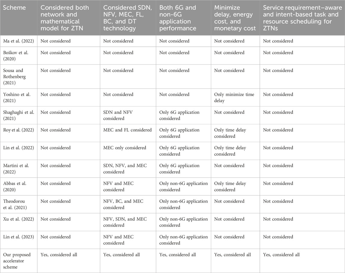
Table 1. Comparison with existing works.
Algorithm 1.Proposed accelerator-based algorithm.
1: for network slicing manager do
2: sends the network’s first beacon message to users.
3: gets UCR (internet connectivity request) and UMSR (service registration message) from the users and dispatches URR (internet connectivity response) and UAA (user authentication and service registration response) to the users
4: broadcasts SMTRS message (user slot assign for task request dispatch) to users and receives request messages during UTR slot from users
5: sends RURS (request for resource update) message to resource and work nodes and gets resource-update response message (URIS) from work nodes. Sends ISDR message (inter SDN/slicing controllers request message for task/resource node information) and receives ISRES message (response message) from other slicing managers
6: computes resource slicing and SFC scheduling information during CNRS slot and sends NSD message to users (selected time slot and resource information) and RSD (resource/time slot information) to selected work nodes
7: if SFC request = = 6G application then
8: executes before the non-6G application. Offers resources to the time-first task before the cost-first priority task for all 6G tasks (FeMBB, eURLLC, umMTC, LDHMC, and ELPC).
9: again sorts each time-first/cost-first priority task based on their shortest task time limit.
10:selects the best resources (physical and virtual work node with network communication link) for each sorted time-first priority task with the lowest predicted task implementation delay (min
11: else if SFC request = = non-6G application then
12: executes after the 6G application. Offers resources to the time-first task request first before the cost-first priority-based task for all non-6G task types (URLLC, eMBB, and mMTC).
13: again sorts each time-first/cost-first priority task based on their shortest task execution time limit. Selects the best resources for each sorted time-first priority task with lowest predicted task implementation delay (min
14: end if
15: Go to step 1
16: end for
3 Proposed accelerator-based network slicing for ZTN
3.1 Network model and considerations
Figure 1 represents the network model for the SFC-based 6G and non-6G application execution over the SDN-/NFV-empowered ZTN. The virtualized work nodes (e.g., MEC and caching devices, FL server, blockchain server, NFV server, and digital twin server) have resided near the cellular base station. The service requests that are from user nodes (e.g., robot, mobile phone, electric vehicles, video camera, brain–computer sensors, XR users, IoT-based electronic health users, haptic devices such as haptic jackets or glass, and holographic screens) are located within the coverage range of cellular base stations and wireless access points. The SFC task request applications are generated by the user devices and dispatched to the network slicing manager at the cellular base station. The network slicing manager decides the best work node selection (e.g., virtual and physical work nodes) for each user task implementation. The user devices can be attached to the internet via both the wireless cellular base station and WLAN access point devices. Three different types of wireless communication links are available. They are terahertz communication (IEEE 802.15.3d based, bandwidth of 5 THz, link range 1–10 m), microwave communication (IEEE 802.11b based, link range 1–300 m, bandwidth 7.2 GHz), and millimeter/millimeter wave (mmWave) link (IEEE 802.11ad based, link range 1–50 m, bandwidth 1.25 GHz). Along with the cellular link, the user devices can transfer their data by using the WLAN link (IEEE 802.11be-based data transfer, 2.4/5/6 GHz radio frequency). The best wireless communication link is selected by the network slicing manager for data transfer based on link availability and the data transfer rate.
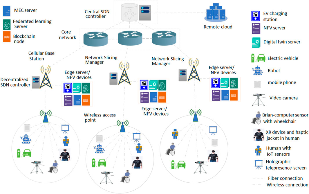
Figure 1. Proposed SDN-/NFV-empowered ZTN model for 6G and non-6G application execution.
The decentralized SDN controller is located near the cellular base station (network slicing manager) that offers NFV monitoring, routing path selection, automatic network device configuration, and node/link failure monitoring purposes. The central SDN controller is located three or four hops away from the decentralized SDN controller. The central SDN controller monitors and manages the network resource status and device configuration centrally. The decentralized SDN controller (at the cellular base station) can perform their work by receiving the central SDN controller’s command and can contact the central SDN controller regarding any query associated with the network node, resource status, or remote services. The connectivity between the cellular base station/core network and the core network/central SDN controller is done via an IEEE 802.3cd-based dedicated fiber link. Similarly, connectivity between the cellular base station/central SDN controller and edge servers/remote cloud servers is offered via the IEEE 802.3cd-based fiber communication link. The edge server located near the cellular base station contains different types of virtualized devices, such as MEC and caching servers, FL servers, blockchain devices, digital twin servers, and NFV servers. The electronic vehicle (EV) charging station can be located within the cellular base station/WLAN access point communication range. In this paper, initially, the SFC task execution request is dispatched from the user nodes to the network slicing manager. The slicing manager collects the resource and task information from the work nodes (virtual and physical devices) and users. After that, the slicing manager selects a suitable communication time slot along with the best work nodes (virtual and physical work nodes) for users’ different 6G and non-6G application executions. After the task processing or implementation, the users receive the task result from the work nodes via the wireless or wired communication links.
3.2 Accelerator-based network-slicing scheme and work node selection scheme
This section elaborately discusses all steps associated with the proposed network slicing scheme. Figure 2A highlights the timing model, and Algorithm 1 shows the proposed accelerator-based work node selection scheme. Figure 2B shows the overall pipeline of the proposed model. As shown in Figure 2A, our proposed accelerator scheme includes four phases. The first phase is the network inauguration phase. The second phase is the user request and resource information gathering phase. The third phase is the network slicing phase. The fourth phase is a different 6G- and non-6G-based task realization or implementation phase. At the first network inauguration phase, the network slicing manager (cellular base station) first transmits the beacon messages (NIB messages) to the surrounding users. The users who receive the beacon messages send or transfer an internet connectivity request message (UCR) to the network-slicing devices. The network slicing manager sends an internet connectivity response (URR) to users. Next, the users prepare and send a network service registration (UMSR) message to the slicing manager that includes registration requests for different services such as blockchain, computing, caching, FL, SFC execution, EV charging and sharing, and digital twin–based prediction services. After that, the network slicing manager dispatches user authentication and registration response messages (UAA) to the users. Moreover, the slicing manager schedules a control slot for users for their 6G and non-6G application requests and dispatches SMTRS (scheduling message task request control slot) to the users.
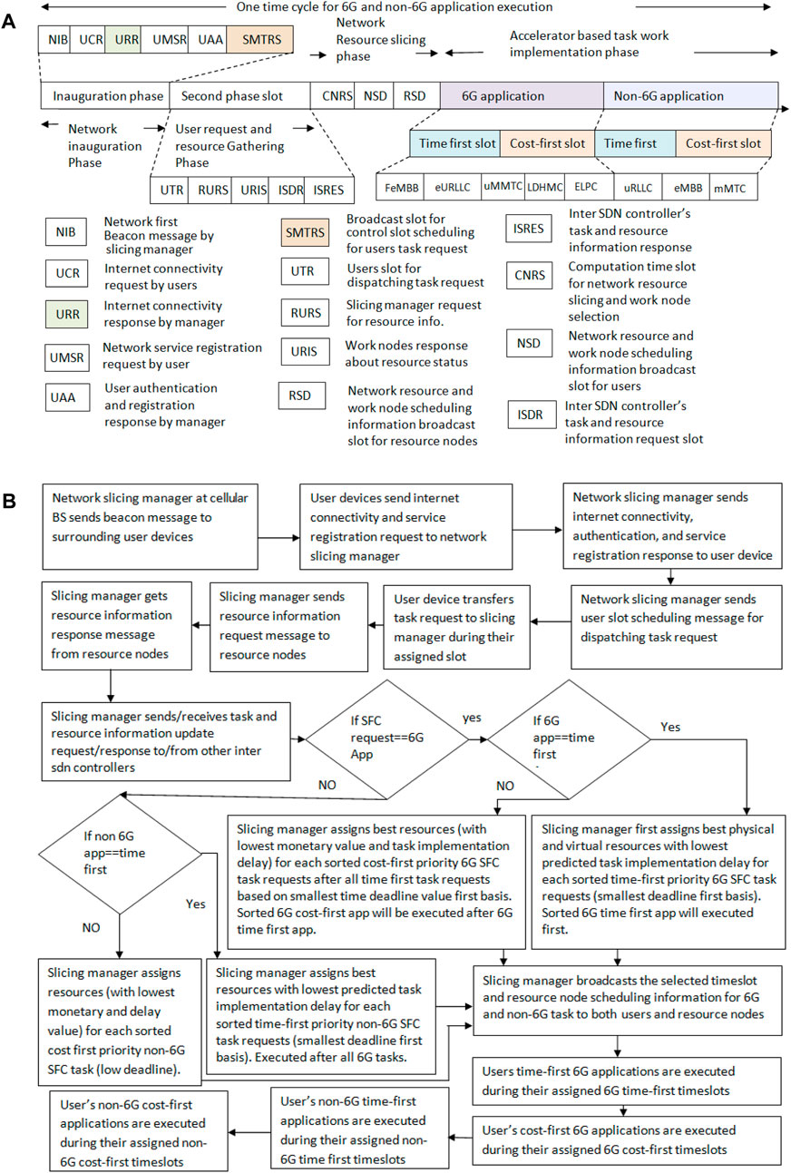
Figure 2. (A) Proposed timing model; (B) overall pipeline of the proposed model.
Next, the second phase of our proposed scheme becomes operable (i.e., the user request and resource gathering phases). After that, the user dispatches or sends the 6G and non-6G application or task execution service requests to the slicing manager during their UTR (user slot for dispatching task requests) slot. The scheduling manager next dispatches a RURS (resource information request slot) message to the resource nodes or workers. The work nodes and resource devices send a URIS message (a work node response about their resource status) to the slicing manager. It can be noted that only the URIS message within a time deadline will be accepted. After the time deadline, the remaining URIS message will not be accepted. Similarly, RURS messages are sent to multiple work nodes and resource nodes. If one RURS message is unsuccessful, the slicing manager will try to send another RURS message within the RURS message exchange time deadline (set before the time cycle begins). If all the RURS messages are unsuccessful, the slicing manager will rely on its previous resource information for scheduling (step 5 of Algorithm 1). Similarly, if one URIS message is unsuccessful, the slicing manager will rely on the other nodes' URIS response messages for resource scheduling.
Next, the host decentralized SDN controller that resides within the network slicing manager sends an ISDR message (inter SDN controller query message about information like resource link or work node and routing information, task, and resource scheduling information) to the other decentralized SDN controller and central SDN controller. The other SDN controller sends an ISRES message (other SDN controllers respond to a query like task scheduling information for a network slicing node) about their resource scheduling information and other resource link or node status. After that, the third phase starts (i.e., the network resource–slicing phase). In this phase, by using the collected information (e.g., different resource node status, other slicing managers' task scheduling information, available virtual and physical resources, and 6G and non-6G task requests), the host slicing manager at the cellular base station completes the SFC, work node, task scheduling, and resource-slice assignment process during the CNRS slot time (i.e., the computation time slot for network resource slicing and work node selection for 6G and non-6G applications). In this work, two different schemes are used for resource slicing. The first one is a time-first scheme and the second one is a cost-first scheme. The user can select one approach during their task request message dispatch process. For the time-first scheme, the suitable virtual/physical work node and wired/wireless link combination are selected for each SFC task request based on the lowest predicted task implementation delay (min
For the cost-first scheme, the suitable virtual/physical work node and wired/wireless link combination are selected for each SFC task request based on the lowest predicted user service execution monetary value (min
It can be noted that in this work, different 6G and non-6G application execution performances are analyzed. The considered 6G applications are metaverse-based social avatar applications, holographic telepresence, haptic feedback-based XR applications, high-speed railway applications, FL-based fully automated driving applications, blockchain, IoT, and digital twin–based electronic healthcare, wireless power transfer, electronic vehicle charging, and brain–computer interface-based wheelchair control by using brain signals. The considered 6G applications are video streaming, immersive gaming applications via the holoLens, smart video surveillance, and smart agriculture via IoT and cloud computing technologies, such as optimal plans for irrigation or fertilizer frequency determination based on plant health, and industrial automation work such as circular manufacturing or collaborative human–robot interaction-based applications.
For example, during a 6G application time slot (i.e., brain–computer interaction-based wheelchair movement application), the selected work node and users have to perform several activities. Initially, the user’s task request is transferred to the slicing manager for the brain–computer interaction-based application. Before receiving the task request, the slicing manager executes different VNFs, such as FW, digital packet inspection (DPI), and NAT. Next, the slicing manager sends the task implementation instructions to the selected work nodes (users’ head sensors and sensing devices, MEC server) and user devices. After receiving the task instructions, the head-sensing devices capture the users’ brain signals [via electroencephalography (EEG) and functional magnetic resonance imaging (fMRI)] and offload the captured data to the MEC server for processing. Before receiving the dispatched data, the MEC server executes two VNFs, such as IDS and NAT. Next, the MEC/virtual server performs processing of brain signals from the collected data and signals, feature extraction, pattern recognition, and translation commands (from brain signals). After that, the MEC/virtual server sends a processed command to the user’s wheelchair. Before receiving the processed result, the wheelchair device performs FW, NAT, and IDS operations. Then, the user’s wheelchair device operates or moves based on MEC-processed commands from the brain signal. After the completion of these activities, the brain–computer interaction-based wheelchair movement work is complete. Furthermore, during a non-6G application time slot (e.g., IoT-based smart agriculture assistance), the work node and users have to perform several activities. Initially, the user’s task request is transferred to the slicing manager for the IoT-based smart agriculture assistance application. Before receiving the task request, the slicing manager executes different VNFs, such as FW, DPI, and NAT. Next, the slicing manager sends the task implementation instructions to the selected work nodes (IoT sensors and sensing devices in the agriculture field, MEC server) and user devices. After receiving the task instructions, the IoT devices and sensors collect different crop and environment data (e.g., crop image, humidity, soil data, moisture, temperature) and dispatch or offload the captured data to the MEC server for processing. Before receiving the dispatched data, the MEC server executes two VNF operations, such as IDS and NAT. Next, the MEC/virtual server performs captured data processing and produces irrigation and fertilization frequency plans for farmers based on the crop data. After that, the MEC/virtual server sends processed data (task-processing results regarding irrigation/fertilization frequency plan) to the user devices. Before receiving the processed result, the user device performs FW and IDS VNF operations. Next, the MEC-processed task result data are visualized on the screen or used on a mobile device. It can be noted that in Figures 2B, if any message dispatch activity or task execution is unsuccessful, the slicing manager will consider only successful tasks or messages. The unsuccessful task will not be included in the performance evaluation process. For resource scheduling, the slicing manager will rely on its own information along with the work node information.
4 Mathematical model
This section presents the important performance metrics calculation model with a proper explanation. The considered performance metrics are task implementation delay, energy expense, service execution monetary cost for users and service providers, service providers' profit, and survived energy amount for users. First, we will discuss the average task implementation delay.
4.1 Task implementation delay
The task implementation delay calculation
where
Next, the total task work realization delay
where
Our first 6G task is metaverse-based social avatar creation and avatar interaction (e.g., 6G FeMBB use case). The SFC delay (task realization delay) associated with social avatar–based metaverse task
where
Next, this paper investigates the SFC delay (task realization delay)
where
Next, this paper investigates the SFC delay (task realization delay) associated with EV charging related to 6G applications using Eq. 7.
where
Next, this paper investigates the SFC delay (task realization delay)
where
After that, this paper investigates the SFC delay (task realization delay)
where
Next, this paper investigates the SFC delay (task realization delay)
Next, this paper investigates the SFC delay (task realization delay)
where
Next, this paper investigates the SFC delay (task realization delay)
Next, the article investigates the SFC delay (task realization delay)
Next, this paper discusses the SFC delay (task realization delay)
Now, this paper calculates the SFC delay
Next, we compute the SFC delay
Last, we present the SFC delay
4.2 User energy usage value for task implementation
The user device energy usage value
where yts and ycs are the total implemented users’ time-saving priority tasks and cost-saving priority tasks, respectively.
4.3 QoS guarantee ratio
The QoS guarantee ratio
The QoS guarantee ratio
where
4.4 Maximum achievable throughput
The maximum achievable throughput
where
4.5 Users' service execution monetary cost
The service execution cost for users’ task implementation
where yts and ycs are the total implemented users’ time-saving priority tasks and cost-saving priority tasks, respectively.
4.6 Internet service providers' and cloud providers' profit
The total task execution profit for internet service providers (ISPs) and that for the cloud providers can be determined by taking the difference
where
4.7 User and service providers' welfare value
User welfare for task implementation value
where
4.8 User's survived energy
The user’s average survived energy
4.9 Total number of capable or alive user devices
The total number of capable or alive user devices
5 Simulation results and analysis
Section 5 presents the comparison results of (i) the proposed time-first accelerator scheme with a minimum predicted computation delay, communication delay, and waiting delay–based network resource slicing, (ii) the proposed cost-first accelerator scheme with a minimum predicted service execution monetary cost–based network resource slicing, (iii) the traditional minimum communication delay–based network resource–slicing scheme (e.g., Sun et al., 2020; Siasi et al., 2020; Marotta et al., 2017; Cai et al., 2022; Przybylski et al., 2021), and (iv) the traditional computational power–based work node selection with casual task scheduling scheme (e.g., Zhang et al., 2015; Ma et al., 2022; Demchenko et al., 2015; Angui et al., 2022). The detailed simulation parameters (e.g., data size, workload, monetary cost, energy cost, and deadline) and the values associated with the different SFC tasks are discussed in Table 2.
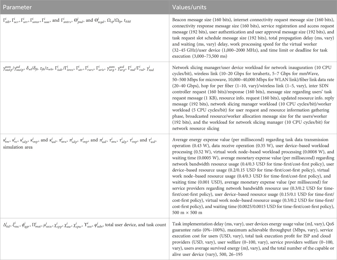
Table 2. Simulation notations or parameters with values.
For simulation, the total value of task count is varied between 26 and 195. The task data amount associated with users' task request, server-to-server dispatched amount during VNF processing, task instruction with virtual/physical work node selection are 1,024 bits, 512 bits, and 256 bits, respectively. The data size associated with metaverse-based avatar interaction task input, users' first and second avatar conversation data, holographic telepresence task input, MEC processed holographic task output, EV charging task input, MEC processed EV charging task output are chosen random basis within 1–20 KB, 1–20 KB, 1–10 MB, 1–10 MB, and 1–5 KB range, respectively. The distance from starting to the charging station point for EV movement, client devices' own movement speed, charging requirement, and available charge value data are varied randomly within 100–500 m, 50–80 m/s, 0.15–0.6 KWh, and 0.2–0.6 KWh, respectively. The battery depletion threshold, battery capacity, and EV charging/discharging rate are 0.15, 50 KWh, and 45 KW, respectively. The data size associated with offloaded brain–computer interaction task, MEC-processed brain–computer interaction task result, offloaded haptic feedback-based gaming task, MEC-processed haptic feedback task result, offloaded human–robot interaction-based automation task, human users' processed task result for automation task, robots' second offloaded task data, and robots' second inspection data to the human users' device are chosen on random basis within 5–50 KB, 5–50 KB, 1–20 MB, 1–20 MB, 1–20 KB, 1–20 KB, and 1–20 KB range, respectively. The task data amount for MEC-processed result in high-speed railway task, offloaded amount for high-speed railway task, transfer from users to the receiver device, global deep learning model for FL task, offloaded data size for FL task, finally updated global deep learning model, initial blockchain registration operation, e-healthcare task input, digital twin–based processed result, doctor device–processed result, transferred block data size, transferred verified block data size, a user accessed e-healthcare task result, and downloaded video files are varied between 1 and 10 KB, 1–10 KB, 1–50 KB, 1–15 MB, 1–5 MB, 1–15 MB, 1–15 MB, 5–25 KB, 5–25 KB, 5–25 KB, 5–25 KB, 5–25 KB, and 5–25 KB, respectively. The task data size for offloaded XR-based education learning task, MEC-processed XR task result, offloaded smart agriculture task, MEC-processed smart agriculture task result, offloaded video surveillance task, MEC-processed video surveillance task result are chosen on random basis within 1–10 MB, 1–10 MB, 1–20 KB, 1–20 KB, and 1–5 MB, respectively.
The workload amount for FW, DPI, and NAT operation, client device–based avatar creation data capture, IDS, avatar creation by MEC, avatar movement, client device–based conversation data capture for avatar, virtual node–based avatar conversation message–playing operation, second client device–based conversation data capture, and virtual node–based second avatar conversation message–playing operation are 300, 300, 300, 100, 300, 500, 100, 100, 500, and 100 CPU cycles/bit, respectively. The distance from one avatar to another during movement are chosen randomly between 5 and 500 m. The workload amount for client device–based holographic task data capture, MEC servers' holographic data processing, receiver device–based holographic data processing, receiver device–based holographic data visualization, client device–based electronic vehicle task data capture, EV charging task data processing at MEC server, brain data capture work, brain–computer interaction task data processing at MEC server, receiver device–based wheelchair movement operation, entering game state, haptic feedback task input data collection, haptic input task data processing at MEC server, and receiver device–based haptic feedback reception are 50, 1 K, 50, 10, 100, 1 K, 1 K, 1 K, 1 K, 50, 500, 1 K, and 10 CPU cycles/bit, respectively. The workload amount for supplying raw material to robots, user manufacturing operations, checking robots' work by using human devices, robot-based rechecking operations, checking robots’ final work by using human devices, base station selection at the MEC server, load balancing operations, encryption operations at the receiver base stations, decryption operations, task output data displays at the receiver, client device–based road data captures, local model data training, global model updates, MEC blockchain server work and local client during preliminary blockchains, user e-healthcare data collection, e-healthcare task data processing at digital twin, e-healthcare task data processing at doctor devices, e-healthcare block creation, block verification, ledger update, receiver device–based e-health data display are 100, 100, 50, 100, 50, 1,000, 200, 200, 200, 100, 50, 50, 1 K, 100, 100, 100, 1 K, 100, 100, 100, 100, and 10 CPU cycles/bit, respectively. The workload amount for cache lookup, XR task input data collection, XR task data processing at MEC, receiver device during XR data reception, IoT device for task input data collection, agriculture task processing at MEC, receiver device–based agriculture data reception, video surveillance input data collection, video surveillance task data processing at MEC, video surveillance task resultant data reception are 50, 50, 1 K, 10, 500, 1 K, 100, 50, 1 K, and 10 CPU cycles/bit, respectively.
In Figure 3A, this work first compares the average task implementation delay (i.e., average task execution time) of the proposed time-first and cost-first scheme against the traditional scheme (minimum communication delay–based worker selection) by varying the task count number. The task implementation delay is defined by taking the sum of all delays associated with task initiation and task execution completion. As we can see from the figure, when the task count value is smaller, the task implementation delay is smaller in all proposed and compared schemes. The increment in task count value produces a higher task implementation delay in all proposed and compared schemes. The figure shows that the proposed time-first accelerator scheme produces the lowest task implementation delay when compared with the others. Although the proposed cost-first scheme receives the highest task implementation delay, and the compared (minimum communication delay) scheme offers the second-lowest task implementation delay. The proposed time-first accelerator scheme adopts the best virtual and physical worker selection with a minimum predicted computation delay, communication delay, and waiting delay for their SFC-based application execution. The proposed time-first scheme also ensures a task QoS guarantee by offering worker and resource allocation based on the smallest deadline on a task-first basis. On the contrary, the proposed cost-first scheme adopts worker and resource allocation based on their lowest payment costs, thus receiving the third place. If multiple workers or resources offer the same lowest cost, the best worker or communication resource is selected in the cost-first scheme based on their highest computation capability or link data rate. The compared scheme selects a worker or resource for application execution based on the lowest communication delay (i.e., the nearby worker or resource), thus receiving the second place. Due to its only communication delay–based selection, the task execution in the compared scheme may receive the second-highest waiting delay. The task implementation delay is the highest in the cost-first scheme because workers or resources with the lowest monetary cost are preferred (e.g., remote cloud), thus experiencing the highest computation delay, waiting delay, and communication delay. In Figure 3A, if the task number is 195, the average task implementation delay for the proposed time-first, compared scheme (minimum communication delay), and proposed cost-first scheme is 33,658 ms, 42,164 ms, and 51,441 ms, respectively.
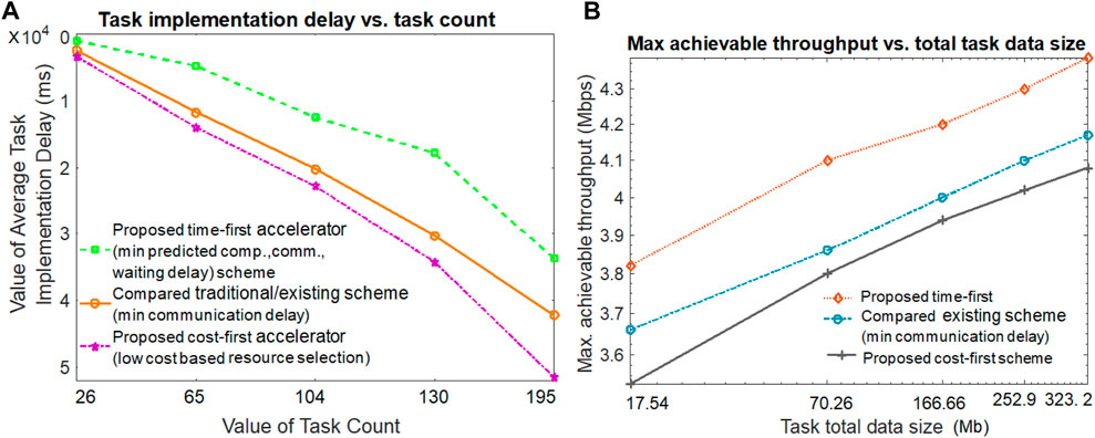
Figure 3. Task implementation delay and throughput achievable value.
The maximum achievable throughput for both proposed and compared methods by varying task total data size values is investigated in Figure 3B. The throughput value is calculated by taking the ratio of the total exchanged task data value and the makespan task execution delay value. Figure 3B hints that a large amount of the total task data exchange produces a higher achievable throughput value than its smaller amount task data counterparts in both the proposed and compared schemes. Hence, the task implementation makespan delay is the lowest in the proposed time-first scheme; it produces the highest achievable throughput value. Due to the second- and third-highest task implementation makespan delay values, the compared scheme (minimum communication delay) and proposed cost-first offer the second-best and third-best throughput values, respectively. In Figure 3B, if the task data size number is 252.9 Mb, the achievable throughput for the proposed time-first, compared scheme (minimum communication delay), and proposed cost-first scheme are 4.34 Mbps, 4.10 Mbps, and 3.95 Mbps, respectively.
Figure 4A examines the QoS guarantee ratio of our proposed scheme by varying the value of the time limit. It is shown in Figure 4A that when the task execution time limit is higher, the QoS guarantee ratio is also large in all three schemes (proposed and compared). When the task execution time limit is smaller, the QoS guarantee ratio is also smaller in both the proposed and compared schemes. The proposed time-first scheme offers the highest QoS guarantee ratio. This is because it experiences lower computation, communication, and waiting delays for task execution than the other compared schemes due to its appropriate resource and worker selection scheme. The cost-first scheme receives the third position as it experiences the highest computation, communication, and waiting delay for task execution compared to other schemes. The cost-first scheme receives the second position as it experiences the second-best computation and waiting delay for task execution. From Figure 4A, it can be noted that when the task time limit value is 73,500 ms, the achievable QoS guarantee ratios of the proposed time-first scheme, compared scheme (minimum communication delay), and proposed cost-first scheme are 100%, 86.15%, and 74.87%, respectively.
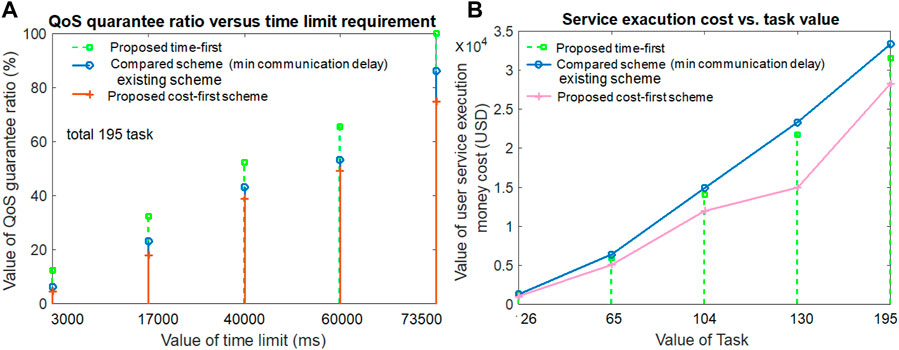
Figure 4. Service quality guarantee ratio and user money or service execution cost.
The service execution cost value for both the proposed scheme and the compared scheme by varying the value of the task number is highlighted in Figure 4B. The figure visualizes that a large amount of task execution requires the highest amount of service execution cost for users, and a small amount of task execution requires a comparatively lower amount of service execution payment cost for users in all three compared schemes. However, the proposed cost-first scheme allocates resources with the smallest monetary cost for task execution, thus offering better service execution cost results than others. The proposed time-first scheme requires resources for a smaller amount of time than the compared (minimum communication delay) scheme. Thus, the proposed time-first scheme gives the second-best service execution cost for task execution, and the compared scheme gives the third-best service execution cost results. From Figure 4B, it is shown that when the task value is 104, the service execution monetary payment cost for the proposed time-first scheme, compared scheme (minimum communication delay), and proposed cost-first scheme is 14,050 USD, 14,900 USD, and 11,960 USD, respectively.
Figure 5A gives the user’s energy usage or expense value by varying the task data size for all three schemes. Figure 5A notes that the increment in task data size value requires a higher energy usage value than its smaller task data size counterparts in all three schemes. For both large and small task data sizes, the proposed time-first scheme requires the smallest user device energy usage value for task execution compared to both cost-first and compared schemes. The main reason behind this result is that the proposed time-first scheme experiences a lower amount of task implementation delay, thus requiring a smaller amount of energy than others. Although the cost-first scheme experiences a large amount of task implementation delay, thus requiring a higher amount of energy than others, the compared scheme (minimum communication delay) gives the second-best energy expense or usage value due to its second-best task implementation delay results. From Figure 5A, it can be deduced that when the task data size value is 323.2 Mb, the energy usage cost for the proposed time-first scheme, compared scheme (minimum communication delay), and proposed cost-first scheme is 27,626 mJ, 29,326 mJ, and 30,200 MJ, respectively.
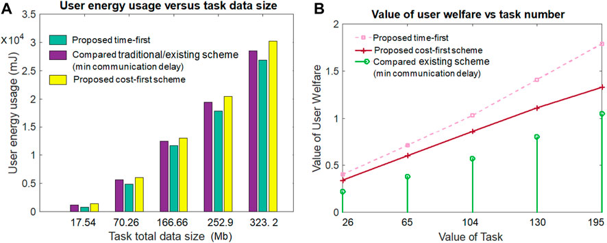
Figure 5. Energy usage and user welfare value.
Figure 5B notifies the results concerning the value of user welfare versus the task number for all three comparable schemes. Overall, the value of user welfare increases with the incremental value of task number. The user welfare value is determined by taking the sum of task implementation delay gain, energy usage gain, and service execution cost gain. The proposed time-first scheme produces a higher amount of user welfare value than both the proposed cost-first scheme and the compared scheme (min communication delay). The proposed cost-first scheme secures the second position and the compared scheme secures the third position in terms of the value of user welfare. The major reason behind this result is that the time-first scheme gives the highest task implementation delay gain, the highest energy usage gain, and the second highest service execution cost gain. Although the compared scheme (minimum communication delay) gives the highest service execution cost gain but the lowest task implementation delay gain and energy usage gain, the compared scheme gives the second highest task implementation delay gain, the second highest energy usage gain, and the lowest service execution cost gain. From Figure 5B, it is seen that when the task value is 65, the user welfare value for the proposed time-first, compared scheme (minimum communication delay), and proposed cost-first scheme are .71, .38, and .60, respectively.
Figure 6A hints that the service provider welfare increases with the large task total data size value in both the proposed and compared schemes. The service provider’s welfare is determined by taking the sum of revenue regarding the user’s task execution, computation delay, communication delay, and waiting delay. It can be noted from the figure that the proposed cost-first scheme offers a greater service provider welfare value than the others. The results depict that the compared scheme secures the third position and the proposed time-first scheme secures the second position in terms of service provider welfare. This is because the resource purchase and maintenance costs (e.g., remote cloud) are lower in the proposed cost-first scheme than the others. From Figure 6A, when the task data size value is 252.9 Mb, the service provider welfare value for the proposed time-first, compared scheme (minimum communication delay), and proposed cost-first scheme is 0.83, 0.30, and 1.09, respectively.
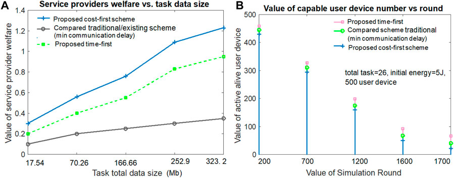
Figure 6. Service provider welfare and the alive user number.
Figure 6B examines the active and capable user device number versus the value of the simulation round for all three schemes. Figure 6B hints that the number of capable user devices reduces with the large simulation round value in all three schemes. The proposed time-first scheme gives the best results in terms of alive and capable user device numbers due to its lowest energy usage value during per-round task execution. The proposed cost-first scheme gives the lowest alive and capable user device number value due to its highest energy usage value during per-round task execution. The existing compared scheme (minimum communication delay) gives the second-best alive user device number due to its second-highest energy expense value per simulation round. From Figure 6B, when the task number is 26 and the simulation round is 1,700, the alive and capable user device values for the proposed time-first scheme, compared scheme (minimum communication delay), and proposed cost-first scheme are 66, 40, and 22, respectively.
The average survival or remaining user device energy value performance versus the simulation round for both the proposed and existing schemes is given in Figure 7B. It can be seen from Figure 7A that the average survival or leftover user device energy decreases with the incremental value of the simulation round in all three schemes. Hence, due to the lower amount of user device energy per task execution, the proposed time-first scheme offers the highest average survived energy value among others. It can also be noticed from Figure 7A that due to the second-best and worst energy consumption during task implementation, the existing compared scheme and the proposed cost-first scheme give the second-best and lowest average survival energy value. From Figure 7A, it can be noted that when the simulation round is 1,500 and task number is 26, the average survived energy value for the proposed time-first scheme, compared scheme (minimum communication delay), and proposed cost-first scheme is 1,190 mJ, 935 mJ, and 785 MJ, respectively.
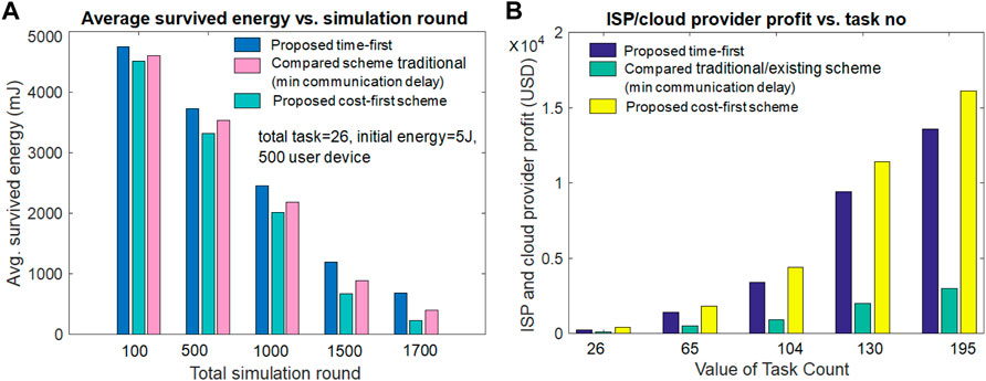
Figure 7. User survived energy and ISP/cloud service provider profit value.
Figure 7B discusses the ISP/cloud service providers’ profit result comparison by varying the task implementation value for both the proposed and compared schemes. Figure 7B depicts that the ISP/cloud provider profit increases with the incremental value of the task implementation number in all proposed and compared schemes. Due to lower resource costs, the proposed cost-first scheme provides the best ISP/cloud provider profit to others. The figure also shows that the proposed time-first scheme receives the second-best ISP/cloud provider profit due to its second-best task service execution cost. Although the compared scheme (minimum communication delay) gives the lowest ISP/cloud provider profit due to its highest task service execution cost and waiting delay for service. From Figure 7B, it can be pointed out that when the implemented task number is 195, the ISP/cloud provider profit value for the proposed time-first scheme, compared scheme (minimum communication delay), and proposed cost-first scheme is 13,600 USD, 3010 USD, and 16,100 USD, respectively.
5.1 Detailed comparison and performance gain analysis
Table 3 gives a comparative analysis (when the task number is 195) by taking three performance metrics results for the proposed time-first scheme, the proposed cost-first scheme, the traditional scheme with minimum communication delay-based resource selection (compared scheme 3), and the traditional scheme with high computational power-based resource selection (compared scheme 4). It can be seen from the table that the proposed time-first scheme offers the best possible average task implementation delay and users’ energy cost results. Although the proposed cost-first scheme shows the best possible user service execution cost results, the proposed cost-first scheme secures the third position in terms of average task implementation delay and users’ energy usage cost. The traditional scheme with minimum communication delay-based resource selection (compared scheme 3) secures the second position, whereas the traditional scheme with high computational power-based resource selection (compared scheme 4) achieves the fourth position among all compared schemes in terms of average task implementation delay and user service execution monetary cost results. The reason behind the supremacy of the proposed time-first scheme is that it selects the work node or resources based on the lowest predicted delay basis, which includes the associated computation delay, communication delay, and waiting delay. Although the proposed cost-first scheme selects the resource with the lowest cost for different task executions, the compared scheme 3 selects suitable resources by examining the lowest possible communication delay. The compared scheme 4 achieves worse results due to its random resource selection nature without examining different delays and costs for each task execution. The compared scheme selects work node based on high computational power. From Table 3, it is seen that when the implemented task number is 195, the average task implementation delay gain in the proposed time-first scheme over compared scheme 3 (minimum communication delay), proposed cost-first scheme, and compared scheme 4 (high computational power) are 25.27%, 52.83%, and 71.8%, respectively. Table 3 also reveals that when the implemented task number is 195, the user service execution cost gain in the proposed cost-first scheme over compared scheme 3 (minimum communication delay), proposed time-first scheme, and compared scheme 4 (high computational power) are 17.89%, 11.52%, and 24.06%, respectively. Table 3 also shows that when the implemented task number is 195, the user energy usage cost gain in the proposed time-first scheme over compared scheme 3(minimum communication delay), proposed cost-first scheme, and compared scheme 4 (high computational power) are 6.15%, 9.31%, and 12.14%, respectively.
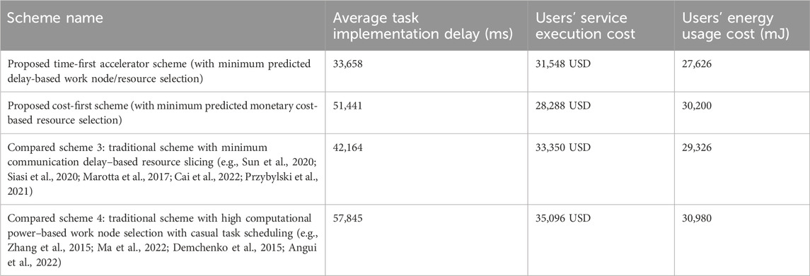
Table 3. Comparative performance analysis for task number = 195.
5.2 Computational complexity analysis
The computational complexity value of the proposed accelerator (both time-first and cost-first schemes) can be determined by O(y ∗ ϕrn + y ∗ ϕbr), where y is the total value of the 6G and non-6G application request amounts. ϕrn is the work node (physical and virtual resource) selection number per application request. ϕbr is the number of communication link resource selections per application execution. Thus, the computational complexity of the proposed accelerator (both time-first and cost-first schemes) is O(y ∗ ϕrn + y ∗ ϕbr) because the proposed accelerator scheme selects the best resources per application with minimum predicted task implementation delay cost and minimum monetary cost value. The best possible work node resources are selected by examining all available resource node statuses (i.e., O(y∗ϕrn)). The best possible communication link is selected for each application data transfer activity by examining all communication link statuses (i.e., O(y ∗ ϕbr)). Although the computational complexity of compared scheme 3 (minimum communication delay) or compared scheme 4 (maximum computational power) is O(y ∗ 1), for traditional scheme 3, the first nearby resource node is selected for each application execution. Similarly, for the traditional scheme 4, the work node with maximum power is selected for task execution. Thus, O(1) time is required for resource selection per application request in the traditional scheme 3 or 4. Hence, the proposed accelerator scheme requires more computational time complexity than the traditional scheme for best resource selection.
5.3 Feasibility of the practical implementation of the work
In Section 3.1, we discussed the network model, such as considerations and technical standards. We utilized currently available devices and IEEE standards. Thus, the proposed model is practically feasible. Algorithm 1 and Figure 2, as well as Section 3.2, describe how we implemented our work. Section 4 illustrates the mathematical model used for evaluation. In Section 5, we presented and discussed the simulation results, which included their advantages and disadvantages. Table 2 and Section 5 provide detailed information on the simulation parameters. The simulation results clearly show that the proposed system outperforms existing systems in terms of task implementation delay, energy consumption cost, service execution cost for users, quality guarantee ratio, throughput, and service provider welfare outcomes. Thus, the proposed system is both legally, technically, performance-wise, and economically feasible for practical implementation.
6 Conclusion
This work introduces a task execution time priority-first and monetary cost priority-first policy based on time slot scheduling, virtual and physical workers, and bandwidth resource assignment algorithm for different 6G and non-6G application execution over ZTNs. To speed up the 6G and non-6G application execution over the ZTN, the proposed network model integrates different technologies (e.g., SDN, NFV, blockchain, digital twin, and MEC), different types of communication links (e.g., wired and wireless links), and different user devices (e.g., IoT devices and robots). To examine the proposed scheme’s performance over a ZTN, this paper gives a performance analysis model that includes task implementation delay, energy cost, QoS guarantee ratio, and monetary cost metrics. It provides an accelerator-based task coordination and resource scheduling algorithm. The simulation results highlight that when the task number is 104, the average task implementation delay of the proposed time-first scheme, compared scheme 3 (minimum communication delay based), and the proposed cost-first resource selection policy are 12,455 ms, 20,202 ms, and 22,750 ms, respectively. For the data size value of 252.9 MB with 130 task number executions, the user’s energy usage value of the proposed time-first scheme, compared scheme 3 (minimum communication delay based), and the proposed cost-first resource selection policy are 18,329 mJ, 19,930 mJ, and 20,430 mJ, respectively. For the task number of 130, the service execution monetary cost value of the proposed time-first scheme, compared scheme 3 (minimum communication delay based), and proposed cost-first resource selection policies are 21,752 USD, 23,354 USD, and 14,990 USD, respectively. The evaluation results highlight that the proposed time-first scheme can offer maximum task implementation delay gain compared to other compared schemes. The simulation results also revealed that the proposed cost-first scheme can provide maximum service execution monetary cost gain compared to other compared schemes.
This work’s future research extensions include deep learning–based ZTN failure prediction, service request arrival prediction, quantum cryptography–based security enhancement, and machine learning–based congestion control for SDN- and NFV-enabled ZTN. The work’s limitation is that it did not investigate failure recovery, age-of-information-aware resource selection, or cost-effective VNF placement problems for ZTN-based 6G and non-6G application execution using DRL techniques. Furthermore, it did not look into blockchain and FL-based security and privacy checks for ZTN-based application execution. A semantic communication-aware resource-slicing framework can be developed in the future by taking into account more emerging next-generation application scenarios (e.g., industry 5.0), dynamic network scenarios, different attacks and trusted collaboration node selection, game theory–based resource sharing policy, and heterogeneous requirements satisfaction (e.g., load balancing and reliability guarantee) for ZTNs.
Abbreviation
SFC, service function chaining; MEC, mobile edge computing; SDN, software-defined networking; NFV, network function virtualization; VNF, virtual network function; THz, terahertz communication; ZTN, zero-touch networks; FeMBB, further enhanced mobile broadband; LDHMC, long-distance and high-mobility communications; umMTC, ultra-massive machine-type communication; URLLC, ultra-reliable low-latency communication; ELPC, extremely low-power communications; XR, extended reality; FW: firewall; DPI, digital packet inspection; AT, network address translation; IDS, intrusion detection; EV, electric vehicle; LB, load balancing.
Data availability statement
The original contributions presented in the study are included in the article/supplementary material; further inquiries can be directed to the corresponding author.
Author contributions
MC: writing—original draft and writing—review and editing.
Funding
The author declares that no financial support was received for the research, authorship, and/or publication of this article.
Conflict of interest
The author declares that the research was conducted in the absence of any commercial or financial relationships that could be construed as a potential conflict of interest.
Publisher’s note
All claims expressed in this article are solely those of the authors and do not necessarily represent those of their affiliated organizations, or those of the publisher, the editors, and the reviewers. Any product that may be evaluated in this article, or claim that may be made by its manufacturer, is not guaranteed or endorsed by the publisher.
References
Abbas, K., Afaq, M., Ahmed Khan, T., Rafiq, A., and Song, W. C. (2020). Slicing the core network and radio access network domains through intent-based networking for 5G networks. Electronics 9 (10), 1710–1715. id 1710. doi:10.3390/electronics9101710
Adhikari, M., Munusamy, A., Kumar, N., and Srirama, S. (2022). Cybertwin-driven resource provisioning for IoE applications at 6G-enabled edge networks. IEEE Trans. Industrial Inf. 18 (7), 4850–4858. doi:10.1109/tii.2021.3096672
Alsabah, M., Naser, M. A., Mahmmod, B. M., Abdulhussain, S. H., Eissa, M. R., Al-Baidhani, A., et al. (2021). 6G wireless communications networks: a comprehensive survey. IEEE Access 9, 148191–148243. doi:10.1109/access.2021.3124812
Alwis, C. D., Kalla, A., Pham, Q. V., Kumar, P., Dev, K., Hwang, W. J., et al. (2021). Survey on 6G Frontiers: trends, applications, requirements, technologies and future research. IEEE Open J. Commun. Soc. 2, 836–886. doi:10.1109/ojcoms.2021.3071496
Amreen, Srinivas, P., Rao, N. T., Bhattacharyya, D., and Kim, H. j. (2017). Performance evaluation in cloud computing model using queuing models. Int. J. Grid Distributed Comput. 10 (3), 15–24. doi:10.14257/ijgdc.2017.10.3.02
Angui, B., Corbel, R., Rodriguez, V. Q., and Stephan, E. (2022). “Towards 6G zero touch networks: the case of automated Cloud-RAN deployments,” in IEEE 19th annual consumer communications & networking conference (CCNC), 1–6.
Ashraf, I., Zikria, Y. B., Garg, S., Park, Y., Kaddoum, G., and Singh, S. (2022). Zero touch networks to realize virtualization: opportunities, challenges, and future prospects. IEEE Netw. 36 (6), 251–259. doi:10.1109/mnet.001.2200029
Basu, D., Kal, S., Ghosh, U., and Datta, R. (2022). SoftChain: dynamic resource management and SFC provisioning for 5G using machine learning. IEEE Globecom Work. (GC Wkshps), 280–285. doi:10.1109/gcwkshps56602.2022.10008691
Boškov, I., Yetgin, H., Vucnik, M., Fortuna, C., and Mohorcic, M. (2020). Time-to-Provision evaluation of IoT devices using automated zero-touch provisioning. IEEE Glob. Commun. Conf., 1–7. doi:10.1109/globecom42002.2020.9348119
Brik, B., and Ksentini, A. (2020). “On predicting service-oriented network slices performances in 5G: a federated learning approach,” in IEEE 45th Conference on Local Computer Networks (LCN), Sydney, NSW, 164–171. doi:10.1109/LCN48667.2020.9314849
Cai, Y., Llorca, J., Tulino, A. M., and Molisch, A. F. (2022). “Compute- and data-intensive networks: the key to the Metaverse,” in 1st international conference on 6G networking (6GNet), 1–8.
Cao, H., Du, J., Zhao, H., Luo, D. X., Kumar, N., Yang, L., et al. (2021). Resource-ability assisted service function chain embedding and scheduling for 6G networks with virtualization. IEEE Trans. Veh. Technol. 70 (4), 3846–3859. doi:10.1109/tvt.2021.3065967
Chen, J., Cheng, X., and Zhang, H. (2022). A lightweight SFC embedding framework in SDN/NFV-enabled wireless network based on reinforcement learning. IEEE Syst. J. 16 (3), 3817–3828. doi:10.1109/jsyst.2021.3111972
Chen, J., Deng, Q., and Yang, X. (2023). Non-cooperative game algorithms for computation offloading in mobile edge computing environments. J. Parallel Distributed Comput. 172 (xx), 18–31. doi:10.1016/j.jpdc.2022.10.004
Chen, J., Li, K., Deng, Q., Li, K., and Yu, P. S. (2019). Distributed deep learning model for intelligent video surveillance systems with edge computing. IEEE Trans. Industrial Inf., 1–8. doi:10.1109/tii.2019.2909473
Chen, W., Wang, Z., Zhang, H., Yin, X., and Shi, X. (2021). “Cost-efficient dynamic service function chain embedding in edge clouds,” in 17th International Conference on Network and Service Management (CNSM), Izmir, Turkey, 310–318. doi:10.23919/CNSM52442.2021.9615590
Chergui, H., Blanco, L., Garrido, L. A., Ramantas, K., Kuklinski, S., Ksentini, A., et al. (2021). Zero-touch AI-driven distributed management for energy-efficient 6G massive network slicing. IEEE Netw. 35 (6), 43–49. doi:10.1109/mnet.111.2100322
Chowdhury, M. (2022). An energy harvesting, blockchain, and QoS-aware intelligent healthcare task coordination policy for IoT-assisted networks. Int. J. Embed. Syst. 15 (4), 313–325. doi:10.1504/ijes.2022.10050472
Collet, A., Banchs, A., and Fiore, M. (2022). “LossLeaP: learning to predict for intent-based networking,” in IEEE INFOCOM 2022 - IEEE Conference on Computer Communications, London, United Kingdom, 2138–2147. doi:10.1109/INFOCOM48880.2022.9796918
Coronado, E., Behravesh, R., Subramanya, T., Fernandez-Fernandez, A., Siddiqui, M. S., Costa-Perez, X., et al. (2022). Zero touch management: a survey of network automation solutions for 5G and 6G networks. IEEE Commun. Surv. Tutorials 24 (4), 2535–2578. doi:10.1109/comst.2022.3212586
Coronado, E., Behravesh, R., Subramanya, T., Fernandez-Fernandez, A., Siddiqui, M. S., Costa-Perez, X., et al. (2022). Zero touch management: a survey of network automation solutions for 5G and 6G networks. IEEE Commun. Surv. Tutorials 24 (4), 2535–2578. doi:10.1109/comst.2022.3212586
Dalgkitsis, A., Mekikis, P. -V., Antonopoulos, A., Kormentzas, G., and Verikoukis, C. (2020). “Dynamic resource aware VNF placement with deep reinforcement learning for 5G networks,” in GLOBECOM 2020 - 2020 IEEE Global Communications Conference, Taipei, Taiwan, 1–6. doi:10.1109/GLOBECOM42002.2020.9322512
Demchenko, Y., Filiposka, S., Tuminauskas, R., Mishev, A., Baumann, K., Regvart, D., et al. (2015). “Enabling automated network services provisioning for cloud based applications using zero touch provisioning,” in IEEE/ACM 8th international conference on utility and cloud computing (UCC), Limassol, Cyprus, 458–464. doi:10.1109/UCC.2015.82
Drolia, U., Guo, K., Tan, J., Gandhi, R., and Narasimhan, P. (2017). Cachier: edge-caching for recognition applications. IEEE ICDCS, 276–286. doi:10.1109/icdcs.2017.94
El Houda, Z. A., Brik, B., and Khoukhi, L. (2022). Ensemble learning for intrusion detection in SDN-based zero touch smart grid systems. IEEE 47th Conf. Local Comput. Netw. (LCN) 2022, 149–156. doi:10.1109/lcn53696.2022.9843645
Fathalla, A., Li, K., and Salah, A. (2022). Best-KFF: a multi-objective preemptive resource allocation policy for cloud computing systems. Clust. Comput. 25 (1), 321–336. doi:10.1007/s10586-021-03407-z
Feng, L., Zi, Y., Li, W., Zhou, F., Yu, P., and Kadoch, M. (2020). Dynamic resource allocation with RAN slicing and scheduling for uRLLC and eMBB hybrid services. IEEE Access 8, 34538–34551. doi:10.1109/access.2020.2974812
Grasso, C., Raftopoulos, R., and Schembra, G. (2021). Smart zero-touch management of UAV-based edge network. IEEE Trans. Netw. Serv. Manag. 19 (4), 4350–4368. doi:10.1109/tnsm.2022.3160858
Gu, Y., Hu, Y., Ding, Y., Lu, J., and Xie, J. (2019). Elastic virtual network function orchestration policy based on workload prediction. IEEE Access 7, 96868–96878. doi:10.1109/access.2019.2929260
Hantouti, H., Benamar, N., and Taleb, T. (2020). Service function chaining in 5G & beyond networks: challenges and open research issues. IEEE Netw. 34 (4), 320–327. doi:10.1109/mnet.001.1900554
Hermosilla, A., Zarca, A. M., Bernabe, J. B., Ortiz, J., and Skarmeta, A. (2020). Security orchestration and enforcement in NFV/SDN-Aware UAV deployments. IEEE Access 8, 131779–131795. doi:10.1109/access.2020.3010209
Hu, J., Li, K., Liu, C., Chen, J., and Li, K. (2021). Coalition formation for deadline-constrained resource procurement in cloud computing. J. Parallel Distributed Comput. 149 (xx), 1–12. doi:10.1016/j.jpdc.2020.10.004
Huang, L., Pan, Y., Yang, J., Shen, D., Chen, S., and Huang, L. (2023) A hybrid meta-heuristic algorithm with fuzzy clustering method for IoT smart electronic applications. Int. J. Embed. Syst. 16:(01), 57–66. doi:10.1504/ijes.2023.10059681
Jalalitabar, M., Wang, Y., and Cao, X. (2019). “Branching-aware service function placement and routing in network function virtualization,” in IEEE conference on network function virtualization and software defined networks (NFV-sdn), Dallas, TX, 1–6. doi:10.1109/NFV-SDN47374.2019.9039981
Ksentini, A. (2021). Tutorial: zero touch management and orchestration of network slices in 5G and beyond networks. IEEE Int. Conf. Commun. 2021, 1–6.
Lin, R., He, L., Luo, S., and Zukerman, M. (2023). Energy-aware service function chaining embedding in NFV networks. IEEE Trans. Serv. Comput. 16 (2), 1158–1171. doi:10.1109/tsc.2022.3162328
Lin, R., Luo, S., and Zukerman, M. (2022). Service function chaining embedding in hybrid optical-electronic networks. J. Light. Technol. 40 (15), 4922–4933. doi:10.1109/jlt.2022.3176473
Lin, S.-C., Lin, C.-H., and Chen, W.-C. (2022). Zero-touch network on industrial IoT: an end-to-end machine learning approach. IEEE Netw., 1–8. Submitted for publication in the journal.
Liyanage, M., Pham, Q. V., Dev, K., Bhattacharya, S., Maddikunta, P. K. R., Gadekallu, T. R., et al. (2022). A survey on Zero touch network and Service Management (ZSM) for 5G and beyond networks. J. Netw. Comput. Appl. 203 (103362), 103362–103427. doi:10.1016/j.jnca.2022.103362
Luque-Schempp, F., Panizo, L., Gallardo, M. d. M., Merino, P., and Rivas, J. (2022). Toward zero touch configuration of 5G non-public networks for time sensitive networking. IEEE Netw. 36 (2), 50–56. doi:10.1109/mnet.006.2100442
Ma, J., Guo, Y., Fang, C., and Zhang, Q. (2022). Digital twin-based zero-touch management for IoT. Electronics 11 (4104), 4104. doi:10.3390/electronics11244104
Marotta, A., Zola, E., D'Andreagiovanni, F., and Kassler, A. (2017). A fast robust optimization-based heuristic for the deployment of green virtual network functions. J. Netw. Comput. Appl. 95, 42–53. doi:10.1016/j.jnca.2017.07.014
Martini, B., Gharbaoui, M., and Castoldi, P. (2022). Intent-based zero-touch service chaining layer for software-defined edge cloud networks. Comput. Netw. 212 (109034), 109034–109115. doi:10.1016/j.comnet.2022.109034
Mohamad, A., and Hassanein, H. S. (2022). Prediction-based SFC placement with VNF sharing at the edge. IEEE 47th LCN, 26–33. doi:10.1109/lcn53696.2022.9843704
Mohammadpour, A., Lombardo, C., Bolla, R., Bruschi, R., Davoli, F., and Ivaldi, L. (2022). “A zero-touch as-a-Service active monitoring framework for virtualized network environments,” in IEEE 8th international Conference on network softwarization (NetSoft), Milan, Italy, 103–108. doi:10.1109/NetSoft54395.2022.9844069
Multiple Authors, (2022a). Number connected-iot devices Available at: https://iot-analytics.com/number-connected-iot-devices/,” acessed 01 december 2022.
Multiple Authors (2022b). Zero touch networks opportunities challenges and potential. Available at: https://www.comsoc.org/publications/magazines/ieee-network/cfp/zero-touch-networks-opportunities-challenges-and-potential.
Nibouchaet, R., Saad, S. B., Ksentini, A., and Challal, Y. (2023). Zero-touch security management for mMTC network slices: DDoS attack detection and mitigation. IEEE Internet Things J. 10 (9), 7800–7812. doi:10.1109/jiot.2022.3230875
Okwuibe, J., Haavisto, J., Kovacevic, I., Harjula, E., Ahmad, I., Islam, J., et al. (2021). SDN-enabled resource orchestration for industrial IoT in collaborative edge-cloud networks. IEEE Access 9, 115839–115854. doi:10.1109/access.2021.3105944
Pei, J., Hong, P., Xue, K., Li, D., Wei, D. S. L., and Wu, F. (2020). Two-phase virtual network function selection and chaining algorithm based on deep learning in SDN/NFV-enabled networks. IEEE J. Sel. Areas Commun. 38 (6), 1102–1117. doi:10.1109/jsac.2020.2986592
Przybylski, B., Zuk, P., and Rzadca, K. (2021). “Data-driven scheduling in serverless computing to reduce response time,” in 2021 IEEE/ACM 21st International Symposium on Cluster, Cloud and Internet Computing (CCGrid), Melbourne, Australia, 206–216.
Red Hat (2024). What is NFV? Available at: https://www.redhat.com/en/topics/virtualization/what-is-nfv.
Rico-Palomo, J. J., Galeano-Brajones, J., Cortes-Polo, D., Valenzuela-Valdes, J. F., and Carmona-Murillo, J. (2022). Chained orchestrator algorithm for RAN-slicing resource management: a contribution to ultra-reliable 6G communications. IEEE Access 10, 113662–113677. doi:10.1109/access.2022.3218061
Roy, S., Chergui, H., Sanabria-Russo, L., and Verikoukis, C. (2022). A cloud native SLA-driven stochastic federated learning policy for 6G zero-touch network slicing. IEEE Int. Conf. Commun. 2022, 4269–4274. doi:10.1109/icc45855.2022.9838376
Saha, D., Shojaee, M., Baddeley, M., and Haque, I. (2020). “An energy-aware SDN/NFV architecture for the internet of things,” in IFIP Networking Conference (Networking), Paris, France 2020, 604–608.
Saha, M., Panda, S. K., and Panigrahi, S. (2023). A modified Brown and Gibson model for cloud service selection. Int. J. Comput. Sci. Eng. 26 (4), 430–444. doi:10.1504/ijcse.2023.132150
Salameh, A. I., and El Tarhuni, M. (2022). From 5G to 6G—challenges, technologies, and applications. Future Internet 14 (117), 117–135. doi:10.3390/fi14040117
Sebrechts, M., Volckaert, B., De Turck, F., Yang, K., and Al-Naday, M. (2022). Fog native architecture: intent-based workflows to take cloud native toward the edge. IEEE Commun. Mag. 60 (8), 44–50. doi:10.1109/mcom.003.2101075
Shaghaghi, A., Mokari, N., Javan, M. R., Behdadfar, M., and Jorswieck, E. A. (2021). Proactive and AoI-aware failure recovery for stateful NFV-enabled zero-touch 6G networks: model-free DRL approach. IEEE TNSM, 1–14.
Siasi, N., Jasim, M., Aldalbahi, A., and Ghani, N. (2020). Delay-aware SFC provisioning in hybrid fog-cloud computing architectures. IEEE Access 8, 167383–167396. doi:10.1109/access.2020.3021354
Song, F., Li, J., Ma, C., Zhang, Y., Shi, L., and Jayakody, D. N. K. (2020). Dynamic virtual resource allocation for 5G and beyond network slicing. IEEE Open J. Veh. Technol. 1, 215–226. doi:10.1109/ojvt.2020.2990072
Sousa, N. F. S. d., and Rothenberg, C. E. (2021). “CLARA: closed loop-based zero-touch network management framework,” in IEEE conference on network function virtualization and software defined networks (NFV-sdn), Heraklion, Greece, 110–115. doi:10.1109/NFV-SDN53031.2021.9665048
Suh, K., Kim, S., Ahn, Y., Kim, S., Ju, H., and Shim, B. (2022). Deep reinforcement learning-based network slicing for beyond 5G. IEEE Access 10, 7384–7395. doi:10.1109/access.2022.3141789
Sun, G., Xu, Z., Yu, H., Chen, X., Chang, V., and Vasilakos, A. V. (2020). Low-latency and resource-efficient service function chaining orchestration in network function virtualization. IEEE IoT J. 7 (7), 5760–5772. doi:10.1109/jiot.2019.2937110
Tamim, I., Jammal, M., Hawilo, H., and Shami, A. (2020). Introducing virtual security functions into latency-aware placement for NFV applications. IEEE ICC, Dublin, Irel., 1–7. doi:10.1109/icc40277.2020.9149288
Tang, J., Duan, Y., Zhou, Y., and Jin, J. (2021). Distributed slice selection-based computation offloading for intelligent vehicular networks. IEEE Open J. Veh. Technol. 2, 261–271. doi:10.1109/ojvt.2021.3087355
Theodorou, V., Lekidis, A., Bozios, T., Meth, K., Fernández-Fernández, A., Tavlor, J., et al. (2021). “Blockchain-based zero touch service assurance in cross-domain network slicing,” in Joint European Conference on Networks and Communications and 6G Summit (EuCNC/6G Summit), Porto, Portugal, 395–400. doi:10.1109/EuCNC/6GSummit51104.2021.9482602
Thiruvasagam, P. K., Chakraborty, A., and Murthy, C. S. R. (2021). Resilient and latency-aware orchestration of network slices using multi-connectivity in MEC-enabled 5G networks. IEEE Trans. Netw. Serv. Manag. 18 (3), 2502–2514. doi:10.1109/tnsm.2021.3091053
Tianran, D., Tian, G., Wei, J., and Liu, S. (2023). Blockchain-based collaborative intrusion detection scheme. Int. J. Embed. Syst. 26 (4), 418–429. doi:10.1504/ijcse.2023.132147
Tseng, H.-W., Yang, T. T., and Hsu, F. T. (2021). An MEC-based VNF placement and scheduling scheme for AR application topology. IEEE WCNC, 1–6. doi:10.1109/wcnc49053.2021.9417126
VMware (2024). What is software-defined networking? Available at: https://www.vmware.com/topics/glossary/content/.
Wang, P., Li, K., Xiao, B., and Li, K. (2022). Multiobjective optimization for joint task offloading, power assignment, and resource allocation in mobile edge computing. IEEE IoT J. 9 (14), 11737–11748. doi:10.1109/jiot.2021.3132080
Wang, Y., and Farooq, J. (2022). Zero touch coordinated UAV network formation for 360 degree views of a moving ground target in remote VR applications. IEEE Mil. Commun. Conf. (MILCOM) 2022, 950–955.
Wang, Y., Huang, C. K., Shen, S. H., and Chiu, G. M. (2021). Adaptive placement and routing for service function chains with service deadlines. IEEE Trans. Netw. Serv. Manag. 18 (3), 3021–3036. doi:10.1109/tnsm.2021.3086977
Wei, S., Zhou, J., and Chen, S. (2022). Delay-aware multipath parallel SFC orchestration. IEEE Access 10, 120035–120055. doi:10.1109/access.2022.3221744
Xu, Y.-H., Hua, M., Zhou, W., and Yu, G. (2022). Resource allocation for cellular zero-touch deterministic industrial M2M networks: a reinforcement learning-based scheme. IEEE Sensors Lett. 6 (8), 1–4. doi:10.1109/lsens.2022.3194141
Yoshino, M., Astawa, G., Trinh, T., Suzuki, H., Koswara, M., and Nguyen, B. (2021). Zero-touch multi-service provisioning with pluggable module-type OLT in access network virtualization testbed. GLOBECOM 2020 - 2020 IEEE Glob. Commun. Conf. 2020, 148800–148809. doi:10.1109/access.2021.3110249
Zahoor, S., Ahmad, I., Othman, M. T. B., Mamoon, A., Rehman, A. U., Shafiq, M., et al. (2022). Comprehensive analysis of network slicing for the developing commercial needs and networking challenges. MDPI Sensors 22 (17), 6623–6721. doi:10.3390/s22176623
Zahoor, S., Ahmad, I., Ur Rehman, A., Tag Eldin, E., A. Ghamry, N., and Shafiq, M. (2023). Performance evaluation of virtualization methodologies to facilitate NFV deployment. Comput. Mater. Continua 75 (1), 311–329. doi:10.32604/cmc.2023.035960
Zhang, D., Chen, X., Huang, Q., Hong, X., Wu, C., Zhou, H., et al. (2019). P4SC: a high performance and flexible framework for service function chain. IEEE Access 7, 160982–160997. doi:10.1109/access.2019.2950446
Zhang, W., Wen, Y., and Wu, D. O. (2015). Collaborative task execution in mobile cloud computing under a stochastic wireless channel. IEEE Trans. Wirel. Commun. 14 (1), 81–93. doi:10.1109/twc.2014.2331051
Zhong, X., Wang, Y., and Qiu, X. (2019). “Cost-aware service function chaining with reliability guarantees in NFV-enabled inter-DC network,” in IFIP/IEEE Symposium on Integrated Network and Service Management (IM), Arlington, VA 2019, 304–311.
Keywords: network slicing, zero-touch network, resource slicing, mobile edge computing, service function chaining, network function virtualization, blockchain, SDN
Citation: Chowdhury M (2024) Accelerator: an intent-based intelligent resource-slicing scheme for SFC-based 6G application execution over SDN- and NFV-empowered zero-touch network. Front. Comms. Net 5:1385656. doi: 10.3389/frcmn.2024.1385656
Received: 13 February 2024; Accepted: 10 May 2024;
Published: 04 July 2024.
Edited by:
Junaid Shuja, University of Technology Petronas, MalaysiaReviewed by:
Ehzaz Mustafa, COMSATS University Islamabad, PakistanAdeel Iqbal, Yeungnam University, Republic of Korea
Copyright © 2024 Chowdhury. This is an open-access article distributed under the terms of the Creative Commons Attribution License (CC BY). The use, distribution or reproduction in other forums is permitted, provided the original author(s) and the copyright owner(s) are credited and that the original publication in this journal is cited, in accordance with accepted academic practice. No use, distribution or reproduction is permitted which does not comply with these terms.
*Correspondence: Mahfuzulhoq Chowdhury, bWFoZnV6dWxob3EuY3NlMDVAZ21haWwuY29t