 Santiago A. Lopez
 Daniel Gomez
 Albert R. Ortiz
 Sandra Villamizar
94% of researchers rate our articles as excellent or good
Learn more about the work of our research integrity team to safeguard the quality of each article we publish.
Find out more
ORIGINAL RESEARCH article
Front. Built Environ., 04 February 2025
Sec. Computational Methods in Structural Engineering
Volume 10 - 2024 | https://doi.org/10.3389/fbuil.2024.1524027
This article is part of the Research TopicNext-Generation Methods for Sustainable Structural Design and MonitoringView all articles
The human body, composed of interconnected subsystems with complex dynamic behavior, is often oversimplified or neglected by structural designers and building codes. Human-induced loads, whether passive (e.g., standing, sitting) or active (e.g., walking, dancing, jumping), considerably impact the dynamic response of structures such as grandstands, slender slabs, and pedestrian bridges, highlighting the necessity for their consideration in design. This study introduces three closed-loop control models to represent the human-structure interaction (HSI) effect: a Proportional Integral (PI) controller, the Pole Placement control algorithm (PP), and the Linear Quadratic Regulator with an Observer (LQR + L). While well-established in robotics and automation engineering, these control algorithms represent a novel and transformative approach when applied to HSI. They offer an intuitive and effective framework for modeling the dynamic feedback mechanisms inherent in HSI. The model parameters are obtained using global optimization and curve fitting methods, followed by experimental validation on a test structure. The results of this study indicate that feedback controllers accurately predict the experimental structural response for different subjects. These findings highlight the importance of incorporating HSI effects into structural design, promising the design of safer and more comfortable structures in human-occupied environments.
In recent years, the use of novel materials and design methods has allowed a growing trend toward the construction of lightweight, slender, and aesthetically appealing structures, including thin staircases, long-span bridges, composite slabs, and grandstands (Jones et al., 2011; Chen et al., 2018; Feng et al., 2019; Huang et al., 2020). These flexible structures are typically characterized by low natural frequencies and damping, making them susceptible to vibration serviceability issues as human-induced vibrations (Gomez et al., 2021). Despite their importance, the dynamic effect of passive occupants is often neglected in structural analysis, leading to unexpected structural behavior (Sachse et al., 2004; Busca et al., 2014). Several studies have reported significant changes in the dynamic characteristics of structures due to the presence of people (Reynolds and Pavic, 2004; Wei et al., 2019). One of the most well-known examples of unexpected behavior due to human activities on structures is the Millennium Bridge in England, which experienced excessive vibrations on its opening day (Dallard et al., 2001; Strogatz et al., 2005). This case sparked great concern about Human-Structure Interaction (HSI) and the importance of accurately predicting the response of slender structures.
Most structural designers, codes, and guidelines simplify the effects of human activities on structures by considering them as a static uniformly distributed load per unit area with a reference value (Eurocode 1, 2006; ASCE, 2013). Despite numerous studies and tests attempting to establish realistic values for live loads, significant differences in suggested values persist. This variability can lead to either overestimation or underestimation of the impact of human activities, potentially causing unexpected vibrations in structural elements. Serviceability limits are typically set to ensure that a structure remains functional and comfortable for its intended use. While these vibrations may not directly damage the structure, they can cause discomfort for occupants, disrupt sensitive equipment, and interfere with the structure’s normal operation (Zhu et al., 2020). Therefore, guidelines and design codes set a lower limit for the equivalent static live load and the expected natural frequency to enhance structural vibration serviceability (Eurocode 5, 2006; NBC, 2015). This approach aims to prevent occupant discomfort and minimize the risk of resonant responses due to human activities. However, by neglecting Human-Structure Interaction (HSI), current codes and guidelines often lead to inaccurate predictions of a structure’s dynamic response, typically underestimating the impact of occupants (Matsumoto and Griffin, 2003; Subashi et al., 2006). To address this, the dynamic effects of stationary individuals should be more thoroughly investigated and integrated into the structural analysis and design of elements like thin slabs and grandstands (Gomez et al., 2018).
Considering the different dynamic characteristics of the human-structure system compared to the empty structure, it is crucial to treat both humans and the structure as dynamic systems (Reynolds and Pavic, 2004; Busca et al., 2014). Therefore, researchers have approached the standing human as an equivalent mass-spring-damper (MSD) system, considering from a single degree of freedom (SDOF) to higher-order systems, instead of treating the human as an added mass (Wei and Griffin, 1998; Matsumoto and Griffin, 2003; Zhang, 2013; Hashim et al., 2020). However, models based on lumped systems often fail to depict standing humans. This is attributed to the complexity of the human body, encompassing intricate subsystems that respond variably to different vibration levels, ultimately introducing considerable uncertainty into the models (Ortiz and Caicedo, 2019; Calonge et al., 2023). Biomechanical studies have attempted to understand the human response to vibration by investigating factors such as the ability to generate feedback to maintain balance and the apparent mass and stiffness, which can vary according to different parameters (Subashi et al., 2006; Subashi et al., 2008; Bierbaum et al., 2011). Chagdes et al. (2013) analyzed the stability of a standing human on an unstable platform as a coupled system with nonlinear muscle stiffness, significant sway, and a time delay in the neuromuscular feedback. Consequently, accurate prediction of HSI effects requires precise models that capture this complex behavior.
This study develops and evaluates three feedback control-based models to represent the effects of HSI. Section 2 defines the HSI, establishing the theoretical framework for the analysis. Section 3 outlines the experimental program designed to evaluate the HSI. Section 4 describes the proposed feedback models, detailing how the Proportional Integral (PI) controller, the Pole Placement (PP) controller, and the Linear Quadratic Regulator with an Observer (LQR + L) are applied to represent the influence of a standing human. Section 5 outlines the fitting process and compares the similarity between the results obtained from the proposed models and the experimental data. The document concludes with a summary of the key findings, underscoring the development of control models capable of representing HSI.
Researchers have experimentally demonstrated that a human in passive and active conditions contributes not only additional mass but also affects the frequency and damping properties of a structure (Brownjohn, 2001; Pedersen, 2008; Ortiz et al., 2012; Gomez et al., 2021). Through free vibration and forced-vibration tests, they compared the responses of structures loaded with sandbags, equivalent in weight to a human, to those loaded with humans in a passive condition. The results revealed differences depending on the participant’s weight and posture. These findings emphasize the relevance of developing strategies that accurately represent this behavior.
The HSI is defined as the mutual dynamic effect of the human and the structure on each other (Ahmadi et al., 2019). HSI encompasses two parts: 1) the effect of the human body on the structural dynamic properties and 2) the influence of structural vibrations on human behavior. These two components interact in a feedback loop (Lin et al., 2021), resulting in dynamic changes in the human-structure system, such as changes in natural frequencies and modal damping due to human presence (Brownjohn, 1999; Busca et al., 2014). Like a feedback control system, which employs measured responses to optimize system performance and achieve desired outcomes, humans exhibit a similar capability when interacting with structures. HSI is not confined to active scenarios like dancing or running; it also occurs when individuals are stationary, such as sitting or standing. Even in passive conditions, the human body influences the structure by interacting with it through factors like body sway, posture adjustments, and changes in mass distribution. Consider the scenario where a structure experiences excessive vibrations, a standing human detects these vibrations and instinctively responds to maintain balance while reducing the vibrations. This interaction directly affects the structural response, making human behavior a natural feedback control system that instinctively adjusts to maintain balance and mitigate vibrations.
Control systems engineering encompasses the modeling of diverse physical systems and uses these models to synthesize control strategies that provide the desired performance characteristics of system. A control system integrates multiple components, forming an interconnected system configuration (Ogata and Brewer, 2010). Typically, control systems are depicted using block diagrams that visually represent the relationship between each system component, and this technique allows each system element to be modeled separately. Similarly, the HSI examines the relationship between a structure with readily representable behavior and the human part whose behavior depends on several parameters associated with high uncertainties. Partitioning the coupled HSI system enhances the understanding of subsystem dynamics, making control theory a straightforward and intuitive approach to describing the HSI effect.
Figure 1 illustrates a closed-loop control system, where an impact hammer hits the structure (known as the plant) and generates a disturbance signal
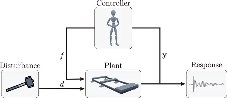
Figure 1. Feedback block diagram, representing the free vibration tests.
The structure employed for testing is a cantilever steel structure consisting of
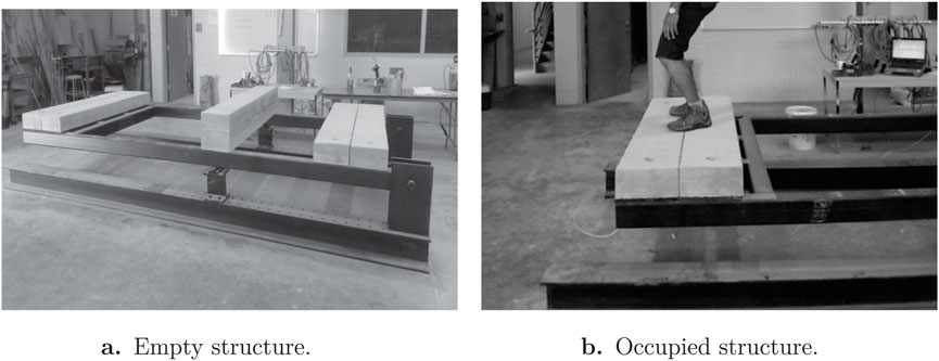
Figure 2. Experimental configuration for conducting HSI tests. Adapted from Ortiz (2016). (A) Empty structure. (B) Occupied structure.
The experimental data used in this study were obtained from impact hammer tests conducted by Ortiz (2016). For this experiment, the structure was equipped with two accelerometers positioned in the vertical and horizontal directions at the midpoint of the cantilever. Impact forces were applied to concrete blocks within less than 0.1 m from the edge. Data were sampled at 1,652 Hz and filtered using a low-pass filter with a cutoff frequency of 20 Hz to eliminate higher frequencies. Two distinct sets of tests were performed. The first set of tests focused on characterizing the dynamic properties of the empty structure (Figure 2A). The second set involved testing the structure with a person standing on it, thereby capturing the HSI and the overall response of the entire human-structure system (Figure 2B). During the test program, nine subjects participated, each with their corresponding properties detailed in Table 1. Three tests were conducted for each subject to ensure repeatability; however, only one record was used for the analysis. The participants gave informed consent, with approval from the University of South Carolina Institutional Review Board.
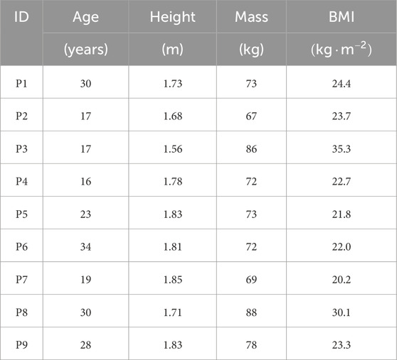
Table 1. Properties of subjects involved in tests.
Figures 3, 4 show a reduction in natural frequencies across all participants. Notably, the frequency response in the vertical direction exhibited a more significant decrease in magnitude, suggesting a stronger control action in this orientation. Additionally, the responses imply that disturbances in the vertical direction induce vibrations in both vertical and horizontal axes. In line with previous studies on HSI (Brownjohn, 2001; Busca et al., 2014; Wei et al., 2019), the experimental frequency responses from the occupied structure indicate that human presence can lower natural frequencies and increase damping within the coupled system.
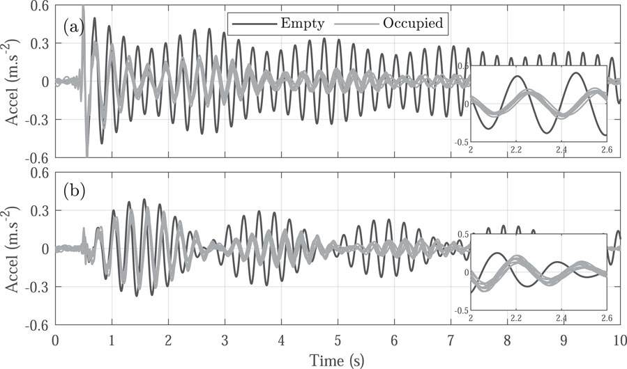
Figure 3. Experimental time response for the empty (black line) and occupied (gray lines) structure. (A) Acceleration in the vertical direction. (B) Acceleration in the horizontal direction.
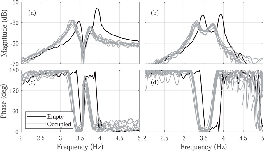
Figure 4. Experimental transfer functions for the empty (black line) and occupied (gray lines) structure. (A, C) show the magnitude and phase in the vertical direction, respectively. (B, D) show the magnitude and phase in the horizontal direction.
This section introduces the proposed models to represent the HSI depicted by Figure 1. The framework allows for independent modeling of each subsystem, enabling a more comprehensive understanding of how each component of the coupled human-structure system contributes to the overall response. Using a state-space approach reduces the complexity of the mathematical expressions in this Multiple-Input Multiple-Output (MIMO). In the occupied structure, the impact hammer and human control actions act as inputs, while the acceleration responses in both vertical and horizontal directions are the outputs. The framework captures the bidirectional interactions between the structure and the human, where each affects the other. These interactions alter the dynamic characteristics of the combined subsystems. The mathematical formulation for each component is detailed below.
Based on the sensor placement at the middle-end of the cantilever (Figure 5) and the observed frequency response, the structure is modeled as a two DOFs linear system (Equation 1), accounting for both vertical
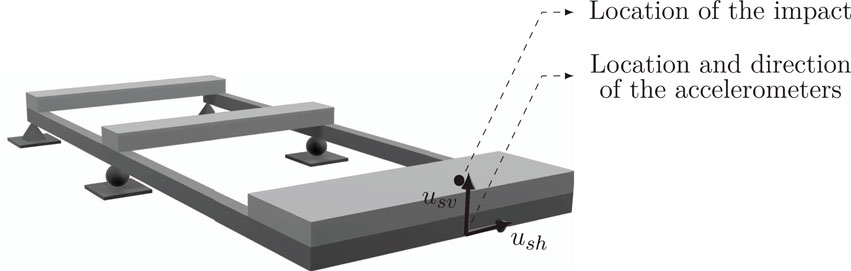
Figure 5. Schematic representation of the experimental structure and the setup.
Referring to the structural displacement defined as
where
The structure subsystem incorporates both the hammer force and the human control force. However, when the structure is empty, there is no
where
and the defined states
where
The human control action consists of three key components: sensory organization, central motor planning, and motor execution, which work together to select appropriate responses and adjust the system in a closed-loop manner (Ortiz and Caicedo, 2015). First, sensory organization occurs through mechanisms such as the visual, vestibular, and proprioceptive systems, which gather information about the environment. Second, the brain processes this sensory input (controlling) and generates commands to maintain the desired state, such as equilibrium. Third, motor execution (acting) occurs through the coordinated interaction of muscles and the skeletal system to apply the necessary forces (Fransson et al., 1998). This process mirrors the fundamental elements of a control system, allowing human behavior to be modeled using control theory techniques, which provides deeper insights into its dynamics. Viewing humans through this control-system perspective offers a novel approach to understanding how they interact with structures in response to vibrations.
Typically, controller design implies several design performance criteria, such as control effort, overshoot, and state error. These criteria help ensure the system achieves the desired performance while minimizing energy consumption and improving response accuracy. However, in this study, the controller parameters were adjusted by comparing the experimental data with the modeled responses to minimize the error between them. This approach ensures that the modeled system closely replicates the observed behavior.
The Proportional Integral (PI) controller is a variation of the widely used Proportional Integral Derivative (PID) controller, both of which are extensively applied in industrial settings. The PID’s versatility proves advantageous, as it can be applied to different dynamic systems, even in cases where the mathematical model of the plant is not entirely known (Ogata and Brewer, 2010; Dorf, 2017). Specifically, the PI controller is defined by Equation 6, and the control action is computed from the estimated vertical acceleration response of the structure, as depicted by Equation 7; Figure 6, where
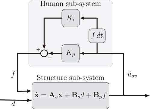
Figure 6. Block diagram of the PI controller representing the HSI.
The PID controller was also evaluated. However, there was no significant difference with the fit obtained with the PI, showing that including the derivative term does not contribute significantly to the response in this case. The PI with only two terms can represent the changes observed in the response both in the frequency and time domains. Hence, for its simplicity, it is preferred over the PID. It is also noteworthy that this controller has been previously used to represent the HSI through a closed-loop control system, yielding similar values for a structure with a single dominant frequency (Ortiz and Caicedo, 2015).
The Pole Placement (PP) algorithm, or pole assignment, involves selecting desired pole locations in the complex plane corresponding to specific dynamic characteristics, such as stability and responsiveness. By strategically positioning these poles, the control system can achieve the desired transient and steady-state performance. The desired closed-loop pole locations are determined experimentally from the transfer function, rather than through predefined design criteria. This method assumes that all state variables are both measurable and available for feedback, and that the system is fully state-controllable.
The states refer to a set of variables that capture the essential characteristics of a dynamic system at any given time. These variables, such as position and velocity, are sufficient to predict the system’s future behavior when the current inputs are known. In this model, the states not only represent physical quantities but also serve as the foundation for computing the control action. Thus, in contrast to the PI model where the control action is derived solely from system outputs, the PP algorithm directly generates the control force using a set of defined states
The desired locations of the closed-loop poles are determined by the experimental transfer function. By leveraging state feedback, the algorithm places the closed-loop poles in specific locations on the complex plane, ensuring the system behaves as required. This process is achieved through an appropriate state feedback gain matrix,
The whole human-structure system through this approach is depicted in Figure 7.
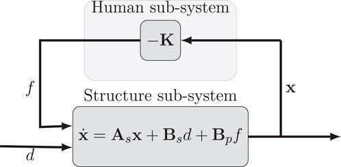
Figure 7. Block diagram of PP method representing the HSI.
By substituting Equation 9 into Equation 4, the closed-loop system equation (Equation 10) is obtained. This equation highlights the changes in the system matrix corresponding to the closed-loop system and, consequently, its eigenvalues. This observation exhibits how the controller can effectively capture changes in the structural dynamics induced by human interaction without introducing complexity to the closed-loop system. This ensures that the closed-loop system maintains the same number of poles and zeros as the empty structure.
The third model representing the subject includes two essential components: a Linear Quadratic Regulator (LQR), which calculates the control action, and a Luenberger observer (L), which estimates the system’s states to enable accurate control. The LQR provides a key advantage over the Pole Placement (PP) method by systematically determining the state feedback matrix through optimization. Specifically, the gain matrix K in the LQR is obtained by minimizing a performance index,
where matrices Q and R assign weights to the significance of the state variables x and the control action
The Luenberger observer enhances the accuracy of closed-loop state estimations by using the difference between measured and estimated responses to provide a precise assessment of the system’s actual states. This approach combines sensed data with knowledge of the control system to estimate the states
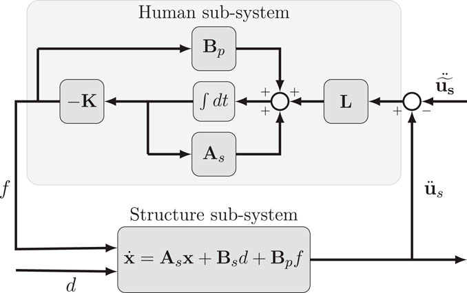
Figure 8. Block diagram of LQR + L control.
The state estimation is computed, as Equation 12 shows. To address potential inaccuracies in the system matrices
The parameters of the proposed models are fitted using a global optimization algorithm in MATLAB. This process aims to minimize the Normalized Mean Square Error (NMSE) between the model response,
The cost function
where the NMSE of the vertical and horizontal acceleration time responses are denoted as
As outlined in Equations 4, 5, the proposed state-space model for the empty structure accounts for two distinct vibration modes. The first mode has an identified frequency of 3.47 Hz and a damping ratio of 0.32%, while the second mode exhibits a frequency of 3.93 Hz and a damping ratio of 0.74%. This model framework allows for a detailed analysis of the human influence over both modes. With an average fit of 96.84%, this representation indicates a close match between the experimental and modeled time and frequency responses of the empty structure, as illustrated in Figures 9, 10, respectively. This confirms that the structural formulation based on dynamic properties effectively captures the behavior in both time and frequency domains.
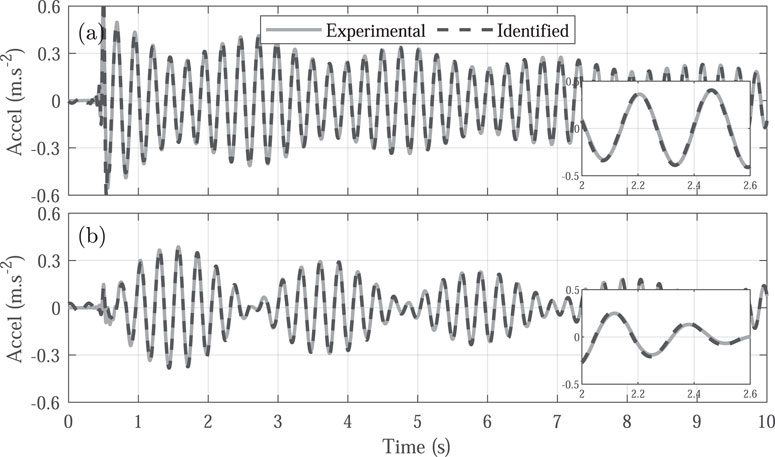
Figure 9. Experimental time response (solid line) and state-space model prediction response (dashed line) for the empty structure. (A) Acceleration in the vertical direction. (B) Acceleration in the horizontal direction.

Figure 10. Experimental frequency response (solid line) and state-space model prediction response (dashed line) for the empty structure. (A, C) show the magnitude and phase in the vertical direction, respectively. (B, D) show the magnitude and phase in the horizontal direction, respectively.
Once the structure has been characterized, the interaction between the subject and the structure is represented using feedback control algorithms. For the occupied structure, the parameters for each human model are estimated using data from six individual subjects. The estimation process involved determining the parameters that best fit the experimental responses for each subject (Table 2). Subsequently, the model derived from the average parameter (Avg.) values is subjected to validation using the data from the remaining three subjects. All human-structure coupled models considered in this study successfully capture the decreased natural frequencies and the additional damping observed in the occupied system. This is achieved by adjusting the closed-loop poles to more stable positions, accurately reflecting the influence of HSI.
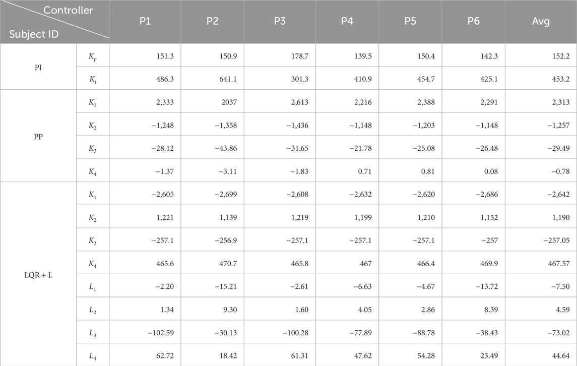
Table 2. Summary of the controller parameter values obtained during the fitting process.
The first model considered is the PI controller, with the optimization process yielding proportional
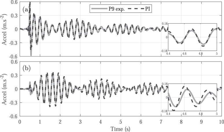
Figure 11. Experimental time response (solid line) and PI controller prediction response (dashed line) for the occupied structure. (A) Acceleration in the vertical direction. (B) Acceleration in the horizontal direction.
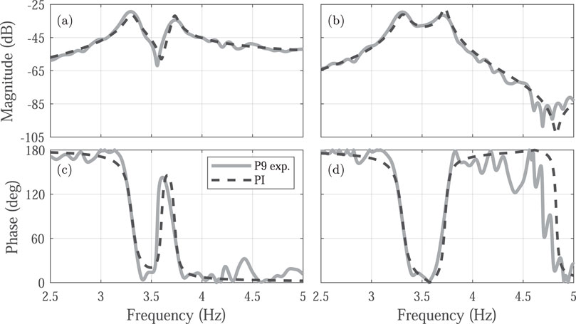
Figure 12. Experimental frequency response (solid line) and PI controller prediction response (dashed line) for the occupied structure. (A, C) show the magnitude and phase in the vertical direction, respectively. (B, D) show the magnitude and phase in the horizontal direction, respectively.
The PP method enables for the precise positioning of the system’s closed-loop poles at specific locations in the s-plane. This location is significant because the poles correspond to the system’s eigenvalues, determining its dynamic response. By adjusting the feedback gain matrix K, based on the estimated states of the structural model, the method provides precise control over the system’s behavior without introducing additional frequencies. Although tuning this method is more complex than the PI controller, PP method effectively captures essential system changes, such as increased damping and reduced natural frequencies, without increasing the overall complexity of the closed-loop system (Figures 13, 14).
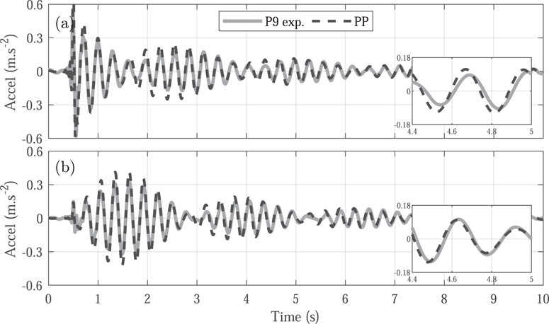
Figure 13. Experimental time response (solid line) and PP controller prediction response (dashed line) for the occupied structure. (A) Acceleration in the vertical direction. (B) Acceleration in the horizontal direction.

Figure 14. Experimental frequency response (solid line) and PP controller prediction response (dashed line) for the occupied structure. (A, C) show the magnitude and phase in the vertical direction, respectively. (B, D) show the magnitude and phase in the horizontal direction, respectively.
The LQR + L controller calculates the control action by incorporating the difference between the measured and estimated responses, rather than depending solely on estimated values. As shown in Figure 15, this approach results in a more accurate agreement with the time-domain response, demonstrating the model’s effectiveness in capturing the system’s behavior. Additionally, the closed-loop response successfully captures the variations observed in the experimental frequency response (Figure 16), making the LQR + L controller a more robust solution for managing uncertainties and accounting for unmodeled dynamics.
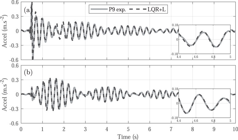
Figure 15. Experimental time response (solid line) and LQR + L controller prediction response (dashed line) for the occupied structure. (A) Acceleration in the vertical direction. (B) Acceleration in the horizontal direction.
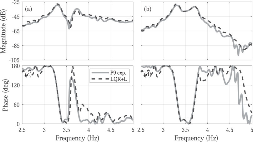
Figure 16. Experimental frequency response (solid line) and LQR + L controller prediction response (dashed line) for the occupied structure. (A, C) show the magnitude and phase in the vertical direction, respectively. (B, D) show the magnitude and phase in the horizontal direction, respectively.
Each modeling approach for HSI introduces a varying level of complexity to the overall human-structure system. The PI controller provides a simple representation of HSI, requiring only two additional parameters. In contrast, the Pole Placement approach does not rely on the system’s acceleration response to compute the control action; instead, it uses the calculated states. This assumes that the human perceives (or estimates) the velocity and displacement as states and generates a control action based on these states without adding complexity to the closed-loop system. The LQR + L controller refines this by using the difference between measured and estimated states to compute the control action, allowing it to account for unmodeled dynamics and improve accuracy, particularly in capturing uncertainties in the system’s behavior.
While these control models do not directly correspond to a physical representation of human behavior, they offer a simpler and more efficient alternative to traditional mass-spring-damper (MSD) models. By requiring fewer parameters, they result in a less complex closed-loop system, thereby reducing computational demand for calculating the system response. Moreover, these models, particularly the LQR + L controller, demonstrate strong accuracy in predicting the response of the occupied system in both time and frequency domains, as illustrated in Figure 17. Each controller achieves different errors relative to experimental data, even in validation cases where information not used in the adjustment process is involved.
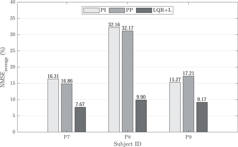
Figure 17. Obtained average NMSE error relative to experimental data.
Although these control models do not directly correspond to a physical representation of human behavior, they provide a simpler and more efficient alternative to traditional mass-spring-damper (MSD) models. By requiring fewer parameters, they reduce the complexity of the closed-loop system and minimize computational demands for calculating the system response. Notably, these models, particularly the LQR + L controller, exhibit high accuracy in predicting the response of the occupied system across both time and frequency domains, as shown in Figure 17. Each controller achieves different error levels relative to the experimental data, even in validation scenarios involving information not used during the fitting process.
This study develops three feedback control models to represent Human-Structure Interaction (HSI) using experimental data from free vibration tests on a cantilever steel frame occupied by a standing human. The results reveal consistent changes in the structural response, including reductions in natural frequencies and increases in damping, with a more pronounced impact observed in the vertical direction. This suggests that standing subjects exert greater control along this axis, which aligns with the direction of the external load. Each control algorithm introduces varying levels of complexity, with more advanced controllers generally achieving lower errors compared to experimental data, even in atypical cases such as subjects with higher Body Mass Index (BMI). These models offer greater flexibility in adjusting closed-loop poles, while ensuring that no frequencies beyond those observed in the experimental data are introduced. Additionally, their simplicity enables faster analysis, making them highly practical for scenarios demanding computational efficiency. Among the tested controllers, the Linear Quadratic Regulator with an Observer (LQR + L) demonstrates superior performance, achieving the lowest Normalized Mean Square Error (NMSE) across all validation subjects, with NMSE values of 7.67%, 9.90%, and 9.17% for subjects P7, P8, and P9, respectively. These findings underscore the importance of integrating HSI effects into structural design through advanced feedback control models, offering a deeper understanding of human influence on structural dynamics. Future research should focus on refining these models and exploring their broader applicability across diverse structural systems.
The data analyzed in this study is subject to the following licenses/restrictions: The dataset is available upon request. Requests to access these datasets should be directed to YWxiZXJ0Lm9ydGl6QGNvcnJlb3VuaXZhbGxlLmVkdS5jbw==.
The studies involving human participants were reviewed and approved by the University of South Carolina Institutional Review Board. The participants provided their written informed consent to participate in this study.
SL: Conceptualization, Methodology, Writing–review and editing, Formal Analysis, Investigation, Writing–original draft. DG: Conceptualization, Data curation, Formal Analysis, Investigation, Methodology, Writing–original draft, Writing–review and editing. AO: Conceptualization, Formal Analysis, Investigation, Methodology, Supervision, Writing–original draft, Writing–review and editing. SV: Methodology, Supervision, Writing–review and editing.
The author(s) declare that financial support was received for the research, authorship, and/or publication of this article. This work was financially supported by the Universidad del Valle, Colombia (Grant No. 21125: Feedback control theory for modeling human-structure interaction).
The authors declare that the research was conducted in the absence of any commercial or financial relationships that could be construed as a potential conflict of interest.
The author(s) declare that no Generative AI was used in the creation of this manuscript.
All claims expressed in this article are solely those of the authors and do not necessarily represent those of their affiliated organizations, or those of the publisher, the editors and the reviewers. Any product that may be evaluated in this article, or claim that may be made by its manufacturer, is not guaranteed or endorsed by the publisher.
Ahmadi, E., Caprani, C., Živanović, S., and Heidarpour, A. (2019). Assessment of human-structure interaction on a lively lightweight GFRP footbridge. Eng. Struct. 199, 109687. doi:10.1016/j.engstruct.2019.109687
ASCE (2013). “SEI 7-10,” in Minimum design loads for buildings and other structures (American Society of Civil Engineers). doi:10.1061/9780784412916
Bierbaum, S., Peper, A., Karamanidis, K., and Arampatzis, A. (2011). Adaptive feedback potential in dynamic stability during disturbed walking in the elderly. J. Biomechanics 44, 1921–1926. doi:10.1016/j.jbiomech.2011.04.027
Brownjohn, J. (1999). “Energy dissipation in one-way slabs with human participation,” in Asia pacific vibration conference, 155–160.
Brownjohn, J. M. (2001). Energy dissipation from vibrating floor slabs due to human-structure interaction. Shock Vib. 8, 315–323. doi:10.1155/2001/454139
Busca, G., Cappellini, A., Manzoni, S., Tarabini, M., and Vanali, M. (2014). Quantification of changes in modal parameters due to the presence of passive people on a slender structure. J. Sound Vib. 333, 5641–5652. doi:10.1016/j.jsv.2014.06.003
Calonge, J. D., Gomez, D., and Ortiz, A. R. (2023). Robust feedback models with structured uncertainties for human-structure interaction. Mech. Syst. Signal Process. 202, 110681. doi:10.1016/j.ymssp.2023.110681
Chagdes, J. R., Rietdyk, S., Jeffrey, M. H., Howard, N. Z., and Raman, A. (2013). Dynamic stability of a human standing on a balance board. J. Biomechanics 46, 2593–2602. doi:10.1016/j.jbiomech.2013.08.012
Chen, S., Zhang, R., and Zhang, J. (2018). Human-induced vibration of steel-concrete composite floors. Proc. Institution Civ. Eng. Struct. Build. 171, 50–63. doi:10.1680/jstbu.16.00179
Dallard, P., Fitzpatrick, T., Flint, A., Low, A., Smith, R. R., Willford, M., et al. (2001). London millennium bridge: pedestrian-induced lateral vibration. J. Bridge Eng. 6, 412–417. doi:10.1061/(ASCE)1084-0702(2001)6:6(412)
Feng, P., Wang, Z., Jin, F., and Zhu, S. (2019). Vibration serviceability assessment of pedestrian bridges based on comfort level. J. Perform. Constr. Facil. 33, 04019046. doi:10.1061/(ASCE)CF.1943-5509.0001316
Fransson, P.-A., Magnusson, M., and Johansson, R. (1998). Analysis of adaptation in anteroposterior dynamics of human postural control. Gait and posture 7, 64–74. doi:10.1016/S0966-6362(97)00030-1
Gomez, D., Dyke, S. J., and Rietdyk, S. (2018). Experimental verification of a substructure-based model to describe pedestrian–bridge interaction. J. Bridge Eng. 23, 4018013. doi:10.1061/(ASCE)BE.1943-5592.0001204
Gomez, D., Rietdyk, S., and Dyke, S. J. (2021). Spatio-temporal assessment of gait kinematics in vertical pedestrian-structure interaction. Struct. (Elsevier) 31, 1199–1206. doi:10.1016/j.istruc.2021.02.024
Hashim, R., Ji, T., Mandal, P., Zhang, Q., and Zhou, D. (2020). Human-structure interaction experiments to determine the dynamic properties of the standing human body in vertical vibration. Structures 26, 934–946. doi:10.1016/j.istruc.2020.04.040
Huang, H., Gao, Y., and Chang, W. S. (2020). Human-induced vibration of cross-laminated timber (CLT) floor under different boundary conditions. Eng. Struct. 204, 110016. doi:10.1016/j.engstruct.2019.110016
Jones, C. A., Reynolds, P., and Pavic, A. (2011). Vibration serviceability of stadia structures subjected to dynamic crowd loads: a literature review. J. Sound Vib. 330, 1531–1566. doi:10.1016/j.jsv.2010.10.032
Lin, B., Zhang, Q., Fan, F., and Shen, S. (2021). Reproducing vertical human walking loads on rigid level surfaces with a damped bipedal inverted pendulum. Structures 33, 1789–1801. doi:10.1016/j.istruc.2021.05.048
Matsumoto, Y., and Griffin, M. J. (2003). Mathematical models for the apparent masses of standing subjects exposed to vertical whole-body vibration. J. Sound Vib. 260, 431–451. doi:10.1016/S0022-460X(02)00941-0
Ogata, K., and Brewer, J. W. (2010). Modern control engineering. J. Dyn. Syst. Meas. Control 93, 63. doi:10.1115/1.3426465
Ortiz, A. R. (2016). Modeling human-structure interaction using a controller system. Ph.D. thesis. Columbia, South Carolina: University of South Carolina.
Ortiz, A. R., and Caicedo, J. M. (2015). Comparing closed loop control models and mass-spring-damper models for human structure interaction problems. Dyn. Civ. Struct. 2, 67–74. doi:10.1007/978-3-319-15248-6_7
Ortiz, A. R., and Caicedo, J. M. (2019). Modeling the effects of a human standing on a structure using a closed loop–control system. J. Eng. Mech. 145. doi:10.1061/(ASCE)EM.1943-7889.0001583
Ortiz, A. R., Gomez, D., and Thomson, P. (2012). Efectos de la interacción humano-estructura en las propiedades dinámicas de una tribuna. Ing. Compet. . 14, 63–73. doi:10.25100/iyc.v14i1.2639
Pedersen, L. (2008). “An aspect of dynamic human-structure interaction,” in Conference proceedings: imac-xxvi: a conference and exposition on structural dynamics (Society for Experimental Mechanics), 1–9.
Reynolds, P., and Pavic, A. (2004). Changes of modal properties of a stadium structure occupied by a crowd. Proc. IMAC 2004, 1–10.
Sachse, R., Pavic, A., and Reynolds, P. (2004). Parametric study of modal properties of damped two-degree-of-freedom crowd–structure dynamic systems. J. Sound Vib. 274, 461–480. doi:10.1016/j.jsv.2003.08.052
Strogatz, S. H., Abrams, D. M., McRobie, A., Eckhardt, B., and Ott, E. (2005). Theoretical mechanics: crowd synchrony on the millennium bridge. Nature 438, 43–44. doi:10.1038/43843a
Subashi, G. H., Matsumoto, Y., and Griffin, M. J. (2008). Modelling resonances of the standing body exposed to vertical whole-body vibration: effects of posture. J. Sound Vib. 317, 400–418. doi:10.1016/j.jsv.2008.03.019
Subashi, G. H. M. J., Matsumoto, Y., and Griffin, M. J. (2006). Apparent mass and cross-axis apparent mass of standing subjects during exposure to vertical whole-body vibration. J. Sound Vib. 293, 78–95. doi:10.1016/j.jsv.2005.09.007
Wei, L., and Griffin, M. (1998). Mathematical models for the apparent mass of the seated human body exposed to vertical vibration. J. Sound Vib. 212, 855–874. doi:10.1006/jsvi.1997.1473
Wei, X., Živanović, S., Russell, J., and Mottershead, J. E. (2019). Subsystem identification in structures with a human occupant based on composite frequency response functions. Mech. Syst. Signal Process. 120, 290–307. doi:10.1016/j.ymssp.2018.09.018
Zhang, Q. (2013). Models of a standing human body in structural vibration. Manchester, UK: University of Manchester. Ph.D. thesis.
Keywords: human-structure interaction, standing human, vibration serviceability, feedback control, full-scale testing, dynamics analysis, sub-structuring method, state-space modeling
Citation: Lopez SA, Gomez D, Ortiz AR and Villamizar S (2025) Integrating feedback control for improved human-structure interaction analysis. Front. Built Environ. 10:1524027. doi: 10.3389/fbuil.2024.1524027
Received: 06 November 2024; Accepted: 30 December 2024;
Published: 04 February 2025.
Edited by:
Muayad Habashneh, Széchenyi István University, HungaryReviewed by:
Sanjukta Chakraborty, Indian Institute of Technology Palakkad, IndiaCopyright © 2025 Lopez, Gomez, Ortiz and Villamizar. This is an open-access article distributed under the terms of the Creative Commons Attribution License (CC BY). The use, distribution or reproduction in other forums is permitted, provided the original author(s) and the copyright owner(s) are credited and that the original publication in this journal is cited, in accordance with accepted academic practice. No use, distribution or reproduction is permitted which does not comply with these terms.
*Correspondence: Daniel Gomez, ZGFuaWVsLmdvbWV6QGNvcnJlb3VuaXZhbGxlLmVkdS5jbw==
Disclaimer: All claims expressed in this article are solely those of the authors and do not necessarily represent those of their affiliated organizations, or those of the publisher, the editors and the reviewers. Any product that may be evaluated in this article or claim that may be made by its manufacturer is not guaranteed or endorsed by the publisher.
Research integrity at Frontiers
Learn more about the work of our research integrity team to safeguard the quality of each article we publish.