- 1Department of Architecture and Building Science, Graduate School of Engineering, Tohoku University, Sendai, Japan
- 2Earthquake Engineering Laboratory, International Research Institute of Disaster Science, Tohoku University, Sendai, Japan
A tuned viscous mass damper (TVMD) and a tuned inerter damper (TID) have been proposed as devices that can achieve weight reduction by replacing the mass element of a structural dynamic vibration absorber (DVA) with an inerter. In the TID, the damping element is arranged in parallel with the spring, making its device topology the same as conventional dynamic vibration absorbers. In contrast, in the TVMD the damping element is arranged in parallel with the inerter. This parallel mechanism of inerter and damping element can be realized in a single device, and the member of the building that supports the device can be used as the spring element, making the TVMD highly practical. In fact, TVMDs with a mass effect equivalent to thousands of tons have been commercialized and applied to high-rise buildings in Japan. This paper aims to clarify the effects of the choice of objective functions and damping element arrangement on the seismic response control effectiveness of inerter-based structural DVAs, providing guidelines for structural engineers in selecting suitable devices to achieve desired control effects. The method of investigation considers a model that encompasses both TVMD and TID configurations and formulates a multi-objective optimization problem to simultaneously minimize the displacement amplification factor and floor response acceleration amplification factor. The results of the multi-objective optimization reveal that the TVMD is optimal when the focus is on controlling displacement response, while the TID is optimal when prioritizing the control of floor response acceleration. It was found that the floor response acceleration amplification factor of a structure containing TVMD could be significantly improved by slightly compromising the displacement response amplification factor, leading to the recommendation of adopting the TVMD configuration as an inerter-based structural DVA.
1 Introduction
Owing to simplicity and independence from external power supplies, passive control technologies are widely applied in practice to suppress undesirable vibrations, including viscous and viscoelastic dampers (Housner et al., 1997; De Domenico et al., 2019; Licari et al., 2015; Kim et al., 2006; Mazza and Labernarda, 2020). However, these conventional dampers generate insufficient control forces when subjected to long-period ground motions, and thus their seismic performance is compromised (Keivan et al., 2017; Luo et al., 2019; Luo and Ikago, 2021). Inerter-based vibration control systems (IVCSs) that can enhance energy dissipation at certain frequencies have been proven to be more effective in addressing this challenge (Ikago et al., 2012a; Lazar et al., 2014; Zhang et al., 2020; Ji et al., 2020; Wang et al., 2024).
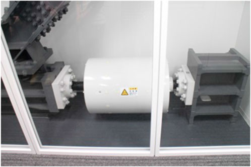
An inerter produces force proportional to the relative acceleration between its two terminals, serving as a crucial element in mechanical networks (Smith, 2002; Makris and Moghimi, 2022). The physical realization methods of an inerter include the use of hydraulics (Nakamura et al., 1988; Domenico et al., 2019; Wang et al., 2011), ball-screw mechanisms (Arakaki et al., 1999; Hwang et al., 2007; Papageorgiou et al., 2009; Watanabe et al., 2012; Kida et al., 2012; Nakamura et al., 2014), rack-and-pinion systems (Smith, 2002; Papageorgiou et al., 2009; Saitoh, 2012; Makris and Kampas, 2016), and living hinges (John and Wagg, 2019). Owing to the attractive characteristics of mass amplification effects and frequency-dependent negative stiffness yielded by inerters, various types of inerter-based vibration control systems (IVCSs) have been proposed (Ma et al., 2021). Ikago et al. (2012a) developed a tuned viscous mass damper (TVMD) consisting of a supporting spring connected in series with a parallel arrangement of an inerter and dashpot, and they verified its control effectiveness through numerical analysis and shaking table tests. Watanabe et al. (2012) and Kida et al. (2012) introduced a force-restriction mechanism to the TVMD to limit excessive control forces caused by the large mass amplification effects and extreme excitations. TVMD devices have been put to practical use in high-rise buildings in Japan (Sugimura et al., 2012; Ogino and Sumiyama, 2014; Ishii et al., 2014). Figure 1 is a photograph of a rotary inerter-damper having 6,400 tons of inertance incorporated into a telecommunications building in Sendai, Japan.
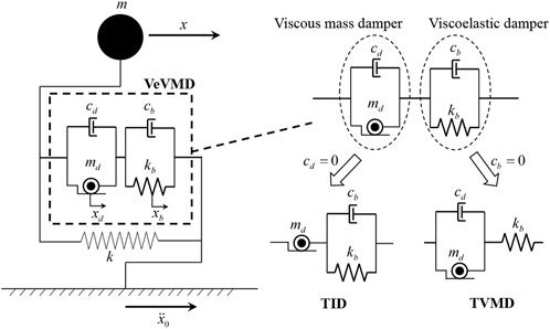
Zhao et al. (2016) proposed a viscoelastically supported viscous mass damper (VeVMD) by connecting a viscoelastic element to a parallel inerter-damper device in series and investigated its application to base-isolated structures. Unlike TVMD and VeVMD, the configuration of the tuned inerter damper (TID) proposed by Lazar et al. (2014) is similar to that of a traditional tuned mass damper (TMD). Another way of using an inerter to improve the performance of a TMD is the tuned mass damper inerter (TMDI) proposed by Marian and Giaralis (2014). Further different configurations of IVCSs have been investigated by Hu and Chen (2015) and Pan and Zhang (2018).
Analytical solutions for the
Although single-objective optimum design using relative displacement or floor response acceleration as an objective function is simple and thus convenient for the design of IVCS systems, more than two response values that are in a trade-off relationship are considered simultaneously in structural design practice. Pan et al. (2018) examined a multi-objective optimum design problem (MODP) to minimize response and cost for a TVMD-variant damper by using an
This study intends to identify the benefits and drawbacks of the IVCSs in controlling displacement and absolute acceleration through illustrative multi-objective designs of the VeVMD with a device topology that encompasses those of the two major inerter-based structural DVAs studied in the literature—the TVMD and TID. The peak displacement and peak absolute acceleration amplification factors employed as objective functions are highly associated with damage to structural and nonstructural components, which are highlighted as major issues for the seismic resilience of high-rise buildings (Ji et al., 2020). The rest of this paper is organized as follows. In Section 2, an analytical model of a SDOF structure containing a VeVMD is presented, and two transfer functions are introduced as objective functions for a multi-objective optimum design problem. Section 3 shows how the multi-objective optimum design of VeVMD converges to TVMD and TID device topologies when the focus is on displacement and absolute acceleration control, respectively. In Section 4, an analytical example using a ten-story shear building equipped with TVMD and TID subjected to strong ground motions, demonstrating that the
2 Amplification factors
2.1 Single-degree-of-freedom structural model and equations of motion
The analytical model of a SDOF structure equipped with a VeVMD is presented in Figure 2. The mass and stiffness of the primary SDOF structure are
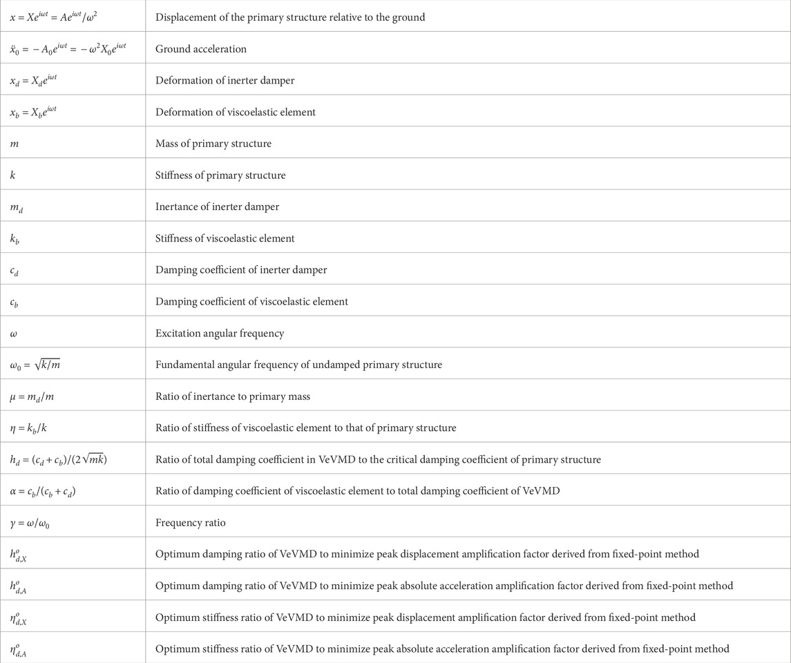
Table 1 summarizes the notations used in this paper.
2.2 Transfer functions
Here we consider a harmonic ground excitation
Accordingly, Equation 1 can be rewritten as
where
In this study, we examined two transfer functions,
Substituting Equations 3 and 4 into Equation 5 obtains
Introducing the nondimensional parameters are expressed in Equation 8.
Equations 6 and 7 can be rewritten as
Note that
3 Single- and multi-objective
3.1 Fixed-point method for single-objective
The dimensionless displacement transfer function shown in Equation 9 can be rewritten as Equation 11.
where
The denominator of the right-hand side of Equation 12 indicates that
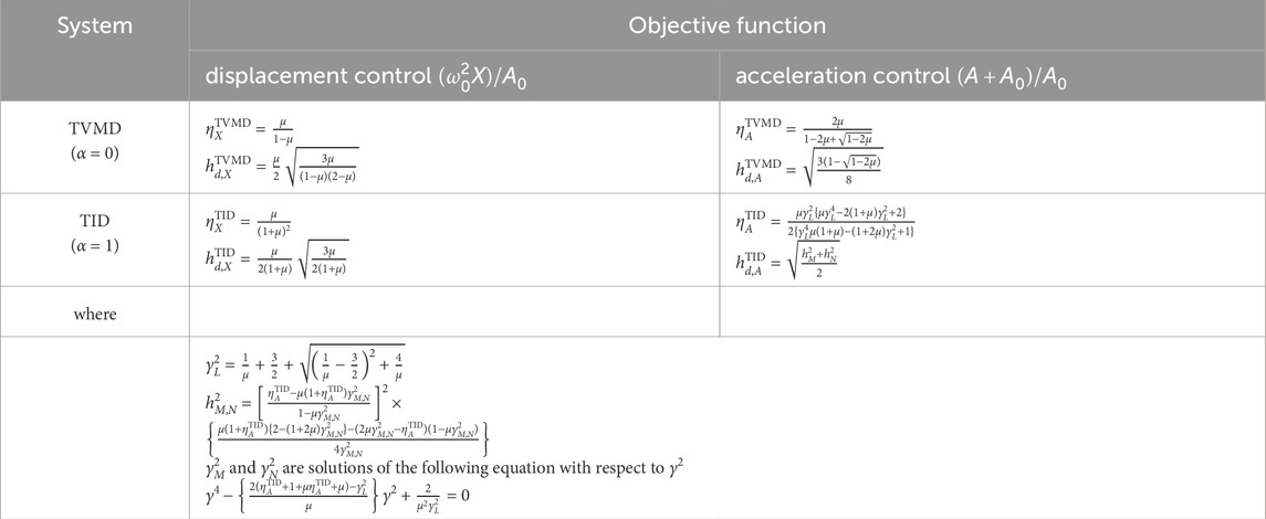
Table 2.
3.2 Definition of non-inferiority
Since we consider a multi-objective minimization problem in this study, the following definitions apply (Fonseca and Fleming, 1993) (Figure 3).
3.2.1 Inferiority
A vector
3.2.2 Superiority
A vector
3.2.3 Non-inferiority
Vectors
3.3 Multi-objective optimum design problems
Here, Equation 14 defines the infinity norms of the transfer functions as follows:
The multi-objective optimum design problem is formulated as shown in Equation 15. [MODP]
The solution of this problem is not a single design but a set of non-inferior designs, referred to as the “Pareto-optimal set”.
Here, the total damping coefficient in the VeVMD is preset such that
[Scalarized optimum design problem]
where
3.4 Pareto-optimal set
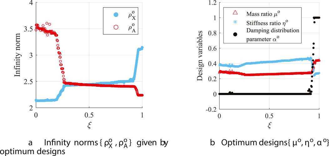
The Pareto-optimal set obtained by solving Equation 16 are functions of
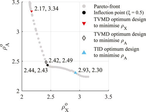
Thus, as shown in Figure 5A, the optimum designs are classified into TVMD, VeVMD, and TID configurations when
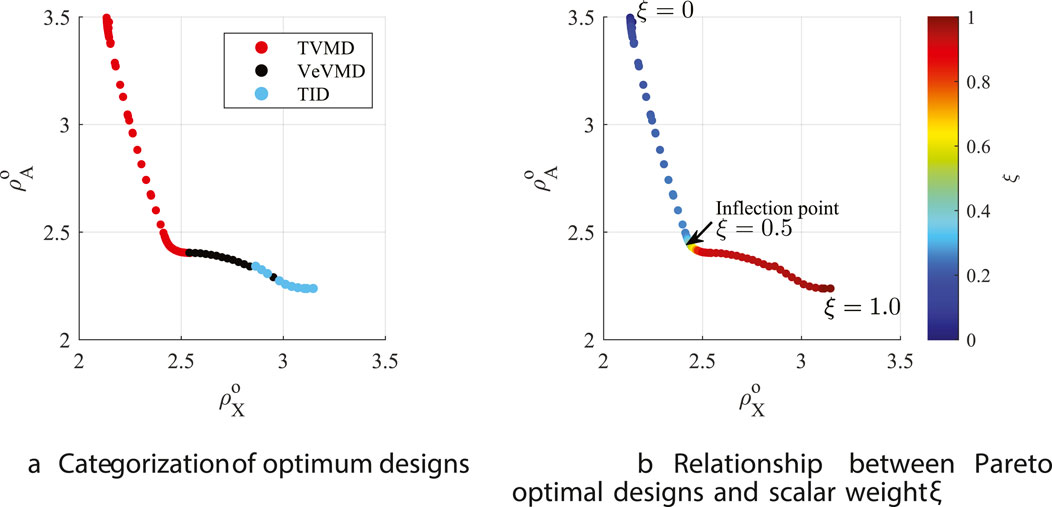
Figure 5. Pareto front
As shown in Figure 5B, the inclination of the Pareto front curve significantly changes at the inflection point of the curve at
3.5 Comparison between single- and multi-objective optimum designs
Here, we compare the single objective optimum designs and inflection point design derived from the multi-objective optimum design problem. Table 2 summarizes the closed form expressions for single objective optimum designs (Ikago et al., 2012a; Lazar et al., 2014; Saito et al., 2008; Hu et al., 2015). The superscript of the design variables, TVMD and TID, represents the device topologies. The subscript
To compare the performance of the inflection point design of the multi-objective optimum design problem and the solution obtained from fixed point methods, the values of design variables are determined under the constraint that all systems maintain an identical damping ratio
For the
was solved with respect to
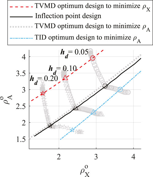
Figure 6 plots the
The inflection point design (solid black circle in Figure 6) improves
Figure 7A depicts the displacement amplification factors when
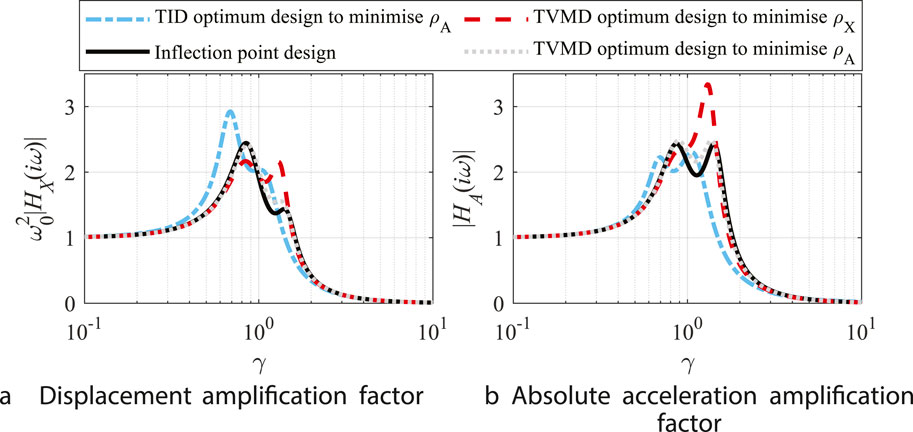
Figure 7. Amplification factors: (A) displacement amplification factor and (B) absolute acceleration amplification factor.
From Table 2, the single objective
Figure 8 demonstrates that the fixed-point TVMD acceleration control designs give good approximations of the inflection point designs in general cases, including those other than
3.6 Robustness of TVMD with respect to the variation in design variables
To examine the robustness of a TVMD with respect to the variation of design variables, Equation 18 defines two indices.
Since we examine TVMD exclusively,
Figures 9A and B show the contour of
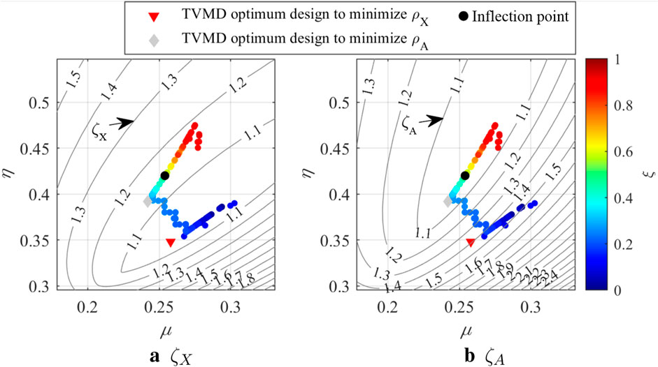
Figure 9. Performance indices: (A) displacement amplification factor and (B) absolute acceleration amplification factor.
4 Analytical example
4.1 Ten-story shear building
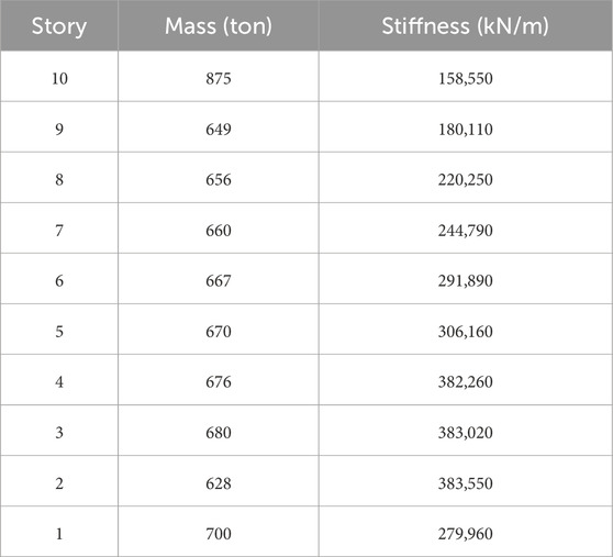
To examine the performance of inflection point design and fixed point designs in a multi-story structure, we use a ten-story benchmark shear building model presented by the Japan Society of Seismic Isolation (2013). Figure 10 shows the analytical model of the benchmark structure.
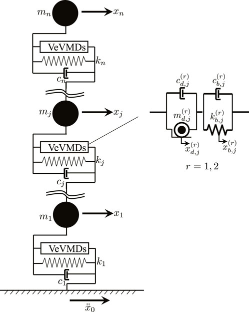
Figure 10. Ten-story benchmark shear building (Japan Society of Seismic Isolation, 2013).
4.2 VeVMD parameters
The structure is equipped with VeVMDs tuned to the first and second modes. The inertance, stiffness, damping coefficient of the damper parallel to the inerter, and that parallel to the spring in a VeVMD are
Similarly, letting the stiffness ratio and damping ratio for the VeVMD tuned to the
4.3 Damping ratio
Before designing VeVMDs, the total damping coefficient assigned to the devices is determined as shown in Equation 22.
Thus, Equation 23 holds.
The damping distribution factor
For a fixed-point design, substituting
4.4 Input ground motions
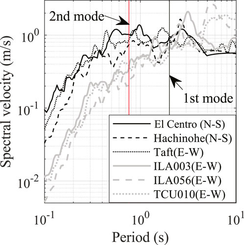
As for design ground motions, three historic ground motion records, three synthetic ground motions, and three long-period ground motion records (listed respectively in Tables 7–9) are used. The first six ground motions were selected in accordance with the practice in Japan, and three long-period ground motions (Xu et al., 2008) were added to examine the effect of long-period ground motion on the displacement control performance of TVMD. Figure 11 depicts the response velocity spectra of recorded ground motions (No. 1–3, 7–9).
When conducting seismic response analyses using normalized ground motion records, the variability in maximum response tends to be smaller when the records are normalized by PGV rather than by PGA, particularly for structures with natural periods of 2 s or longer (Editorial Committee of Structural Design Practice of High-rise Buildings, 2019). For this reason, it is standard practice in Japan to normalize ground motion records by PGV when designing high-rise buildings. Adopting this approach, the recorded ground motions (No. 1–3 and 7–9) are scaled such that their peak ground velocities (PGVs) are 0.5 m/s.
In Japanese structural design practice, artificial ground motions whose response spectra are compatible with the design response spectrum are used to avoid underestimating responses when the natural period of a building coincides with that of a notch in the spectra of recorded ground motions.
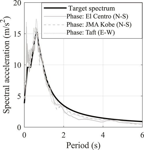
The synthetic ground motions are generated such that their response acceleration spectra are compatible with the design response acceleration spectra of Japan’s building code (Figure 12). They adopt the phase properties of recorded ground motions (Table 8).
The detailed parameters to derive the design spectrum can be found in Supplementary Figures S1 and S2 and Supplementary Table S1. Soil type 2 as the most common soil type in Japan is adopted for the surface subsoil type. The target spectrum shown in black solid line in Figure 12 is obtained by multiplying the response acceleration spectrum at the bed rock shown in Supplementary Figure S1 by the type 2 soil amplification factor shown in Supplementary Figure S2. As the amplitudes of the synthetic ground motions are determined by the target spectrum, their PGVs are not exactly 0.5 m/s (Table 8).
4.5 Analytical results and discussion
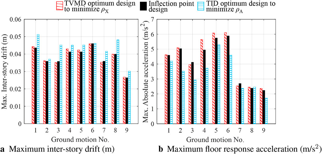
We first compare the seismic response analysis results with the damping coefficient allocated to the second mode
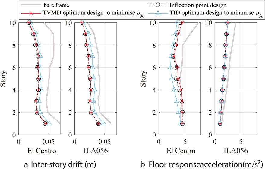
Figure 13. Maximum seismic responses (
Figures 15A and B plot
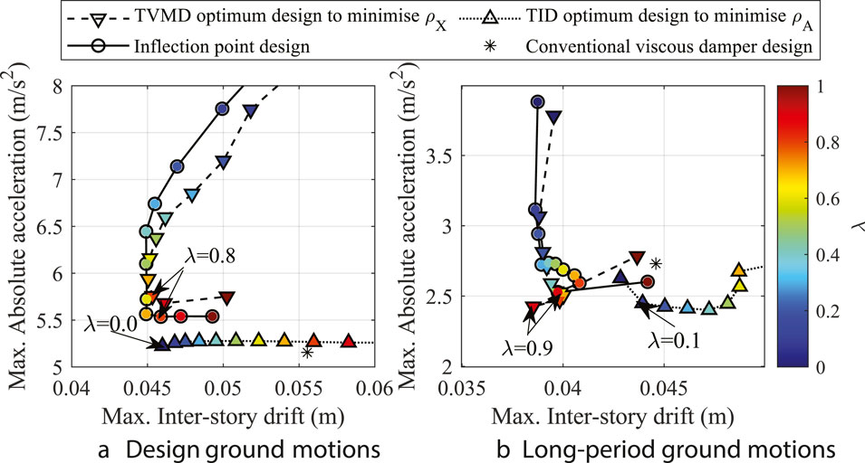
Figure 15. Performance curves: (A) design ground motions (Nos 1–6); (B) long-period ground motions (Nos 7–9).
5 Conclusion
This paper has examined the effect of damper arrangement in inerter-based structural DVAs. Therefore, a comprehensive multi-objective optimization was performed on a VeVMD with a device topology to encompass those of two major inerter-based structural DVAs—the TVMD and TID. Removing a damper arranged parallel to the spring in a VeVMD yields a TVMD device topology, while removing a damper arranged in parallel to the inerter yields a TID device topology. Multi-objective optimization to simultaneously minimize peak displacement and peak absolute acceleration amplification factors of a SDOF structure containing VeVMD subject to the constraint on the total supplemental damping coefficient revealed that the designs that has advantage in controlling displacement and absolute accelerations converge to TVMD and TID device topologies, respectively. There is an inflection point on the Pareto frontier curve where the inclination of its tangential line drastically changes. The Pareto optimum design on the inflection point is found to be robust against the variation of design variables, offering one of the best options for effective simultaneous control of displacement and floor response acceleration. The device topology yielded by the inflection point design is that of TVMD, and its solution can be approximated by the closed-form formula derived by the fixed-point method for a TVMD to minimize the peak absolute acceleration amplification factor.
An analytical example using a ten-story shear building model demonstrated that the multi-objective optimum designs to minimize peak amplification factors are effective in mitigating seismic responses. The inflection point design and fixed-point TVMD displacement control design performed effectively in mitigating displacement response, while fixed-point TID acceleration control design effectively mitigated floor response acceleration. This means that the performances of TVMD and TID with the same total damping coefficient are not inferior to one another. The inflection point design slightly outperformed fixed-point TVMD displacement control design for design ground motions, whereas there are cases in which fixed-point TVMD displacement control design outperformed the inflection point design for long-period ground motions. For such motions, the TVMD configuration designs generally outperform the conventional damper design in both inter-story drifts and absolute accelerations.
In this study, the device topology optimization was conducted on a SDOF structure and exclusively focused on the TVMD and TID. As for a MDOF structure, the effectiveness of IVCSs is also affected by the installation positions along the height, which should be further studied. Furthermore, topological configurations of IVCSs other than TVMD and TID should be considered in future studies.
Data availability statement
The raw data supporting the conclusions of this article will be made available by the authors, without undue reservation.
Author contributions
RX: investigation, methodology, visualization, writing–original draft, and writing–review and editing. KI: conceptualization, supervision, writing–original draft, and writing–review and editing.
Funding
The authors declare that financial support was received for the research, authorship, and/or publication of this article. The first author is supported by the scholarship provided by the Ministry of Education, Culture, Sports, Science, and Technology, Japan (scholarship number 211503).
Acknowledgments
The authors would like to thank Editage (www.editage.jp) for English language editing.
Conflict of interest
The authors declare that the research was conducted in the absence of any commercial or financial relationships that could be construed as a potential conflict of interest.
Generative AI statement
The author(s) declare that no Generative AI was used in the creation of this manuscript.
Publisher’s note
All claims expressed in this article are solely those of the authors and do not necessarily represent those of their affiliated organizations, or those of the publisher, the editors, and the reviewers. Any product that may be evaluated in this article, or claim that may be made by its manufacturer, is not guaranteed or endorsed by the publisher.
Supplementary material
The Supplementary Material for this article can be found online at: https://www.frontiersin.org/articles/10.3389/fbuil.2024.1508190/full#supplementary-material
References
Arakaki, T., Kuroda, H., Arima, F., Inoue, Y., and Baba, K. (1999). Development of seismic devices applied to ball screw: Part 1 basic performance test of rd-series. AIJ J. Technol. Des. 5, 239–244. doi:10.3130/aijt.5.239_1
Caicedo, D., Lara-Valencia, L., Blandon, J., and Graciano, C. (2021). Seismic response of high-rise buildings through metaheuristic-based optimization using tuned mass dampers and tuned mass dampers inerter. J. Build. Eng. 34, 101927. doi:10.1016/j.jobe.2020.101927
Cao, L., and Li, C. (2022). A high performance hybrid passive base-isolated system. Struct. Control Health Monit. 29, e2887. doi:10.1002/stc.2887
De Domenico, D., Ricciardi, G., and Takewaki, I. (2019). Design strategies of viscous dampers for seismic protection of building structures: a review. Soil Dyn. Earthq. Eng. 118, 144–165. doi:10.1016/j.soildyn.2018.12.024
Domenico, D. D., Deastra, P., Ricciardi, G., Sims, N., and Wagg, D. (2019). Novel fluid inerter based tuned mass dampers for optimised structural control of base-isolated buildings. J. Frankl. Inst. 356, 7626–7649. doi:10.1016/j.jfranklin.2018.11.012
Editorial Committee of Structural Design Practice of High-rise Buildings (2019). Structural design practice of high-rise buildings (in Japanese) (Building Center of Japan).
Fonseca, C. M., and Fleming, P. J. (1993). Genetic algorithms for multiobjective optimization: formulation, discussion, and generalization. Icga 93, 416–423.
Housner, G., Bergman, L., Caughey, T., Chassiakos, A., Claus, R., Masri, S., et al. (1997). Structural control: past, present, and future. J. Eng. Mech. 123, 897–971. doi:10.1061/(asce)0733-9399(1997)123:9(897)
Hu, Y., and Chen, M. (2015). Performance evaluation for inerter-based dynamic vibration absorbers. Int. J. Mech. Sci. 99, 297–307. doi:10.1016/j.ijmecsci.2015.06.003
Hu, Y., Chen, M., Shu, Z., and Huang, L. (2015). Analysis and optimisation for inerter-based isolators via fixed-point theory and algebraic solution. J. Sound Vib. 346, 17–36. doi:10.1016/j.jsv.2015.02.041
Hwang, J., Kim, J., and Kim, Y. (2007). Rotational inertia dampers with toggle bracing for vibration control of a building structure. Eng. Struct. 29, 1201–1208. doi:10.1016/j.engstruct.2006.08.005
Ikago, K., Saito, K., and Inoue, N. (2012a). Seismic control of single-degree-of-freedom structure using tuned viscous mass damper. Earthq. Eng. Struct. Dyn. 41, 453–474. doi:10.1002/eqe.1138
Ikago, K., Sugimura, Y., Saito, K., and Inoue, N. (2012b). Modal response characteristics of a multiple-degree-of-freedom structure incorporated with tuned viscous mass dampers. J. Asian Archit. Build. Eng. 11, 375–382. doi:10.3130/jaabe.11.375
Ishii, M., Kazama, H., Miyazaki, K., and Murakami, K. (2014). “Application of tuned viscous mass damper to super-high-rise buildings,” in Proceedings of the 6th world Conference of structural Control and health monitoring, (Barcelona, Sapin: International Center for Numerical Methods in Engineering CIMNE), 2825–2833.
Japan Society of Seismic Isolation (2013). Manual for design and fabrication for passive vibration control of structures. 3rd ed. (in Japanese).
Ji, X., Cheng, Y., and Hutt, C. (2020). Seismic response of a tuned viscous mass damper (TVMD) coupled wall system. Eng. Struct. 225, 111252. doi:10.1016/j.engstruct.2020.111252
Ji, X., Zhang, J., Ikago, K., Chakraborty, S., and Kanno, H. (2021). Tuned viscous mass damper (TVMD) coupled wall system for enhancing seismic performance of high-rise buildings. Eng. Struct. 240, 112307. doi:10.1016/j.engstruct.2021.112307
John, E., and Wagg, D. (2019). Design and testing of a frictionless mechanical inerter device using living-hinges. J. Frankl. Inst. 356, 7650–7668. doi:10.1016/j.jfranklin.2019.01.036
Kang, J., and Ikago, K. (2023). Seismic control of multidegree-of-freedom structures using a concentratedly arranged tuned viscous mass damper. Earthq. Eng. Struct. Dyn. 52, 4708–4732. doi:10.1002/eqe.3977
Keivan, A., Phillips, B. M., Ikenaga, M., and Ikago, K. (2017). Causal realization of rate-independent linear damping for the protection of low-frequency structures. J. Eng. Mech. 143, 04017058. doi:10.1061/(asce)em.1943-7889.0001259
Kida, H., Ikago, K., and Inoue, N. (2012). “Applicability of force-restricted tuned viscous mass dampers to high-rise buildings subjected to long-period ground motions,” in Proceedings of the 15th world conference on earthquake engineering (Lisbon, Portugal: LISBOA).
Kim, J., Ryu, J., and Chung, L. (2006). Seismic performance of structures connected by viscoelastic dampers. Eng. Struct. 28, 183–195. doi:10.1016/j.engstruct.2005.05.014
Lazar, I., Neild, S., and Wagg, D. (2014). Using an inerter-based device for structural vibration suppression. Earthq. Eng. Struct. Dyn. 43, 1129–1147. doi:10.1002/eqe.2390
Licari, M., Sorace, S., and Terenzi, G. (2015). Nonlinear modeling and mitigation of seismic pounding between r/c frame buildings. J. Earthq. Eng. 19, 431–460. doi:10.1080/13632469.2014.984370
Lobato, F., and Steffen, Jr V. (2017). Multi-objective optimization problems: concepts and self-adaptive parameters with mathematical and engineering applications. Springer.
Luo, H., and Ikago, K. (2021). Unifying causal model of rate-independent linear damping for effectively reducing seismic response in low-frequency structures. Earthq. Eng. Struct. Dyn. 50, 2355–2378. doi:10.1002/eqe.3450
Luo, H., Ikago, K., Chong, C., Keivan, A., and Phillips, B. (2019). Performance of low-frequency structures incorporated with rate-independent linear damping. Eng. Struct. 181, 324–335. doi:10.1016/j.engstruct.2018.12.022
Ma, R., Bi, K., and Hao, H. (2021). Inerter-based structural vibration control: a state-of-the-art review. Eng. Struct. 243, 112655. doi:10.1016/j.engstruct.2021.112655
Makris, N., and Kampas, G. (2016). Seismic protection of structures with supplemental rotational inertia. J. Eng. Mech. 142, 04016089. doi:10.1061/(asce)em.1943-7889.0001152
Makris, N., and Moghimi, G. (2022). Response of seismic isolated structures with supplemental rotational inertia. Earthq. Eng. Struct. Dyn. 51, 2956–2974. doi:10.1002/eqe.3709
Marian, L., and Giaralis, A. (2014). Optimal design of a novel tuned mass-damper-inerter (TMDI) passive vibration control configuration for stochastically support-excited structural systems. Probabilistic Eng. Mech. 38, 156–164. doi:10.1016/j.probengmech.2014.03.007
Marler, R., and Arora, J. (2010). The weighted sum method for multi-objective optimization: new insights. Struct. Multidiscip. Optim. 41, 853–862. doi:10.1007/s00158-009-0460-7
Mazza, F., and Labernarda, R. (2020). Magnetic damped links to reduce internal seismic pounding in base-isolated buildings. Bull. Earthq. Eng. 18, 6795–6824. doi:10.1007/s10518-020-00961-6
Nakamura, Y., Fukukita, A., Tamura, K., Yamazaki, I., Matsuoka, T., Hiramoto, K., et al. (2014). Seismic response control using electromagnetic inertial mass dampers. Earthq. Eng. Struct. Dyn. 43, 507–527. doi:10.1002/eqe.2355
Nakamura, Y., Watanabe, H., and Kawamata, S. (1988). “Seismic response control of structures by accelerated liquid mass damper,” in Proceedings of the 9th world conference on earthquake engineering, 785–790.
Ogino, M., and Sumiyama, T. (2014). “Structural design of a high-rise building using tuned viscous mass dampers installed across three consecutive sotreys,” in Proceedings of the 12th international Conference on computational structures Technology (Naples, Italy), 225. doi:10.4203/ccp.106.225
Pan, C., and Zhang, R. (2018). Design of structure with inerter system based on stochastic response mitigation ratio. Struct. Control Health Monit. 25, e2169. doi:10.1002/stc.2169
Pan, C., Zhang, R., Luo, H., Li, C., and Shen, H. (2018). Demand-based optimal design of oscillator with parallel-layout viscous inerter damper. Struct. Control Health Monit. 25, e2051. doi:10.1002/stc.2051
Papageorgiou, C., Houghton, N., and Smith, M. (2009). Experimental testing and analysis of inerter devices. J. Dyn. Syst. Meas. Control 131, 011001. doi:10.1115/1.3023120
Qiao, H., Huang, P., Domenico, D. D., and Wang, Q. (2023). Targeted modal response control of structures with inerter-based vibration absorbers considering modal interaction effects. J. Build. Eng. 64, 105692. doi:10.1016/j.jobe.2022.105692
Saito, K., Sugimura, Y., Nakaminami, S., Kida, H., and Inoue, N. (2008). “Vibration tests of 1-story response control system using inertial mass and optimized softy spring and viscous element,” in Proceedings of the 15th world conference on earthquake engineering (Beijing, China: WCEE).
Saitoh, M. (2012). On the performance of gyro-mass devices for displacement mitigation in base isolation systems. Struct. Control Health Monit. 19, 246–259. doi:10.1002/stc.419
Smith, M. (2002). Synthesis of mechanical networks: the inerter. IEEE Trans. automatic control 47, 1648–1662. doi:10.1109/tac.2002.803532
Steuer, R. (1986). “Multiple criteria optimization: theory, computation, and applications,” in Wiley series in probability and mathematical statistics.
Sugimura, Y., Goto, W., Tanizawa, H., Saito, K., and Ninomiya, T. (2012). “Response control effect of steel building structure using tuend viscous mass damper,” in Proceedings of the 15th international Conference on earthquake engineering (Lisbon, Portugal: LISBOA).
Taflanidis, A., Giaralis, A., and Patsialis, D. (2019). Multi-objective optimal design of inerter-based vibration absorbers for earthquake protection of multi-storey building structures. J. Frankl. Inst. 356, 7754–7784. doi:10.1016/j.jfranklin.2019.02.022
Wang, B., Ikago, K., and Kezuka, S. (2024). Causal rate-independent damping device using a rotary inerter damper. Front. Built Environ. 10, 1411170. doi:10.3389/fbuil.2024.1411170
Wang, F., Hong, M., and Lin, T. (2011). Designing and testing a hydraulic inerter. Proc. Institution Mech. Eng. Part C J. Mech. Eng. Sci. 225, 66–72. doi:10.1243/09544062jmes2199
Watanabe, Y., Ikago, K., Inoue, N., Kida, H., Nakaminami, S., Tanaka, H., et al. (2012). “Full-scale dynamic tests and analytical verification of a force-restricted tuned viscous mass damper,” in 15th World Conference On Earthquake Engineering (Lisbon, Portugal: LISBOA).
Xu, L., Hu, J., and Xie, L. (2008). On characteristics of ground motion parameters for special long-period ground motions (in Chinese). J. Earthq. Eng. Eng. Vib. 28, 20–27.
Zhang, R., Zhao, Z., Pan, C., Ikago, K., and Xue, S. (2020). Damping enhancement principle of inerter system. Struct. Control Health Monit. 27, e2523. doi:10.1002/stc.2523
Keywords: inerter, tuned viscous mass damper, tuned inerter damper, tuned mass damper, multi-objective optimization, Pareto front
Citation: Xie R and Ikago K (2024) Device topology optimization for an inerter-based structural dynamic vibration absorber. Front. Built Environ. 10:1508190. doi: 10.3389/fbuil.2024.1508190
Received: 09 October 2024; Accepted: 26 November 2024;
Published: 24 December 2024.
Edited by:
Nikos D. Lagaros, National Technical University of Athens, GreeceReviewed by:
Tadesse Gemeda Wakjira, University of British Columbia, Okanagan Campus, CanadaRodolfo Labernarda, University of Calabria, Italy
Copyright © 2024 Xie and Ikago. This is an open-access article distributed under the terms of the Creative Commons Attribution License (CC BY). The use, distribution or reproduction in other forums is permitted, provided the original author(s) and the copyright owner(s) are credited and that the original publication in this journal is cited, in accordance with accepted academic practice. No use, distribution or reproduction is permitted which does not comply with these terms.
*Correspondence: Kohju Ikago, a29qdS5pa2Fnby5lOEB0b2hva3UuYWMuanA=
 Ruihong Xie
 Kohju Ikago