- 1Department of Civil Engineering, Karunya Institute of Technology and Sciences, Coimbatore, India
- 2College of Engineering and Technology, American University of the Middle East, Kuwait
- 3Department of ECE, Karunya Institute of Technology and Sciences, Coimbatore, India
The use of back-to-back built-up channel beams in cold-formed steel (CFS) structures is steadily rising. The growing demand for CFS sections as a cost-effective design solution has driven the development of these CFS built-up sections. Despite this, there has been limited research on the performance of mild steel (MS) based CFS at high temperatures, particularly regarding its flexural behavior. This study thoroughly explores the behavior of MS-based CFS beams with different spans under high temperatures, followed by cooling with air or water. It assesses the impact of thermal loading and evaluates the effectiveness of these cooling methods. Experimental findings are validated and analyzed in conjunction with Finite Element Modeling (FEM) using ABAQUS and the Direct Strength Method (DSM). The study also conducts a parametric analysis to determine how the varying span that affects flexural capacity of beam. Among beams heated to the same temperature, those cooled with water exhibit slightly lower load capacities than those cooled with air. The maximum load observed is 91.21 kN for the reference specimen, while the minimum load is 39.82 kN for the specimen heated for 90 min and cooled with water, resulting in a 78.45% difference between these values. Additionally, as heating duration increases, ductility of beam also increases. Various failure modes are observed based on different heating and cooling conditions across different beam spans. This study offers valuable insights into the performance of MS-based CFS beams under thermal stress and different cooling conditions, providing important data for structural design and safety in construction.
1 Introduction
Cold-formed steel (CFS) is gaining importance in construction because of its many advantageous properties. Unlike hot-rolled steel, CFS is manufactured without heat, making it a more cost-effective option. However, CFS is susceptible to fire damage, making it essential to understand its behavior in fire scenarios for effective risk management.
The environmental impact of construction materials and methods is becoming an increasingly important consideration in modern structural design. CFS sections offer several advantages from a sustainability perspective, which makes them highly suitable for eco-conscious construction projects. CFS is primarily made from recycled steel, and steel itself is one of the most recycled materials globally. This means that CFS sections can be reused and repurposed at the end of their life cycle, contributing to the reduction of waste and promoting a circular economy within the construction industry. In the context of fire-resistance scenarios, the use of CFS beams provides additional environmental benefits due to their high strength-to-weight ratio, which leads to reduced material usage in comparison to other traditional construction materials like concrete or timber. The lighter weight of CFS beams results in lower transportation energy and reduced carbon emissions during the construction process. Additionally, the precision involved in fabricating CFS members helps minimize material wastage on construction sites, further contributing to sustainable building practices. As the demand for eco-friendly materials and construction methods continues to grow, CFS sections offer a viable solution due to their recyclability, reduced carbon footprint, and adaptability in fire-resistant design.
MS-based CFS sections are generally more cost-effective than hot-rolled steel sections, concrete, or traditional fire-resistant materials. The manufacturing process of CFS involves cold-forming thin steel sheets, which reduces the amount of raw material required and lowers production costs. Furthermore, the ability to produce customized sections tailored to specific project needs results in reduced material wastage, adding to the cost savings. These benefits make CFS sections a competitive option for cost-conscious projects, particularly in low- and mid-rise buildings where lightweight structural elements are advantageous. CFS sections are lightweight and easy to transport, which reduces shipping costs and facilitates faster on-site installation. The reduced weight of CFS beams also lowers the demand for heavy lifting equipment and simplifies the overall construction process, leading to shorter construction timelines and reduced labor costs. Additionally, the modular nature of CFS sections allows for prefabrication, which can further streamline construction schedules and improve overall project efficiency.
Aktepe & Guldur Erkal (Aktepe and Guldur Erkal, 2023) extensively investigated the flexural behavior of CFS beams with hat shapes and geometric imperfections, concluding that initial imperfections significantly impact the flexural performance. Their research highlighted the importance of accounting for initial imperfections in assessing the flexural strength of sections. Additionally, they tested CFS tubular beams for flexural behavior and conducted reliability analysis, demonstrating that the mean moment capacity was not dependent on any single variable or a combination of variables, thus validating the reliability analysis.
In another study, Jaya kumar et al. (2023a) examined the post-fire flexural behavior of CFS beams and found that an increased temperature exposure and duration resulted in decreased load-carrying capacity. This research enhanced the understanding of CFS beams’ flexural behavior following fire exposure. Recently, Ma et al., 2024 conducted experimental and theoretical investigations into the flexural performance of thin-walled steel laminated bamboo truss beams. Their study showed that increasing the beam’s width, height, and the number of self-drilling screws significantly improved the composite truss beam’s bending resistance. Yang et al. (2024) investigated the flexural buckling behavior of CFS back-to-back built-up columns with Σ-sections, revealing that reducing fastener spacing and increasing shear resistance could enhance load-bearing capacity. These studies emphasized the importance of the number and spacing of screws in determining the flexural strength of CFS beams. Sangeetha et al. (2021) studied the behavior of CFS hollow beams with perforations under flexural loading, finding that the flexural strength of rectangular hollow beams increased by 41% compared to square hollow beams.
Karthik et al. (2022) explored the flexural response of CFS ferritic stainless steel (CFSSS) closed-section built-up beams, providing reliable data on the flexural behavior of CFSSS closed-section built-up beams, it is previously missing data from the literature. Yılmaz et al. (2024) examined the behavior of CFS sigma and lipped channel section beam columns and found that the FEA-AISI-S100 (AISI, 2010) error rate decreased as the length of sigma sections increased. Anbarasu et al. (2021) investigated the effect of external strengthening on the flexural strength of CFS beams, concluding that certain strengthening techniques could potentially improve the flexural strength of CFS beams.
Despite these advancements, significant research gaps remain, especially concerning the flexural response of mild steel (MS) based CFS back-to-back built-up sections under elevated temperatures. Additionally, there is a need to understand the impact of fire exposure on CFS built-up beams and analyze their post-fire behavior using the Direct Strength Method (DSM). Existing literature has primarily focused on the behavior of hot-rolled steel sections under high temperatures, which are known for their superior fire resistance due to their thicker profiles and higher thermal mass. However, these benefits come at the expense of increased material and construction costs. In contrast, CFS sections offer several advantages such as lower material costs, ease of installation, and quicker construction times. However, their reduced thermal mass results in a faster rise in temperature during fire exposure, which can significantly affect their load-bearing capacity and overall structural integrity. This trade-off between cost and fire performance highlights the importance of understanding the specific behavior of CFS sections under thermal stress.
This study aims to investigate the flexural behavior of MS-based CFS beams under elevated temperatures and different cooling methods across various spans. The anticipated outcomes are expected to provide valuable insights for design practices and facilitate a comparative analysis between experimental findings and numerical simulations. Recognizing the challenges of experimental investigations, this study highlights the importance of numerical simulations in comprehensively understanding CFS beam behavior under fire conditions. The novelty of this study lies in its comprehensive investigation of the flexural performance of MS-based CFS beams subjected to elevated temperatures, followed by different cooling methods (air and water). By combining experimental testing, FEM, and parametric analysis, this study fills a significant gap in the current body of knowledge on the thermal behavior of CFS sections. The study provides valuable data on failure modes, ductility, and load-bearing capacities, contributing to the ongoing efforts to develop fire-resistant design strategies for CFS structures. Moreover, this research offers a detailed comparison between different cooling methods and heating durations, offering practical insights that can be applied to optimize the fire performance of CFS beams in real-world construction scenarios. This study also enhances the understanding of how CFS beams perform under high temperatures relative to hot-rolled sections across various spans, highlighting both the benefits of cost-efficiency and the challenges of reduced fire resistance. By addressing these critical aspects, the findings of this research will aid in the development of more resilient, cost-effective, and fire-safe building designs using CFS sections.
2 Materials and methods
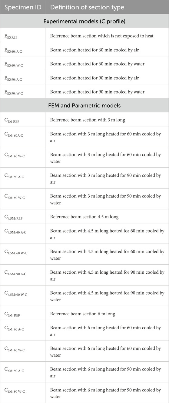
This study utilized C-shaped, back-to-back connected CFS sections made of MS material, of grade 355, with a length of 1.5 m. The dimensions of the C channel are shown in Figure 1A. Figure 1B depicts cross sectional view of the beam section. The sections were heated to specified temperatures and then cooled using either air or water. In the experimental setup, a controlled heating environment is utilized to ensure an uniform temperature distribution as possible across the length of the CFS beams. An electric furnace, following the specifications of (ISO 834-1, 1999), was used to heat the beams for 60 (925°C) and 90 (986°C) minutes. The furnace gets automatically cut off after the desired temperature is achieved. Heating temperature and surface temperature of the specimen can be monitored in the control panel attached in the furnace. Sections were kept inside the furnace and made to heat up to desired temperature and time. After the specimens were heated to the desired temperature, they were allowed to cool down to ambient temperature using air (Jaya kumar et al., 2023b) or water (Zhou et al., 2021). In the case of specimens cooled down using air, the specimens were allowed to cool down to ambient temperature. In the case of specimens cooled down using water, specimens were taken out from the furnace and were sprayed using water until it cools down to ambient temperature. The C sections were connected back-to-back with self-tapping screws, each 6 mm in diameter. Pinned and roller supports were installed at both ends to provide the necessary support conditions. The material properties of the sections are detailed in Table 1.
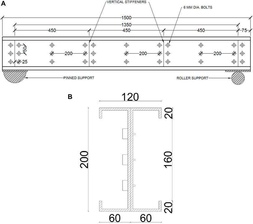
Figure 1. (A) Dimensions of channel used for experimental tests, (B) Cross section of beam section. (*All dimensions are in mm).
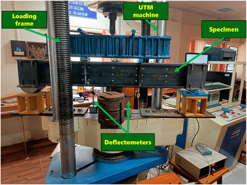
After the heating and cooling phases, the beams were tested on a Universal Testing Machine (UTM) under two-point loading conditions. Vertical stiffeners, 2 mm thick, were welded to the beams at both supports and two loading points, as shown in Figure 1A. These stiffeners were incorporated to prevent twisting and lateral buckling during testing. The two-point loading setup was used to simulate the flexural behavior of the beams. Specimen IDs and abbreviations are listed in Table 2. Deflectometers were placed beneath the bottom flange of the section at both loading points and the midpoint of the beam. Linearly variable differential transducers (LVDTs) were attached to the side of the web of the beam. Additionally, this study includes an analytical and parametric investigation for beams with spans of 3, 4.5, and 6 m, as depicted in Figures 2A–C. The experimental setup is shown in Figure 3.
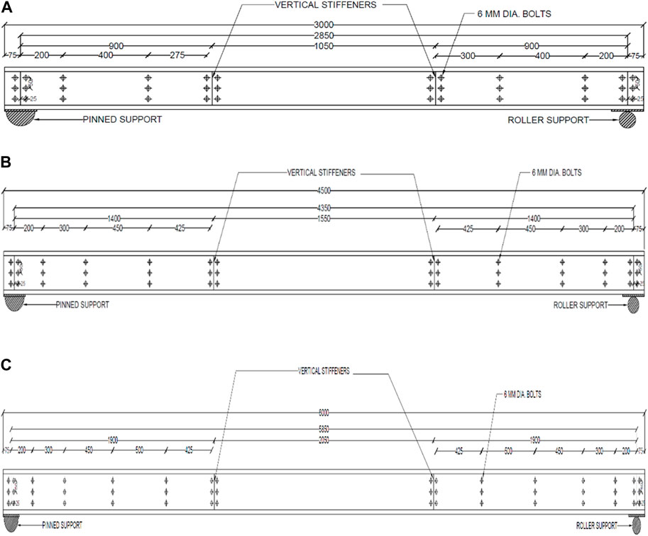
Figure 2. (A) Dimensions of 3,000 mm channel, (B) Dimensions of 4,500 mm channel, (C) Dimensions of 6,000 mm channel (*All dimensions are in mm).
The experiments conducted in this study were performed on CFS beams with specific dimensions and spans, representative of medium to small-scale structural components. While the results provide important data on the behavior of CFS beams under fire conditions, caution must be exercised when extrapolating these findings to larger-scale structures such as high-rise buildings or long-span industrial frameworks. Larger structures are subject to more complex loading conditions, and the behavior of CFS sections may differ due to variations in thermal expansion, load distribution, and stress concentration that were not fully captured in the experimental setup. Additionally, the use of back-to-back built-up channel sections, while common in smaller and medium-sized structures, may face different performance challenges when applied to larger-scale systems. Future research is necessary to validate the findings of this study across a broader range of beam sizes and structural configurations to confirm their applicability to large-scale construction.
3 Results and discussion
3.1 Physical changes
3.1.1 After heating
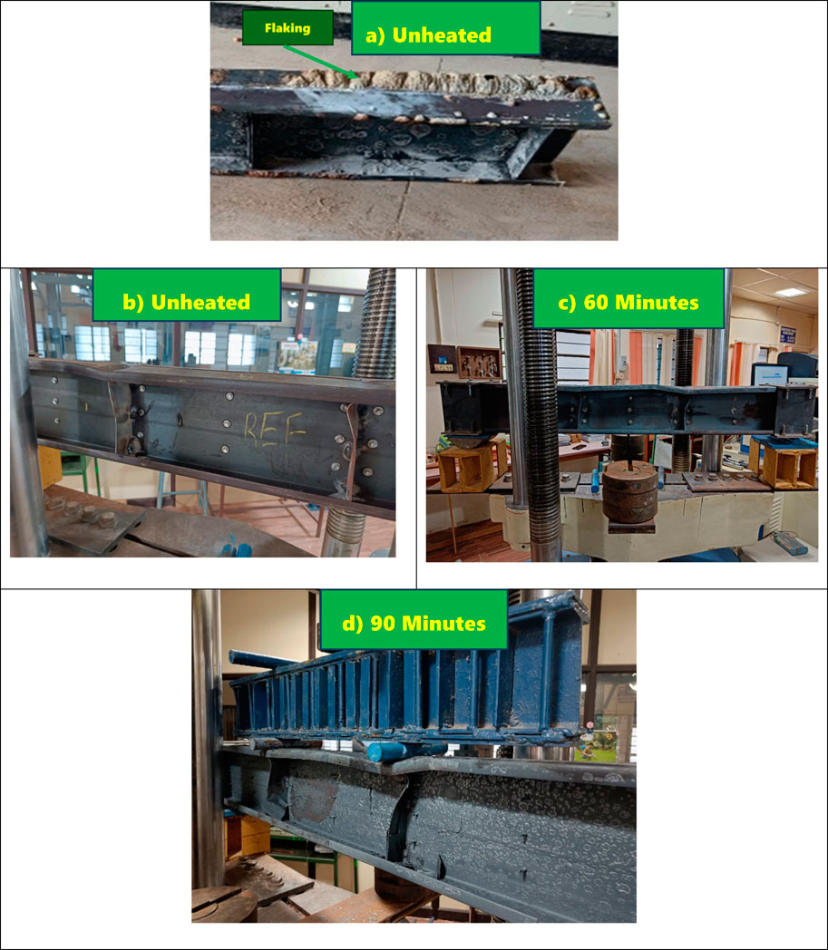
Before heating, the beam sections were uniformly dark grey in color, as depicted in Figure 3. After the heating process, visible flaking appeared on the surface, as shown in Figure 4A). At lower temperatures, the color shifted to a light blue hue, and with increased heating duration, the color turned light blue with brown patches. Additionally, noticeable brown dust was observed on the surface of all specimens. Flaking was noted to be on the top surface of the beam section after heating as seen in the figure. During the heating phase, the steel expands, and upon cooling, it contracts. This process can lead to surface-level flaking as the material undergoes rapid thermal cycling, especially if cooled with water, causing differential expansion and contraction rates in different sections of the beam. The difference in temperature between the surface and the core of the steel section (due to heating and subsequent cooling) creates thermal gradients. These gradients can cause residual stresses within the material, which may result in localized flaking, particularly in regions experiencing high thermal stress.
3.1.2 After testing
After testing, the specimens displayed distortional buckling across all heating durations. Buckling was particularly noticeable on the stiffeners located beneath the loading points, as depicted in Figures 4B–D. Distortional buckling occurred in the middle region of the beams, indicating compression failure at the top flange. The presence of additional stiffeners at the supports and restrained bearings effectively mitigated lateral-torsional buckling.
This form of buckling involves the deformation of the cross-sectional shape of the beam, specifically affecting the flanges and lips of the CFS sections. The onset and progression of distortional buckling in CFS beams can be attributed to a combination of factors, including thermal stresses, elevated temperatures, and material degradation under fire conditions. The thermal loading applied in this study caused significant changes in the mechanical properties of the CFS beams. As temperatures increased, the stiffness and strength of the steel sections progressively decreased. This reduction in material properties exacerbated the susceptibility to distortional buckling, particularly in beams exposed to prolonged heating durations. The results indicate that as the beams reached critical temperature thresholds, distortional buckling was initiated and progressed rapidly, leading to structural failure. As the temperature increased, the yield strength and elastic modulus of the steel significantly decreased. This made the flanges and lips of the CFS sections more vulnerable to deformation under load. The thin-walled nature of CFS sections makes them inherently prone to local and distortional buckling. Even minor geometric imperfections, such as slight variations in flange width or lip depth, can lead to stress concentrations that accelerate the onset of buckling under thermal loads.
The insights gained from this study can inform future design improvements for CFS structures in fire-prone areas. For example, the observed failure modes can guide engineers in selecting appropriate cooling methods during fire suppression, as well as designing CFS members that incorporate stiffeners or fire-resistant coatings to enhance structural resilience. Additionally, the findings can be integrated into the development of more robust fire safety codes and standards, ensuring that CFS members are designed with adequate protection against distortional buckling and other fire-related failure modes.
By understanding the progression of distortional buckling and employing mitigation strategies, designers can significantly improve the fire resistance of CFS structures, ensuring that they maintain their load-bearing capacity even under extreme thermal conditions.
3.2 Load deflection
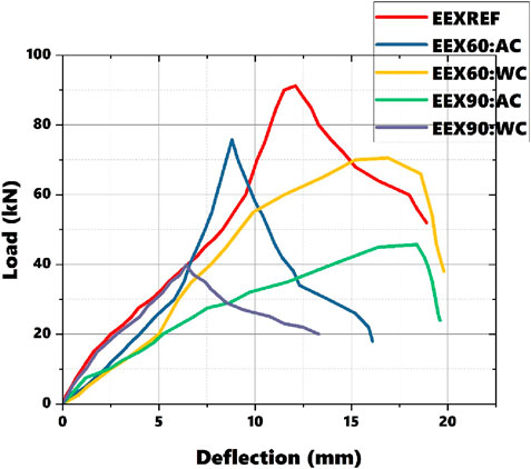
Figure 5 presents the load-deflection graphs obtained from the experimental testing of beam sections. The load is measured in kN, and deflection is in mm. This graph is crucial for understanding how a material or structure deflects under an applied load. In the graphs labeled EEX60: A-C, “60” denotes sections heated for 60 min and A-C denote cooled with air. According to the graph, it is evident that the load decreases with increasing temperature (Sabu Sam et al., 2024a). Among beams heated to the same temperature, sections cooled with water show slightly lower loads compared to those cooled with air. Water cooling typically causes a more rapid temperature drop compared to air cooling. This rapid cooling can induce significant thermal shock in the CFS beams, leading to high thermal gradients and residual stresses. These thermal stresses can adversely affect the material properties, potentially causing additional deformation or premature failure. Water has a much higher heat transfer coefficient than air, resulting in a faster cooling rate. While this might seem advantageous for quickly lowering the temperature, it can be detrimental to the structural integrity of the beam due to the reasons mentioned above. Air cooling, being slower, allows for a more gradual temperature reduction, which reduces the likelihood of inducing excessive thermal stresses.
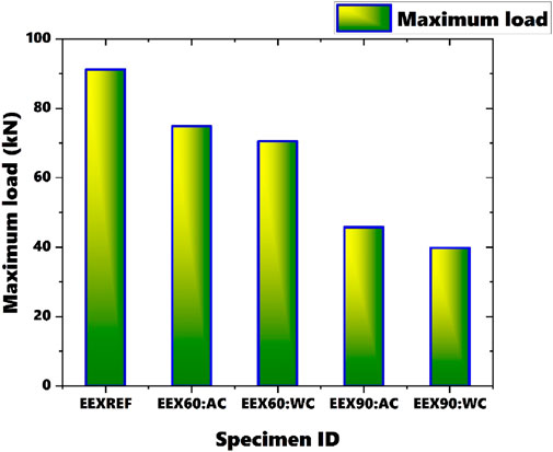
The maximum load observed is 91.21 kN for the reference specimen, while the minimum load is 39.82 kN for the specimen heated for 90 min and cooled with water, resulting in a 78.45% difference between these values. There is a significant decrease in load capacity noted for the section heated for 60 min and cooled with water, showing a 5.93% difference in load capacity compared to the sections heated for 60 min and cooled with air. Even for the section heated for 90 min, the specimen cooled with water demonstrates lower load capacity compared to the specimen cooled with air. The difference in load carrying capacity between the reference specimen and the section heated for 90 min suggests that failure initiation is influenced by factors beyond just heating and cooling, such as material degradation due to prolonged exposure to high temperatures.
The load-deflection diagram illustrates the ultimate load capacity of each beam specimen, as shown in Figure 6. It was observed across all sections that failure initiation resulted from the combined effects of applied load, material properties, and geometric characteristics of the beams.
3.3 Stiffness
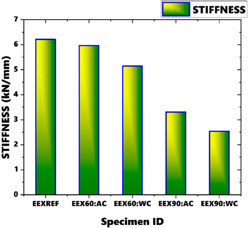
Stiffness, calculated from the load-deflection diagram by determining the slope of the linear portion of the curve (Equation 1), is a fundamental property that characterizes a material’s response to external forces. It plays a crucial role in material selection for specific applications and aids in understanding material behavior under sustained loading. Stiffness values of beams subjected to various durations of heating are presented in Figure 7, with stiffness values given in kN/mm. In a stress-strain curve or a load-displacement curve, the yield point is where plastic deformation starts, and the ultimate point is where failure occurs. For each specimen, Ultimate load is taken and is divided by corresponding displacement to get stiffness values from load deflection diagrams.
From the figure, it is evident that stiffness decreases as the duration of heating increases. The reference section exhibits the highest stiffness, while the section heated for 90 min and cooled using water shows the lowest stiffness, with a difference of 83.89% between these two values. A significant decrease in stiffness is observed for sections heated for 90 min. Additionally, there is a difference of 57.17% has been noted in stiffness between sections heated for 60 min and 90 min and cooled using air.
Stiffness, k is given by:
Where:
F is the applied load.
δ is the resulting displacement.
3.4 Ductility factor
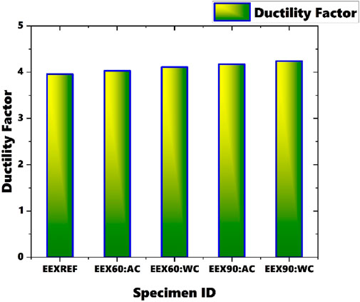
The ability of a material to undergo plastic deformation prior to failure is commonly referred to as its ductility factor (Sam et al., 2024a). This factor is typically quantified as the ratio of displacement at a specified strength or deformation level to the displacement at the yield point, known as the ductility ratio (Equation 2). For each specimen, Ultimate displacement is taken and is divided by yield displacement to get ductility factor values from load deflection diagrams. Materials with high ductility can undergo significant plastic deformation before reaching failure. Figure 8 illustrates the ductility factor obtained for all beam sections subjected to various durations of heating. It is observed that as the duration of heating increases, the ductility factor also increases. The lowest ductility factor is observed for the reference beam section, while the highest is observed for the beam section heated for 90 min and cooled using water. There is a difference of 43.9% has been observed between the ductility factor of the reference section and the section heated for 90 min and cooled using water. With prolonged heating, the beam experiences more pronounced changes in material properties, potentially leading to increased ductility. Subsequent cooling with water likely induces a more rapid and substantial decrease in temperature, further affecting material properties and potentially enhancing the ductility. The rapid cooling induced by water quenching can also lead to a more uniform redistribution of stresses within the material. As the steel cools quickly, there is less time for localized stress concentrations to develop, which can prevent the early onset of localized failures or brittle fracture. This allows the material to undergo more significant deformation, contributing to an increase in ductility. The more controlled cooling process allows the material to retain more of its ductile properties, as rapid cooling can embrittle the steel. Air-cooled specimens generally maintain higher load capacities due to reduced thermal shock and material degradation, while water-cooled specimens show a decrease in load capacity due to rapid cooling-induced stresses. As the beams are heated, residual stresses induced during manufacturing or previous loading cycles may partially relax. This relaxation process can cause a redistribution of stresses within the beam, potentially reducing stress concentrations and ultimately increasing overall ductility.
Where:
Yield Displacement- Determined from the load-displacement curve as the displacement corresponding to the yield load.
Ultimate Displacement- Taken as the maximum displacement recorded before the failure of the beam.
Table 3 shows coefficient of variation calculated for various experimental results of 1.5 long beam sections subjected to various durations of heating and cooling.
Using MS-based CFS sections can lead to cost savings in fire-protection systems due to their inherent versatility and adaptability. As shown in this study, CFS beams cooled with air exhibit a more gradual decrease in load-bearing capacity compared to water-cooled beams, suggesting that air cooling systems may be sufficient in certain cases, depending on the structure’s fire risk profile. This could reduce the need for expensive, elaborate fire suppression systems that rely on water, such as sprinkler systems, particularly in low-rise or mid-rise buildings where the fire risk is lower. CFS sections also offer long-term economic advantages due to their durability and corrosion resistance, particularly when galvanized or treated with appropriate coatings. The reduced maintenance requirements and extended lifespan of CFS structures contribute to lower long-term costs, making them a cost-effective choice for building owners. Additionally, as sustainability becomes a more pressing concern in the construction industry, the recyclability of steel positions CFS as an eco-friendly option, which may yield cost benefits through green building certifications or incentives for sustainable construction.
4 Finite element modelling
Parametric analysis and FEM modeling of beam sections were conducted using ABAQUS software (Abaqus analysis user’s manual, 2018). These simulations replicate the dimensions, support conditions, and loading conditions utilized in the experimental setup to ensure consistency and accuracy in the computational analysis. This approach facilitates the validation of numerical analysis. The initial step involved creating 2D representations of the beam sections, which were then converted into 3D models. This meticulous process ensured that the simulations closely emulated the real-world conditions observed in the experiments, enabling accurate analysis and comparison between experimental and numerical results. By maintaining the same setup conditions in both experimental and FEM analyses, this study aimed to achieve reliable and consistent validation of the computational models.
4.1 Material properties
The material properties utilized for the analysis of MS-based CFS beam sections were derived from temperature-dependent coupon test results, as outlined by (Jaya Kumar et al., 2023a). This coupon testing was done after heating and cooling under similar conditions as in this study and these values were used to simulate similar heating and cooling in FEM analysis. These properties include crucial parameters essential for the modeling process. Based on these material properties, an engineering stress-strain curve was initially generated. This curve was subsequently converted into a true stress-strain curve. This conversion is essential for accurately depicting the material behavior under varying loading conditions, especially at elevated temperatures. It ensures that the simulation outcomes closely mirror real-world observations, thereby enhancing the reliability and validity of the analysis. Table 4 shows the material properties of sections used for FEM analysis.
4.2 Element type and meshing
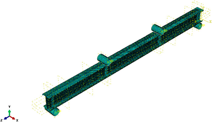
In the modeling process of all components of MS-based CFS beam sections, S4R element is utilized, it is a widely acknowledged element for accurately representing these beam types based on previous studies (Roy et al., 2021), (Sabu Sam et al., 2023). The selection of mesh size in FE analysis holds significant importance as it directly impacts computation time and result accuracy. Following prior research and literature (Selvaraj and Madhavan, 2019), (Sabu Sam et al., 2024b), a mesh size of 5 × 5 mm is adopted for this investigation. Figure 9 depicts the meshed-up beam section. To replicate the presence of self-tapping screws and their interactions within the beams, tie constraints are implemented during the modeling process. This ensures that the simulation accurately captures the behavior of the beams, accounting for the presence and effects of screws within the structural system.
4.3 Loading and boundary conditions
To ensure the accurate application of loading and boundary conditions, reference points were precisely defined at the center of the loading points and supports. During the meshing process, two node sets were established, specifying degrees of freedom for translation and rotation. The analysis began with a linear bifurcation analysis, followed by a nonlinear analysis utilizing the Riks method (Sam et al., 2024b). Pinned and roller supports were strategically applied at both ends of the specimens to replicate real-world conditions effectively. Eigenvalue analysis was conducted to address geometric imperfections in the FE models, enhancing the accuracy of structural behavior representation. Through linear bifurcation analysis, critical buckling modes were identified, providing valuable insights into potential failure modes under varied loading conditions. In the nonlinear analysis phase, the Modified Riks technique was employed to accurately capture complex behaviors and post-buckling responses. This sophisticated approach enabled the simulation of structural instability and large deformations, crucial for comprehending the behavior of MS-based CFS beam sections under diverse loading scenarios.
The back-to-back CFS channel beams were connected using self-tapping screws in the experimental setup. To replicate this in FEA, the connections were modeled to accurately capture the behavior of the screws and their interaction with the CFS beams. The self-tapping screws, which fastened the channels, were represented in the FEA model using tie constraints. These constraints ensured that the connected surfaces at the screw locations were rigidly linked, preventing any relative displacement or rotation between the connected parts. This approach replicates the screw connections effectively without explicitly modelling the bolts as separate entities. The locations and dimensions of the bolts in the FEA model were the same as those used in the experimental setup. The screw spacing, positioning along the length of the beam, and the distance from the edges were precisely replicated to ensure consistency between the experimental and numerical results.
4.4 Validation of results
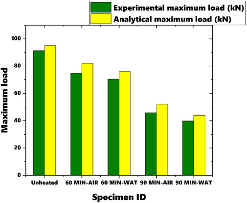
The comparison between the results obtained from FE analysis and experimental data, as shown in Figures 10, 11, showcased a remarkable level of concordance. Although some minor disparities surfaced between the FE predictions and experimental observations, they were negligible in magnitude. Numerical models were validated by comparing the ultimate loads obtained from the FE simulations (Figure 10) with those recorded in the experiments. This comparison showed a strong correlation, confirming the accuracy of the FE models in predicting the ultimate load-bearing capacity. Further validation was done by analyzing load-deflection curves derived from FE simulations (Figure 11). These curves were carefully analyzed to ensure that the FE models accurately captured the overall structural behavior, failure modes. This implies a strong correlation between the two datasets, affirming the reliability and precision of the FE models in simulating the behavior of MS-based CFS beam sections under varying temperature and cooling scenarios.
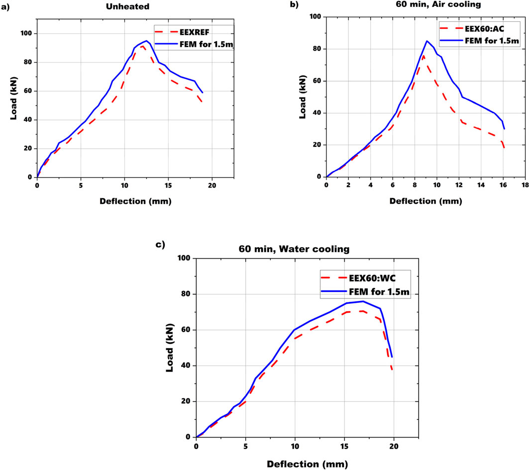
Figure 11. (A–C) Comparison of load deflection curves of 1.5 m long unheated and heated sections analyzed through experiment and FEM.
Geometrical imperfections were included in our FE models to accurately simulate the real-world behavior of the MS-based CFS beams. These imperfections are crucial for capturing the initial geometric imperfections and residual stresses that affect the structural performance under thermal and mechanical loads. Initial out-of-plane imperfections were modeled based on the first buckling mode shape obtained from a linear buckling analysis. The magnitude of these imperfections was set to a small fraction of the beam’s length. Residual stresses arising from the manufacturing process were considered in the material model. These stresses were introduced based on typical profiles observed in CFS sections. The inclusion of imperfections was validated by comparing the FE model results with experimental data. The load-deflection behavior, failure modes, and overall response of the beams in the FE models showed good agreement with the experimental observations, indicating that the imperfections were appropriately modeled.
4.5 Parametric analysis
Parametric analysis is done for sections with varying spans (3, 4.5, 6 m) to study the effect of span in flexural behavior of MS based CFS beams under elevated temperature. The flexural behavior of beams can significantly vary with changes in span length. Longer spans may exhibit different failure modes, stiffness, and load-carrying capacities compared to shorter spans. By studying various spans, a comprehensive understanding of these differences can be achieved. In practical applications, CFS beams are used in structures with varying span lengths. The findings from the parametric study provide valuable data that can inform design decisions, ensuring that the selected beam spans are optimized for both strength and ductility under fire conditions. The distribution of temperatures and the resulting thermal stresses can vary along the length of the beam. A parametric study helps in understanding how different spans influence these distributions and the subsequent structural performance. Dimensions of modelled built up beam sections are given in Figures 2–4. For beam sections of all lengths, distortional buckling emerged as the primary mode of failure. Remarkably, the buckling failure patterns and flexural responses observed in the FEM models closely mirrored those seen in the experimental counterparts. Figures 12A–C depict the failure modes for varying spans.
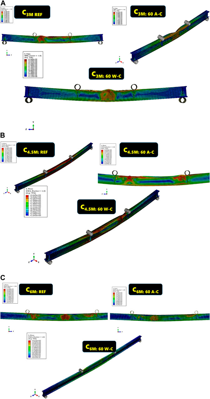
Figure 12. (A) Failure modes of beams with 3 m span, (B) Failure modes of beams with 4.5 m span, (C) Failure modes of beams with 6 m span.
These figures illustrate how the FEM models accurately capture the critical buckling modes and the corresponding structural responses, validating the efficacy of the modeling approach in representing the real-world behavior of the MS-based CFS beam sections under different loading and temperature conditions. The consistency between the experimental and numerical results underscores the reliability of the FEM analysis in predicting the performance and failure mechanisms of these beam sections. The failure modes captured through FEM analysis also matched with the failure modes noted through experiment and literature.
Loads obtained through experiment and FEM analysis were documented and compared with each other. Figures 13A–C depict load-deflection graphs obtained through FEM analysis for sections with varying spans. Similar to the experimental findings, these graphs show a reduction in load carrying capacity as the duration of heating increased.
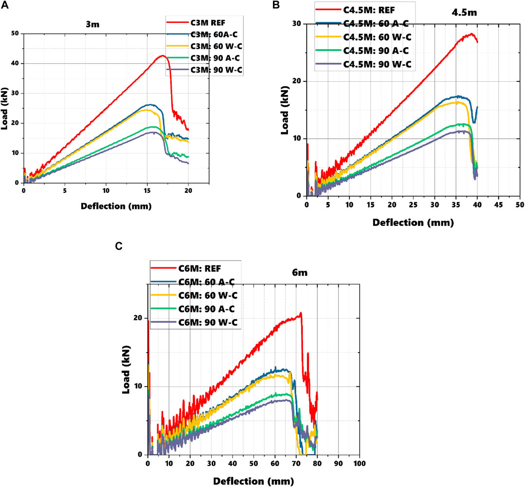
Figure 13. (A) Load deflection response of beams with 3 m span, (B) Load deflection response of beams with 4.5 m span, (C) Load deflection response of beams with 6 m span.
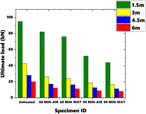
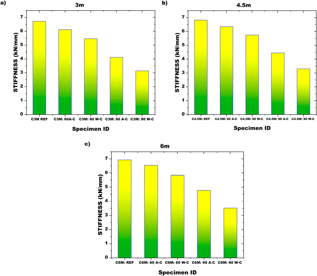
Figure 14 illustrates a comparison of all the loads obtained through experiment and FEM analysis. It is evident from the figure that as the span increases, the load carrying capacity decreases significantly. Among the unheated sections, comparing sections with lengths of 1.5 m and 6 m, the difference in load carrying capacity is noted to be 130.30%. Similarly, for sections heated for 60 min and cooled to room temperature using water, the difference between sections with lengths of 1.5 m and 6 m is 148.35%. Stiffness and ductility factors were calculated for all beams with different spans which were analyzed using FEM as shown in Figures 15, 16. In experiment analysis, stiffness was noted to decrease as the duration of heating was increased. Whereas ductility factor increased with increased durations of heating. To clarify further, the increase in ductility can be attributed to the relaxation of residual stresses and the alteration of material properties such as yield strength and stiffness. This phenomenon was consistently captured in the FEM analysis, which mirrored the experimental findings across various span lengths (3 m, 4.5 m, and 6 m) as seen in figure. The close correlation between the experimental data and the FEM results reinforces the reliability of the observed trend, validating that both methods accurately reflect the stiffness and ductility behavior of MS-based CFS beams under thermal stresses.
These comparisons highlight the impact of span length on the load carrying capacity of MS-based CFS beam sections under different heating and cooling scenarios. The consistency between experimental and FEM results reinforces the reliability of the numerical simulations in predicting the structural behavior and performance of these beams across varying conditions. The effective span of a CFS beam directly influences its flexural stiffness and strength. A longer span generally results in greater deflections and reduced stiffness due to the increased moment and shear forces experienced by the beam. This effect is particularly pronounced under high-temperature conditions, where the material properties of the CFS beam are altered, leading to decreased stiffness and strength. As the span length increases, the beam experiences higher bending moments and shear forces for the same load, leading to larger deformations and potentially reduced load-carrying capacity. This effect is exacerbated under elevated temperatures, as the reduced material strength further compromises the beam’s performance. Shorter spans typically result in lower bending moments and shear forces, leading to reduced deflections and potentially higher load-carrying capacity. However, the shorter span may also limit the beam’s ability to effectively distribute thermal stresses, impacting its performance under fire conditions. Longer beams are more prone to buckling due to the increased moment and reduced effective section modulus. Under high-temperature conditions, distortional and lateral-torsional buckling become more critical, as the reduced material strength exacerbates these failure modes. Longer spans may experience more significant thermal gradients, leading to uneven temperature distribution and increased residual stresses. This can contribute to differential expansion and contraction, potentially leading to warping or additional deformation. Shorter spans may exhibit more uniform temperature distribution, reducing the impact of thermal gradients and resulting in more predictable deformation patterns. By considering the impact of effective span on beam performance, engineers can optimize the design to balance between span length, load capacity, and fire resistance, ensuring that the beam performs adequately under expected conditions.
Table 5 provided below coefficient of variation calculated of ultimate load noted for all beam sections with various spans subjected to heating and cooling.
Although ABAQUS was employed with rigorous boundary conditions and material properties, FEM simulations inherently involve assumptions and simplifications. For instance, the material properties of cold-formed steel at elevated temperatures were modeled based on coupon test data, but real-world conditions may introduce more variability in these properties due to manufacturing inconsistencies or environmental factors not accounted for in the simulations. Moreover, the thermal and mechanical interactions in FEM simulations may not fully capture complex phenomena such as localized residual stresses, imperfections, or the exact nature of the temperature distribution across larger structures. These uncertainties could lead to slight deviations between the predicted results and real-world per While the study provides a comparison of the two cooling techniques, it is important to acknowledge that actual fire rescue operations may involve more complex cooling mechanisms, such as localized water jets or uneven cooling rates across different structural components. These uncertainties could lead to slight deviations between the predicted results and real-world performance, especially when considering fire scenarios with more heterogeneous thermal effects.
While the study provides a comparison of the two cooling techniques, it is important to acknowledge that actual fire rescue operations may involve more complex cooling mechanisms, such as localized water jets or uneven cooling rates across different structural components. This may lead to variations in the observed failure modes and load-bearing capacities in real-world applications.
The structural design employed in this study focused on back-to-back built-up channel beams. While this design is increasingly used in modern construction, other structural configurations such as single C-sections, Z-sections, or more complex built-up systems were not considered in this study. The behavior of these alternate designs under fire conditions may differ, and further research is required to generalize the conclusions drawn from this study to other CFS configurations.
4.6 Relationship
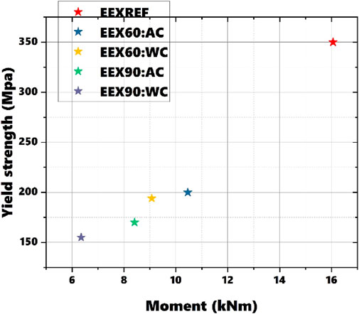
Figure 17 illustrates the relationship between yield strength and ultimate moment capacity derived from experimental loads under varying heating durations and cooling methods. The observed trend demonstrates that as yield strength decreases, the moment capacity of the structural elements also declines. This trend highlights a direct correlation between yield strength and the structural ability to resist bending moments. Prolonged exposure to high temperatures results in a reduction in yield strength due to thermal softening. As the material’s yield strength diminishes, it becomes less capable of sustaining bending loads, leading to a decrease in moment capacity. This is evident from the experimental data, where increased heating durations correspond to reduced moment capacities. The method of cooling—whether air or water—also affects the material’s residual yield strength and moment capacity. For instance, water cooling generally leads to more rapid temperature reduction and can induce different microstructural changes compared to air cooling. This difference in cooling methods results in varying levels of residual strength and moment capacity, as reflected in the results. High temperatures cause a reduction in yield strength due to thermal softening and material degradation. This loss of strength under thermal exposure directly influences the moment capacity of the structural elements, making them more prone to deformation and failure under applied loads. Understanding the effects of heating duration and cooling methods on yield strength and moment capacity is critical for structural design. These factors must be taken into account to ensure that structures maintain their integrity and performance under different thermal conditions.
5 DSM method
In this investigation, DSM was used to assess the design moment capacities of structural elements. Required section properties for this analysis are derived from coupon tests. By comparing the moments obtained through experimental tests and FEM simulations with those predicted by the DSM, this section provides a benchmark to ensure the reliability and accuracy of the experimental and computational findings. This comparison is essential for demonstrating that the observed behavior of the beams under thermal loading is consistent with standard design expectations, thereby reinforcing the credibility of the results. The primary purpose of this section is to validate the moments obtained from the experiments and FEM simulations against the moments calculated using the DSM. This validation is crucial because it helps confirm that the FEM models are accurately simulating the physical behavior of the beams, and that the experimental setup and results are sound. Furthermore, buckling analysis using specialized software CUFSM (CUFSM, 2018) using equations outlined in the (AISI, 2010) guidelines. For different durations of heating and cooling methods, material properties in CUFSM were modified to reflect the reduced material properties at the given temperature. By manually incorporating these thermal effects into CUFSM analysis, it was effectively simulated how elevated temperatures influence the buckling behavior of CFS sections. Table 6 showcases the moments obtained from experiments, FEM, and the DSM approach. Mean values and coefficient of variation are computed and presented in the table. It's noteworthy that moments calculated using FEM loads surpass those obtained through other methods. Conversely, the moments determined via the DSM method exhibit the lowest values among all approaches. Figure 18 depicts the signature curve derived through CUFSM for reference beam sections. These curves furnish invaluable insights into the thermal stress-induced behavior of the beam sections, enriching our comprehension of their performance.
The findings of this study hold significant relevance for the practical design of fire-resistant structures, particularly in scenarios where CFS members are utilized in building frameworks. One of the key applications of this research lies in the development of fire-safe structural systems for industrial and commercial buildings. Given the growing use of back-to-back built-up channel sections in CFS structures due to their cost-efficiency and ease of construction, understanding their behavior under thermal stress is critical for ensuring the safety of buildings during and after fire exposure.
The observed differences in load capacities between air-cooled and water-cooled specimens, along with the increase in ductility with heating duration, suggest that such CFS sections can maintain structural integrity even in the face of elevated temperatures. These insights are particularly applicable to the design of structures where fire safety is paramount, such as storage facilities, warehouses, and factories that house flammable materials, as well as multi-story buildings with long-span beams. Moreover, the study’s findings align with current building codes, particularly those addressing fire-resistant design in CFS structures. The parametric analysis provided in this study offers designers detailed data to evaluate the structural performance of CFS beams, taking into account varying spans and heating durations. In practice, the application of this research can lead to safer building designs by informing engineers about the expected failure modes—such as distortional buckling and lateral torsional buckling—under different thermal loading conditions. This knowledge is essential for designing CFS members in buildings located in regions with higher fire risks or where stringent fire safety regulations are enforced. Additionally, the findings can guide the selection of cooling methods post-fire, as water-cooled beams showed slightly lower load capacities compared to air-cooled beams, which may influence decisions during fire rescue operations and post-fire assessments.
By incorporating these findings into current fire design strategies, engineers can enhance the fire resistance of CFS structures, leading to safer and more resilient buildings that adhere to both safety standards and design efficiency.
6 Conclusion
This paper presents a comprehensive examination of MS-based CFS beam sections subjected to elevated temperatures and subsequently cooled using air or water. The beams were experimentally analyzed under two-point loading to investigate their flexural behavior. Experimental data were collected and validated through FEM.
Parametric studies were conducted on beams of three distinct lengths: 3 m, 4.5 m, and 6 m. Manual computations of the moments for these beams were performed using DSM, and the results were subjected to comparative analysis. The study aimed to provide insights into how MS-based CFS beams perform under thermal stress conditions and different cooling methods, using both experimental and numerical approaches to validate and analyze their flexural behavior.
• After testing, the specimens exhibited distortional buckling across all durations of heating. Specifically, buckling was noticeable on the stiffeners positioned beneath the loading points.
• Among beams heated to the same temperature, sections cooled with water show slightly lower loads compared to those cooled with air. The maximum load observed is 91.21 kN for the reference specimen, while the minimum load is 39.82 kN for the specimen heated for 90 min and cooled with water, resulting in a 78.45% difference between these values.
• The reference section exhibits the highest stiffness, while the section heated for 90 min and cooled using water shows the lowest stiffness, with a difference of 83.89% between these two values.
• For beam sections of all lengths, distortional buckling emerged as the primary mode of failure.
• Among the unheated sections, comparing sections with lengths of 1.5 m and 6 m, the difference in load carrying capacity is noted to be 130.30%. Similarly, for sections heated for 60 min and cooled to room temperature using water, the difference between sections with lengths of 1.5m and 6 m is 148.35%.
Data availability statement
The original contributions presented in the study are included in the article/supplementary material, further inquiries can be directed to the corresponding author.
Author contributions
VS: Data curation, Formal Analysis, Investigation, Writing–original draft. NA: Methodology, Supervision, Validation, Writing–review and editing. MiA: Funding acquisition, Validation, Writing–review and editing. CE: Funding acquisition, Validation, Writing–review and editing. MaA: Funding acquisition, Validation, Writing–review and editing. DA: Validation, Writing–review and editing.
Funding
The author(s) declare that no financial support was received for the research, authorship, and/or publication of this article.
Acknowledgments
The authors would like to thank Karunya Institute of Technology and Sciences to carry the work.
Conflict of interest
The authors declare that the research was conducted in the absence of any commercial or financial relationships that could be construed as a potential conflict of interest.
Publisher’s note
All claims expressed in this article are solely those of the authors and do not necessarily represent those of their affiliated organizations, or those of the publisher, the editors and the reviewers. Any product that may be evaluated in this article, or claim that may be made by its manufacturer, is not guaranteed or endorsed by the publisher.
References
AISI (2010). S100-07/S2-10, north American specification for the design of cold-formed steel structural members, supplement No.2. Iron Steel Inst. (2).
Aktepe, R., and Guldur Erkal, B. (2023). Experimental and numerical study on flexural behaviour of cold-formed steel hat-shaped beams with geometrical imperfections. J. Constr. Steel Res. 202, 107774. doi:10.1016/J.JCSR.2023.107774
Anbarasu, M., Dar, A. R., Rather, A. I., and Dar, M. A. (2021). Effect of external strengthening on the flexural capacity of cold-formed steel beams. Mater. Today Proc. 39, 1270–1274. doi:10.1016/j.matpr.2020.04.171
ISO 834-1 (1999). Fire-resistance tests - elements of building construction - Part 1: general requirements. ISO Stand. no. STD-615580.
Jaya Kumar, G., Kiran, T., Anand, N., and Al-Jabri, K. (2023a). Influence of fire-resistant coating on the physical characteristics and residual mechanical properties of E350 steel section exposed to elevated temperature. J. Struct. Fire Eng. 14 (2), 228–253. doi:10.1108/JSFE-02-2022-0008
Jaya kumar, G., Kiran, T., Anand, N., Anbarasu, M., and Lubloy, E. (2023b). Post-fire flexural behaviour and performance of unrestrained cold-formed steel built-up section beams: experimental and numerical investigation. Case Stud. Constr. Mater. 18 (March), e01978. doi:10.1016/j.cscm.2023.e01978
Karthik, C., Anbarasu, M., and Dar, M. A. (2022). Cold-formed ferritic stainless steel closed-section built-up beams: tests and flexural response. Thin-Walled Struct. 180, 109820. doi:10.1016/j.tws.2022.109820
Ma, R., Wang, X., Du, Y., Sun, G., Kang, S. B., Ma, J., et al. (2024). Experimental and theoretical investigation into flexural performance of thin-walled steel-laminated bamboo lumber truss beam. Thin-Walled Struct. 199, 111841. doi:10.1016/j.tws.2024.111841
Roy, K., Ho Lau, H., Ting, T. C. H., Chen, B., and Lim, J. B. P. (2021). Flexural behaviour of back-to-back built-up cold-formed steel channel beams: experiments and finite element modelling. Structures 29, 235–253. doi:10.1016/j.istruc.2020.10.052
Sabu Sam, V., Adarsh, M., Lyngdoh, G. R., Marak, G. W. K., Anand, N., Al-Jabri, K., et al. (2023). Influence of elevated temperature on buckling capacity of mild steel-based cold-formed steel column sections– experimental investigation and finite element modelling. J. Struct. Fire Eng. 15, 314–337. ahead-of-print, no. ahead-of-print. doi:10.1108/JSFE-08-2023-0033
Sabu Sam, V., Anand, N., Kumar, R., and Andrushia, D. (2024b). Influence of section profiles on flexural behavior of unsymmetrical cold formed steel sections – analytical and numerical investigation. J. Struct. Fire Eng. doi:10.1108/JSFE-05-2024-0009
Sabu Sam, V., N, A., K Marak, G. W., Lyngdoh, G. R., Alengaram, J., and Andrushia, D. (2024a). Investigation on residual mechanical properties of galvanized iron cold-formed steel sections exposed to elevated temperatures. Electron. J. Struct. Eng. 24 (1), 53–59. doi:10.56748/ejse.24439
Sam, V. S., Marak, G. W. K., Nammalvar, A., Andrushia, D., Gurupatham, B. G. A., and Roy, K. (2024b). Investigation on flexural behavior of galvanized cold-formed steel beams exposed to fire with different stiffener configurations. Fire 7 (9), 318. doi:10.3390/fire7090318
Sam, V. S., Nammalvar, A., Andrushia, D., Gurupatham, B. G. A., and Roy, K. (2024a). Flexural behavior of galvanized iron based cold-formed steel back-to-back built-up beams at elevated temperatures. Buildings 14 (8), 2456. doi:10.3390/buildings14082456
Sangeetha, P., Revathi, S. M., Sudhakar, V., Swarnavarshini, D., and Sweatha, S. (2021). Flexural behaviour of back-to-back built-up cold-formed steel channel beams: experiments and finite element modelling. Mater. Today Proc. 38, 3103–3109. doi:10.1016/J.MATPR.2020.09.492
Selvaraj, S., and Madhavan, M. (2019). Structural design of cold-formed steel face-to-face connected built-up beams using direct strength method. J. Constr. Steel Res. 160, 613–628. doi:10.1016/j.jcsr.2019.05.053
Yang, J., Luo, K., Wang, W., Shi, Y., and Li, H. (2024). Research on the flexural buckling behavior of the cold-formed steel back-to-back built-up columns with Σ-section. Eng. Struct. 302, 117404. doi:10.1016/j.engstruct.2023.117404
Yılmaz, Y., Öztürk, F., and Demir, S. (2024). Buckling behavior of cold-formed steel sigma and lipped channel section beam-columns: experimental and numerical investigation. J. Constr. Steel Res. 214, 108456. doi:10.1016/j.jcsr.2024.108456
Keywords: cold-formed steel, mild steel, flexural behavior, finite element analysis, direct strength method, built-up beam, elevated temperature, post fire
Citation: Sam VS, Anand N, Abdallah M, EI Hachem C, Azab M and Andrushia D (2024) Post fire flexural behavior of mild steel based cold-formed built-up beams exposed to elevated temperature. Front. Built Environ. 10:1466935. doi: 10.3389/fbuil.2024.1466935
Received: 18 July 2024; Accepted: 25 September 2024;
Published: 28 October 2024.
Edited by:
Mohammad Adil Dar, The University of Sheffield, United KingdomReviewed by:
Amir Ali Shahmansouri, Washington State University, United StatesSarmad Shakeel, The University of Sheffield, United Kingdom
Aamir Hassan, National Institute of Technology, Srinagar, India
Mohammad Zakir, Indian Institute of Technology Delhi, India
Copyright © 2024 Sam, Anand, Abdallah, EI Hachem, Azab and Andrushia. This is an open-access article distributed under the terms of the Creative Commons Attribution License (CC BY). The use, distribution or reproduction in other forums is permitted, provided the original author(s) and the copyright owner(s) are credited and that the original publication in this journal is cited, in accordance with accepted academic practice. No use, distribution or reproduction is permitted which does not comply with these terms.
*Correspondence: N. Anand, bmFuYW5kQGthcnVueWEuZWR1
 Varun Sabu Sam1
 N. Anand
 Marc Azab
