- Department of Civil and Environmental Engineering, Auckland Mail Centre, The University of Auckland, Auckland, New Zealand
Modular expansion joints (MEJs) are used for accommodating large relative displacements of adjacent bridge segments and for completely eliminating pounding. However, the minimum total gap that an MEJ needs to avoid pounding is not well investigated. To provide guidance for the seismic gap of MEJs, the maximum relative displacement of adjacent bridge segments subject to strong earthquakes was studied experimentally. To date, no experimental investigation of excitation spatial variation effect on bridge on natural soil has been reported. This research addressed a bridge with three identical segments of 100 m. A 1:22 scale bridge model founded on compacted beach sand was tested using electromagnetic inertial exciters. Different ground motions were applied to the model to simulate the effect of spatially varying ground motions. Soil–structure interaction (SSI) was studied by comparing the minimum total gaps with those obtained from the fixed-based experiments in the laboratory. The spatially varying ground motions were simulated based on the New Zealand design spectra for soft soil, shallow soil, and strong rock conditions using an empirical coherency loss function. SSI was found to reduce the minimum total gap of an MEJ needed to avoid pounding between adjacent segments. Under spatially varying ground motions designing adjacent bridge segments with identical or similar fundamental frequencies is still recommended even if it does not necessarily preclude an out-of-phase movement of adjacent structures.
Introduction
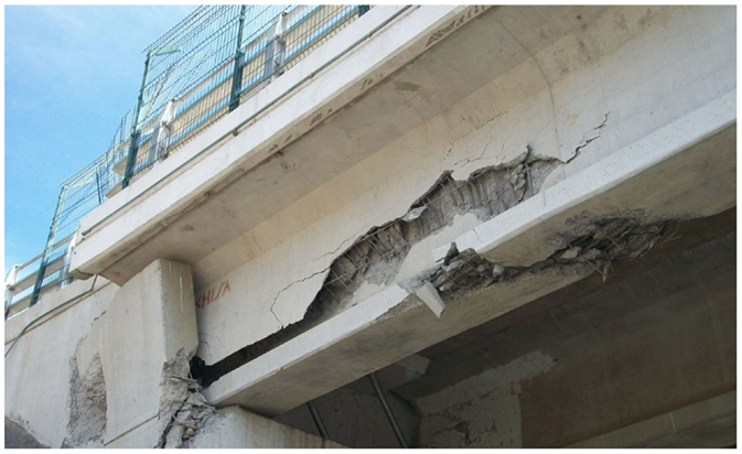
Observations from major earthquakes indicate that a long-span bridge is likely to suffer differential movement between adjacent segments that can lead to severe damage (see e.g., Figure 1). The reasons include dissimilar fundamental frequencies of the participating structural members, spatially varying ground motion, and soil–structure interaction (SSI) (Chouw and Hao, 2009; Raheem, 2009; Bi et al., 2010, 2011). Spatial variation of ground motion arises mainly from three sources, i.e., the wave passage effect arising from finite wave velocity, loss of coherency because of reflection, refraction, and superposition of the seismic waves and the site effect resulting from different local soil conditions (Kiureghian and Neuenhofer, 1992). Uniform ground motions are often assumed in seismic analyses. However, this is only justifiable for buildings or other structures of limited horizontal extension, under which the soil characteristics can, for simplicity, be assumed homogenous with negligible wave passage effect. For long structures such as bridges, the spatial variability of ground motions should be considered to avoid underestimation of relative displacements.
The establishment of the SMART-1 array (Strong Motion Array in Taiwan) (Bolt et al., 1982) sparked a substantial amount of research. Based on the SMART-1 recordings, Hao et al. (1989) proposed an empirical coherency loss function, which was recently improved by Bi and Hao (2012) to incorporate the capability of simulating spatially varying ground motions, which are design spectrum compatible. Discussion of the validity and limitations of some spatial coherency models was presented in the study of Zerva and Zervas (2002). Another study of Zerva (1990) revealed that the wave passage effect had a strong influence on flexible structures while the coherency loss effect was more critical to stiff structures. Dumanogluid and Soyluk (2003) studied a cable-stayed bridge subjected to spatially varying ground motions and found that local soil conditions can significantly affect the characteristics of seismic ground motions such as amplitude, frequency content, and duration of seismic waves. By investigating a multi-support bridge, Yang et al. (2002) concluded that the coherency loss and the local site effects were more pronounced than the wave passage effect. Research by Price and Eberhard (1998) found that not only long-span bridges but also short ones could suffer significantly from spatially varying ground motions.
To prevent unseating during an earthquake, minimum seating length was investigated by a number of researchers. Hao (1998) studied minimum seating length with respect to the bridge fundamental frequencies, span length, damping ratios, and spatially varying ground motions. It was found that the large seating length is needed when the fundamental frequencies of the bridge spans are within the dominant frequency range of the ground motion. Li et al. (2012) performed experiments on the relative girder displacements, considering a bridge with three identical segments. It was concluded that pounding increased the minimum seating length required to avoid unseating. Another research conducted by Li et al. (2013) on bridge pounding with abutments showed an increase in relative opening displacements between the girder and the abutment when spatially varying ground motions were considered.
Initially, to accommodate relative displacement due to thermal expansion and contraction, modular expansion joints (MEJs) were designed with several supporting bars to support a number of center beams perpendicular to the bridge longitudinal axis, dividing the total movement of a bridge gap into a number of small gaps without disturbing the traffic flow (Rizza, 1973). With a capacity to accommodate relative movements in excess of 2 m (Washington State Department of Transportation, 2011), their potential for seismic design has been confirmed by experimental research (Clyde and Whittaker, 2000; Spuler et al., 2011). Hao and Chouw (2007) identified the significant factors that influenced total minimum gaps of MEJs in seismic events, i.e., spatially varying ground motions, the fundamental frequency ratio of adjacent segments, and SSI. Chouw and Hao (2008) studied the SSI effect on the required separation distance of two adjacent bridge frames connected by an MEJ. They concluded that using an MEJ with a large total gap was likely to completely preclude girder pounding. Today, MEJs have been widely used throughout the world, e.g., Tsing Ma Bridge in Hongkong and Pont Canal de Beauharnois Bridge in Canada with maximum relative displacements of 2 and 1.52 m, respectively (Spuler and Gianni, 2004).
Very limited experimental studies involving shake table tests of multi-span bridges were reported. In addition to the studies (Li et al., 2012, 2013), Johnson et al. (2008) conducted an investigation on 1:4 scale, two-span reinforced concrete bridge model using three shake tables considering coherent ground motions in the transverse direction. Saiidi et al. (2007) studied the effect of bi-directional motions and interaction between a four-span bridge of 32 m and abutments on three shake tables and two actuators. Yang and Cheung (2011) shake table tested a 1:20 scale cable-stayed bridge considering the effect of non-uniform excitations. Wieser et al. (2012) at the University of Nevada, Reno investigated the seismic performance of seat-type abutments considering pounding with abutment using a 2:5 scale curved bridge model using four shake tables.
The previous studies on total gaps required for MEJs to avoid pounding were mainly based on numerical analyses. To the authors’ best knowledge, experimental investigations on the influence of SSI and spatial varying ground motion on MEJ total gaps have not been reported. The present study investigated the maximum relative girder displacements by field testing a 1:22 scale bridge model considering spatially varying ground motions. The use of a relatively large scale model and the execution of the tests in the natural environment (on a beach) gave more credibility to the test results. The research outcome helps to determine the minimum total gaps of MEJs between adjacent bridge girders. The experimental data without abutments are applicable to actual bridges because at all bridge joints, including abutment-girder joints, pounding should be avoided. Since with a well-designed MEJ pounding will not take place, there is no interaction between the girder and the abutment. Consequently, there is no carry over effect on the interior joints. Hence, an investigation without considering abutments is still valid for an MEJ between adjacent bridge girders.
Experimental Model and Ground Motions
Prototype Structure and Scale Model
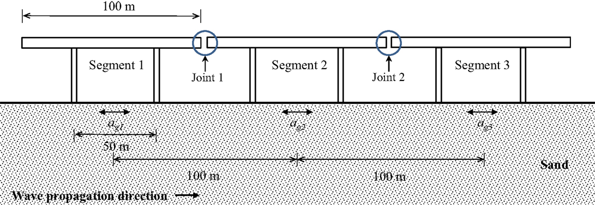
The scale bridge model was constructed based on a segment of the Newmarket viaduct replacement bridge in Auckland, New Zealand. The segment consists of a single-box girder with a length of 100 m and two bridge piers with a height of 15.5 m and a spacing of 50 m. To investigate the maximum relative girder displacement under spatially varying ground motions, a three-segment bridge without abutments was considered (Figure 2). It was assumed that each bridge segment experiences ground motions agn (t) acting at the middle of the segment along the span direction only, where n is the number of the sites considered (n = 1, 2, and 3).
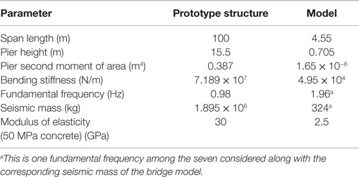
In order to model the prototype structure, the construction drawings of the Newmarket viaduct were used to determine the geometric and dynamic properties of the prototype structure from which the scale model was derived. In pursuit of the closest representation of the prototype, the fulfilment of the similitude requirements was attempted. By implementing Buckingham’s π theorem (Buckingham, 1914), the fundamental physical quantities, i.e., length, time, acceleration, stiffness, mass, and force were scaled. Each scaling ratio was determined mainly based on the nature of the testing conditions. A scaling approach proposed by Moncarz and Krawinkler (1981) was adopted. This approach suggests that the seismically effective mass of a structure can be decoupled from its structurally effective mass. The scale factors of the basic quantities are listed in Table 1. The parameters of the prototype structure and the experimental model are summarized in Table 2.
Polyvinylchloride (PVC) was selected to construct the model owing to its high strength-to-weight ratio and excellent workability. More importantly, the low modulus of elasticity of PVC, 2.5 GPa, led to a high mass scale ratio and hence a low model mass.
To achieve the appropriate model characteristics, the columns were fabricated as 100 mm × 36 mm box sections with a thickness of 6 mm and the deck was a 330 mm × 140 mm box section with a thickness of 10 mm. The dimensions of the model are shown in Figure 3. A pair of concrete foundations (pad footings) with dimensions of 340 mm × 340 mm × 70 mm was used.
Soil and Structural Properties and Test Setup
The field test was conducted on Auckland’s Kohimarama beach with the concrete footings founded on compacted sand with a depth of 200 mm. The compaction was performed with three sand layers to ensure that over a depth, the sand was uniformly compacted. The bridge was leveled. The in situ soil density was found to be 1.67 × 10³ kg/m3. The Rayleigh wave velocity was measured by two accelerometers positioned with spacing of 1 m. An electromagnetic inertia force exciter was used to apply harmonic loading, with a frequency band of 3.4–7.0 Hz, to the center of a round plate lying on the sand surface in line with the accelerometers. The selection of the frequency band is due to (1) that the phase velocity for frequencies lower than 3.4 Hz showed high uncertainty and (2) that the values of phase velocity for frequencies higher than 7.0 Hz may be affected by the higher modes of Rayleigh-waves (Tokeshi et al., 2008). The phase velocity of Rayleigh wave (vR) was estimated using Eq. 1 (Park et al., 1999):
where dx is the distance between the two accelerometers, and Δt is the difference in the arrival time of the waves to the accelerometers. The shear wave velocity (vs) can be approximated by Eq. 2:
where υ is the Poisson ratio of the soil. By assuming 0.33 for the Poisson ratio of the sand, the average shear wave velocity vs is found to be approximately 220 m/s.
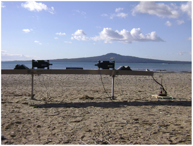
To apply excitations to the model bridge, two electromagnetic exciters (APS Model 400 Electro-Seis) were placed on the deck above the columns as shown in Figure 4. The exciters have a frequency range of 0–200 Hz, a peak stroke of 158 mm, and a mass of 73 kg. The excitations were the inertia force produced by the 18 kg attached masses driven by the exciters. The bridge deck displacements were recorded using a linear variable differential transformer (LVDT). Mass blocks (lead bar) each with a mass of 20 kg were used to achieve the seismic mass required. Figure 4 shows the model of the field experiment.
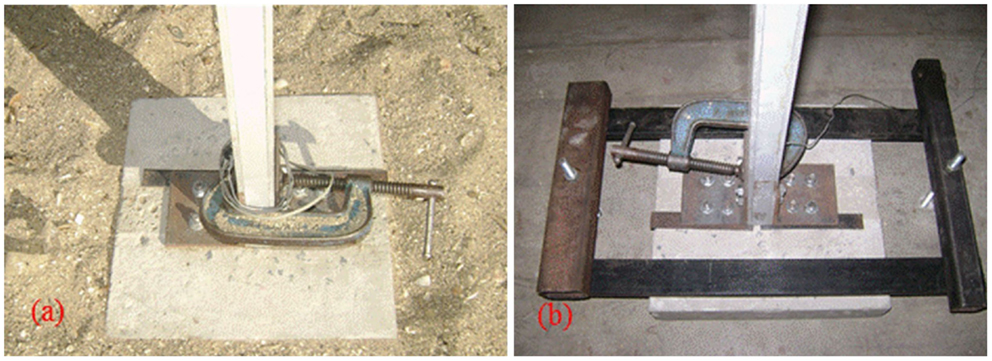
To understand the influence of SSI on the structural response, the same tests were conducted with a fixed-base foundation in the laboratory. For both foundation conditions, the columns were bolted to the concrete footings as shown in Figure 5.
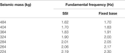
To incorporate a wide range of bridges, a series of segment fundamental frequencies were considered. The total mass of the blocks was varied to achieve the targeted fundamental frequencies between 1.7 and 2.3 Hz. Based on a time scale ratio of 1:2, these frequencies correspond to equivalent frequencies of 0.85–1.15 Hz for the prototype structure. This frequency range covers most bridge structures. By performing snap-back tests, the damping coefficients were found to range from 611 to 308 Ns/m and from 341 to 168 Ns/m, respectively, for the SSI cases and the fixed-base cases as the fundamental frequency of the bridge decreased from 2.19 to 1.62 Hz and from 2.3 to 1.7 Hz, respectively. The fundamental frequencies obtained from the free vibration fixed-base tests and field tests are summarized in Table 3.
Spatially Varying Excitation
The spatially varying ground motions were simulated based on an empirical coherency loss function (Bi and Hao, 2012), derived using more than 1000 strong ground motion time history records from the SMART-1 array. The spatially varying excitations were simulated based on the New Zealand design spectra (New Zealand Standards, 2004) with a spatial separation of 100 m. More details about the excitation development are provided by Li et al. (2012). Figure 6 shows the response spectra of the simulated excitation and the target design spectra.
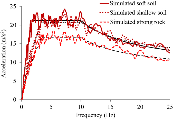
Figure 6. Response spectra of the simulated excitations (bold curves) and the target design spectra (thin curves) for three different soil conditions.
Results and Discussion
The applied spatially varying excitations were simulated based on the design spectra for soft soil (Class D), shallow soil (Class C), and strong rock (Class A) conditions. For the soft soil condition, high, intermediate, and weak correlations between the excitations at different supports were simulated while for the shallow soil and strong rock conditions, only high correlation of excitations was considered. To assure the generality of the results, for each soil condition and coherency loss, 20 sets of excitations were adopted, resulting in a total of 100 sets of spatially varying excitations. Since a controlled ground motion could not be applied to the underlying beach sand, the common approach was taken by applying horizontal acceleration with negative amplitude equal to the required ground acceleration. This has the effect of rendering the ground stationary and applying the true ground acceleration to the structural mass. The resulting inertia forces were generated by means of inertial force exciters, with the assumptions that:
1. The bases of each pair of piers as shown in Figure 3 are subject to the same ground motion.
2. The effective longitudinal structural mass is concentrated at the deck level, equally at the top of each pier.
3. There is no longitudinal structural interaction with adjacent segments at either end of the girder since the study focuses on the total gap required to avoid girder pounding.
4. Half the equivalent inertia forces are applied simultaneously to the deck at the tops of each pier (this is due to the limited capacity of the inertial exciters), and pier displacements are equal to those would result from direct ground excitation.
5. The model will behave as a SDOF system.
6. Only the influence of the characteristics of excitations of different soil conditions on the model response is considered while the same beach sand is used.
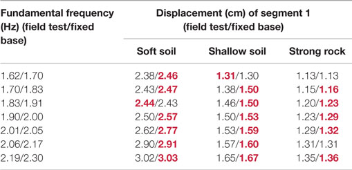
This study investigates the consequences of SSI and spatially varying excitations for the total gap that a MEJ must have to prevent pounding between bridge segments of variable fundamental frequencies. The relative displacements were normalized by the corresponding reference displacement, calculated as the average of the 20 maximum absolute girder displacements of segment 1 with an assumed fixed foundations due to excitations of the same soil condition. The reference values for each soil condition are given in Table 4. Larger displacements resulted from the soft soil condition than the shallow and strong rock conditions. This is due to the higher spectral values of the New Zealand design spectra for the soft soil condition in the vicinity of the fundamental frequency of the scaled model. By normalizing the relative displacements using the corresponding reference values, the effect of varying seismic input on the structure due to different soil types was neutralized. Hence, the results are comparable.
Some current bridge specifications, e.g., the California Department of Transportation (CALTRANS) (California Department of Transportation, 2010) and Japan Road Association (JRA) (Japan Road Association, 2004), advocate designing adjacent bridge spans to have the same or similar fundamental frequencies to reduce the likelihood of out-of-phase movement. However, even if all structural segments have the same fundamental frequency, if spatially varying excitations are present, relative girder displacements will consequently certainly occur.
Figure 7A compares the relative displacements (urel) of segments 1 and 2, both with a fundamental frequency of 1.9 Hz due to the spatially varying, time delayed and uniform excitations of the soft soil condition with SSI effects. For the spatially varying excitation, intermediate correlation was considered. The results show that the spatially varying excitation resulted in the largest relative displacements (the dotted line) while under the uniform excitation (the thick solid line) zero relative movement was expected as the bridge segments respond identically. It shows that the recommendation of matching fundamental frequencies of adjacent structures does not necessarily ensure in-phase motion. On the contrary, keeping the fundamental frequencies of the neighboring structures the same could cause out-of-phase response and hence relative displacements if spatial variation of excitations is anticipated.
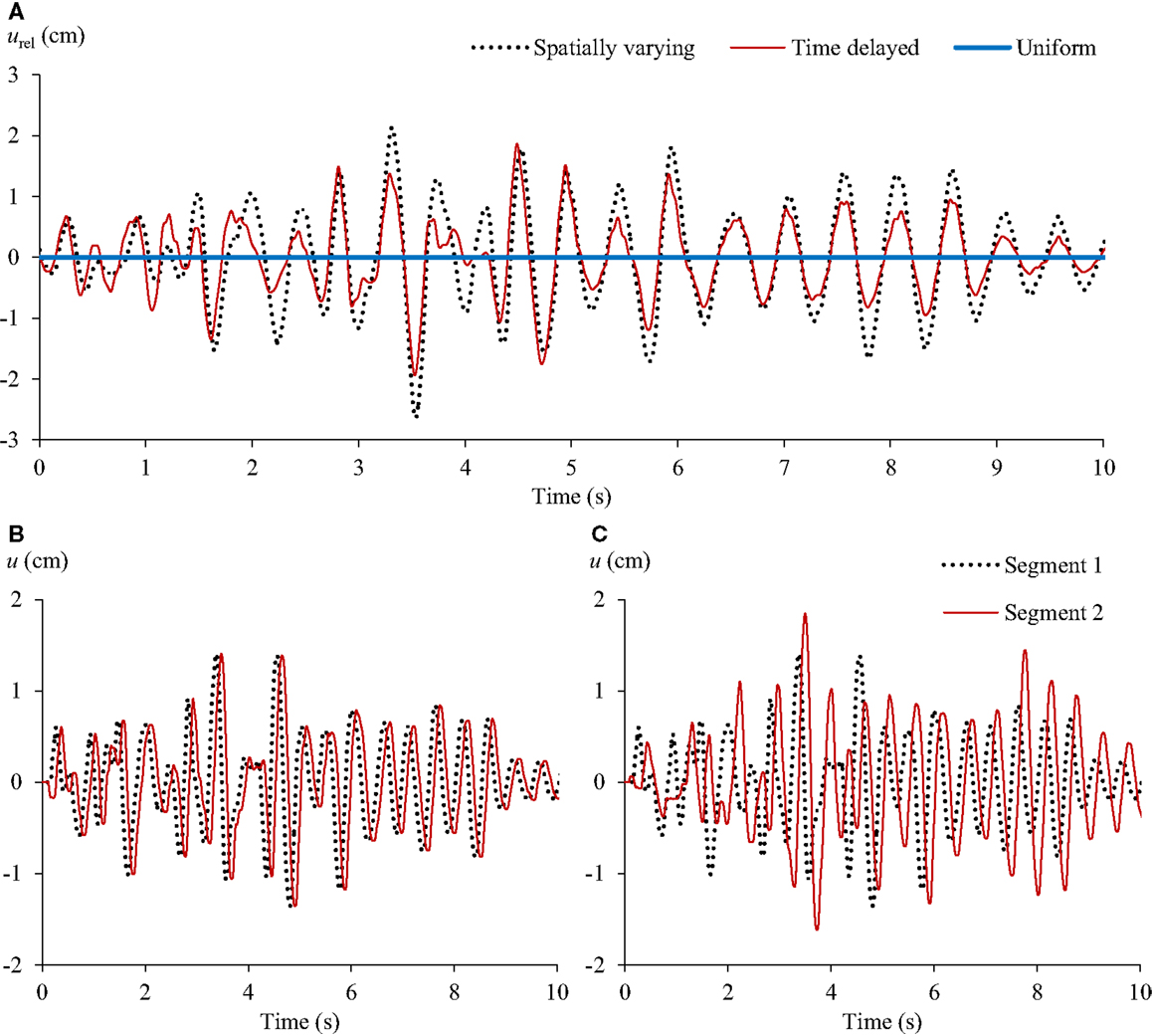
Figure 7. Time histories of (A) the relative displacements between segments 1 and 2, the absolute displacements of segments 1 and 2 due to (B) time delayed excitations and (C) spatially varying excitation with SSI.
It is observed from Figure 7A that the peak relative displacement (2.64 cm) due to the spatially varying excitation is larger than that (1.94 cm) resulting from the time delayed excitation. As seen in Figure 7B, with a site distance of 100 m and an apparent wave velocity of 500 m/s, the 0.1 s phase difference (due to a time scale factor of 1:2) is relatively small compared to the fundamental period of the bridge spans, i.e., 0.5 s, leading to smaller relative girder displacements compared to those due to the spatially varying excitation as shown in Figure 7C. Under the spatially varying excitation, because of coherency loss, the responses of segments 1 and 2 differed significantly, and hence resulted in larger relative displacements. The results indicate that spatial variation of ground motion should be given full consideration in the design of long-span bridges. Considering only the wave passage effect can underestimate the minimum total gap of an MEJ.
The normalized relative displacements due to different soil conditions and coherency loss were compared in Figure 8 for different fundamental frequency ratios (f2/f1 or f3/f2) due to SSI. When considering segments 1 and 2, the fundamental frequency of segment 1 was kept as 1.9 Hz and that of segment 2 was varied between 1.62and 2.19 Hz. For segments 2 and 3, segment 2 was kept with a fundamental frequency of 1.9 Hz. The reference displacements used to normalize the responses due to different soil conditions are provided in Table 4. Figures 8A,B reveal the consequences of different soil conditions of excitations for the relative girder response. For a frequency ratio of 0.85, the maximum normalized relative movement between segments 1 and 2 under the excitations of the soft soil condition was 1.6 while the minimum relative movement was no lower than 0.9, found in shallow soil condition at a frequency ratio of 1.08. For frequency ratios below 0.96, the excitations of the soft soil and strong rock conditions resulted in similar normalized relative displacements. According to Figures 8A,B, the soil conditions of the excitations have similar influence on the normalized relative response. In general, the relationship between the frequency ratio and the normalized relative displacements tends to be independent of the soil conditions of the ground motions.
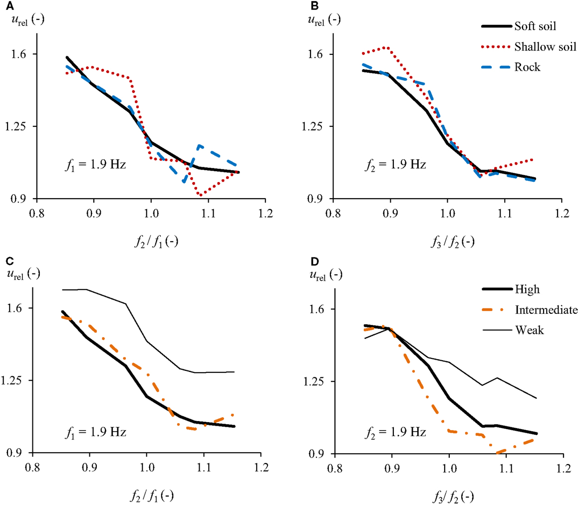
Figure 8. Normalized average maximum relative displacement between different segments (segments 1 and 2 or segments 2 and 3) considering SSI due to different (A,B) soil conditions of excitations with high correlation, and (C,D) coherency loss of excitations of soft soil condition.
Figures 8C,D show the influence of different coherency loss of excitations on the relative girder response. These figures indicate that the response of adjacent segments differed most when the corresponding site excitations had a weak correlation. For a frequency ratio of 0.85 between segments 1 and 2, the normalized average maximum relative displacement resulting from a weak excitation correlation was found to be 1.7, while high and intermediate correlations led to a normalized value of 1.6. When the frequency ratio was 1.15, the difference between the normalized average maximum relative displacements due to weak and intermediate correlations was approximately 0.2. These observations indicate that the consequences of having a weak correlation between the adjacent support excitations are more significant than having a high or intermediate correlation. If considering segments 2 and 3 (Figure 8D), the coherency loss effect of excitations became more pronounced as the relative response resulting from different coherency losses diverged more as the frequency ratio exceeded 0.9.
Since equalizing the fundamental frequencies of the adjacent structures cannot avoid out-of-phase movement in the presence of spatially varying excitations, it is important to determine the segment frequency combination that will result in minimum relative displacement even if spatial variability of excitations is considered.
In Figure 8, a descending trend in the normalized relative displacements can be clearly observed as the frequency ratio increases. Figure 9 reveals the reason for this descending trend with the plots of the relative and absolute girder displacements of segments 2 and 3 due to frequency ratios of 0.85 and 1.15, respectively. The maximum relative displacement resulting from each fundamental frequency ratio is indicated. As shown in Figure 9A, segment 3 responded to the excitation more vigorously between 3.7 and 5.5 s. During this period, the segments were almost moving in phase. The maximum relative displacement occurred at about 3.5 s, when the displacement of segment 2 almost reached its maximum while that of segment 3 was nearly 0. In contrast, Figure 9B shows that the displacements of segments 2 and 3 were, for most of the time, asynchronous. The maximum relative displacement took place when both segments approached the respective extreme absolute displacements in the opposite directions. It results in a maximum relative displacement of 4.45 cm, which is almost two times larger than that resulting from a frequency ratio of 1.15, i.e., 2.42 cm as shown in Figure 9A. This occurs even though the maximum displacement of segment 3 with a fundamental frequency of 2.19 Hz is larger than that with a fundamental frequency of 1.62 Hz.
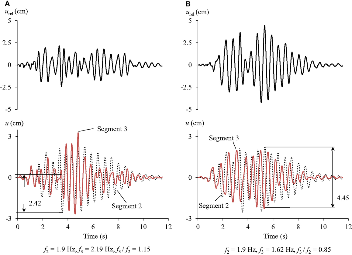
Figure 9. Consequence of frequency ratio for the relative displacements between segments 2 and 3 due to highly correlated excitations of soft soil condition for (A) f3/f2 = 1.15 and (B) f3/f2 = 0.85.
After examining the displacement time histories of segments 2 and 3 due to all the other spatially varying excitations, it was found for f3/f2 = 1.15 that most of the substantial displacements of the segment occurred between 4.5 and 6 s, during which, the segments responded almost in phase. For f3/f2 = 0.85 (Figure 9B), segments 2 and 3 moved completely out-of-phase at approximately 3 and 6 s, where the absolute displacements of segments 2 and 3 are significant. It is attributable to the unequal fundamental frequencies of the segments and the coherency loss of the excitations. The observation shows that the fundamental frequencies of the participating soil-footing-structure systems are important for determining the maximum relative displacements as they can contribute to the development of out-of-phase displacements of adjacent structures.
To study the effects of SSI, the average maximum absolute displacements of segment 1 due to SSI were compared with those due to fixed base in Table 5 for the excitations of different soil conditions. The larger girder displacement due to each foundation condition has been highlighted. It is clear that in most cases, SSI caused smaller maximum displacements than the fixed-base foundation for the same structural mass.
Figure 10 illustrates SSI effect on the normalized relative displacement between segments 1 and 2 and between segments 2 and 3 considering the wave propagating only from left to right. When considering segments 1 and 2, the fundamental frequency of segment 1 was kept as 1.9 Hz and that of segment 2 was varied between 1.62 and 2.19 Hz. For segments 2 and 3, segment 2 was kept with a fundamental frequency of 1.9 Hz. Note that the frequency ratios for the SSI cases and the fixed-base cases are similar but not the same. For the presentation, the frequency ratios for SSI case were used. The averages are shown in brackets. As observed from both figures, the majority of the differences are positive with the exception of some due to the soft soil condition for frequency ratios of 0.85, 1.06, and 1.08 in Figure 10A and 1.06 and 1.08 in Figure 10B with the negative differences insignificant compared to the positive ones. For the cases considered, SSI has a beneficial effect in terms of reducing the relative girder displacements. For segments 1 and 2, SSI reduced the relative displacements by a greater amount for the shallow soil and the strong rock conditions compared to the soft soil condition. The average reductions in the relative displacements for the shallow soil and strong rock conditions are 30 and 32% of the reference displacements i.e., 1.53 and 1.29 cm, respectively (see Table 4). In Figure 10B, the ground motions of shallow soil condition caused more reduction, i.e., 28% of the reference displacement on average, than the other soil conditions. SSI resulted in more reduction in the relative displacements between segments 1 and 2 than between segments 2 and 3 under the ground motions of the strong rock condition by comparing the average reduction in brackets (i.e., 0.32 and 0.10).
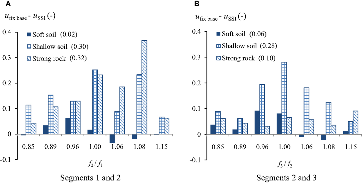
Figure 10. Differences between the normalized relative displacements between (A) segments 1 and 2 and (B) segments 2 and 3 with fixed-base foundation and with SSI due to spatially varying excitations.
In reality, the propagation direction of seismic waves is not predictable; however, it will affect the relative response of neighboring girders. In order to determine the maximum relative displacement between two segments, the seismic wave was considered to reach the three-segment bridge from either direction. In Figure 2, the case of seismic waves propagating from left to right is indicated. In the case of the excitations applied from the opposite direction, segment 3 would experience site 1 excitation [ag1 (t)] while segment 1 would experience site 3 excitation [ag3 (t)]. Figure 11 shows the minimum MEJ total gaps between segments 1 and 2 of the prototype bridge required to avoid pounding considering an earthquake loading in either direction. The fundamental frequency of segment 2 was varied while segment 1 was kept with a constant fundamental frequency of 1.9 Hz. The results in Figure 11 were obtained by selecting the larger values between the average maximum relative displacements resulting from the propagation of the seismic wave in either direction. This figure reveals that segments with an identical fundamental frequency required the smallest MEJ gap to prevent pounding. Consequently, even if spatially varying excitations can be anticipated, matching the fundamental frequencies of the adjacent girders is still beneficial as the bridge can experience the seismic wave from either direction. The soft soil condition required the largest minimum total gap while the strong rock condition demanded the least. When the frequency ratio changed from 1 to 1.15, the total gaps due to the ground motions associated with the soft soil condition increased by 0.34 m while the increase was only 0.12 m due to those of the strong rock condition. Thus, the influence of different fundamental frequencies of the segments on the total gap due to the ground motions of the strong rock condition was not as significant as for those of the soft soil condition.
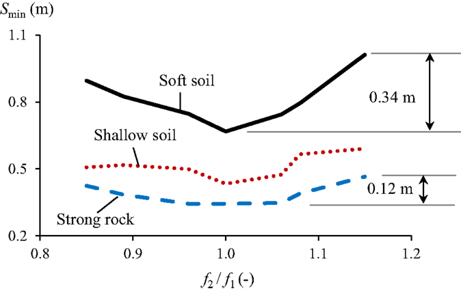
Figure 11. Minimum total gap required for an MEJ to avoid pounding between segments 1 and 2 due to highly correlated ground motions with SSI.
Figure 12 reveals the minimum MEJ total gap between segments 1 and 2 under the ground motions of different soil conditions considering the wave propagation in either direction. The fundamental frequency of segment 1 was kept as 1.9 Hz for SSI case and 2 Hz for fixed foundation case while those of segment 2 were varied. Figures 12B,D,F show the difference (Sspatial – Suniform) of the minimum total gap of structures with fixed foundation due to spatially varying and uniform ground motions and the difference (Sfixed – SSSI) between the minimum total gap of structures with fixed foundation and SSI due to spatially varying ground motions. As shown for all soil condition cases, the influence of spatially varying excitations on the minimum MEJ total gap is significant as the spatial variation, for almost all the frequency ratios, resulted in larger relative displacements than the uniform excitations.
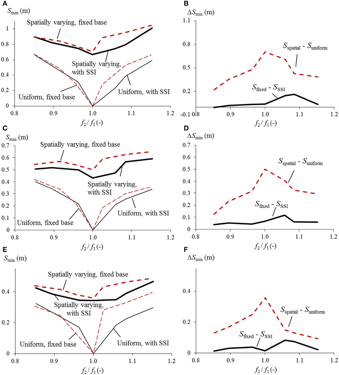
Figure 12. Consequence of spatially varying ground motion and SSI for the minimum total gap between segments 1 and 2 due to excitations of (A,B) soft soil, (C,D) shallow soil, and (E,F) strong rock conditions, all with high correlation.
When the segments have the same fundamental frequency, the underestimation of the total gap required to avoid pounding due to the assumption of uniform ground motions is most significant. Therefore, considering spatially varying ground motions is critical for bridge segments with identical fundamental frequencies. As the fundamental frequency ratio drifts away from 1, the underestimation of the MEJ gap due to neglecting spatial variation of ground motions becomes less. This is because the relative displacements due to the difference in the dynamic properties of the adjacent bridge segments also have a contribution to the total MEJ gap. The more different the adjacent bridge segments, the more dominant the influence of their dynamic properties, and the less the MEJ gaps is underestimated by neglecting spatially varying ground motions.
Soil–structure interaction reduced the minimum total gaps needed for preventing pounding as the difference between the total gap due to fixed base and SSI is always positive. The largest decrease of the minimum total gap due to SSI takes place when the frequency ratio is 1.08 in the case of soft soil condition and 1.05 in the case of shallow soil and strong rock conditions, equivalent to 19, 18, and 20% of the minimum total gap due to spatially varying ground motions of respectively the soft soil, shallow soil, and strong rock conditions with fixed-base foundation.
The minimum gap required for MEJs to avoid pounding can be displayed as a function of the fundamental periods of adjacent bridge segments in the form of a relative displacement spectrum (Chouw, 2016).
Conclusions
In contrast to conventional bridge expansion joints, MEJs can be used to prevent bridge pounding. To achieve this objective, the minimum total gap between the center beams should be at least equal to the maximum relative displacement between adjacent segments. To understand the simultaneous effects of spatially varying ground motions and SSI on relative girder displacement, a 1:22 scale bridge model was constructed and tested on beach sand using inertial force exciters. A range of fundamental frequencies was considered by varying the masses on the deck. Spatially varying excitations were modeled based on New Zealand design spectra with an empirical coherency loss function. The simulated excitations considered the soft soil, shallow soil, and strong rock conditions with the high correlation. In addition, for the soft soil condition, the intermediate and weak correlations were also considered. The tests were repeated with fixed foundations in order to compare with those obtained from considering SSI. A total of 4200 tests were performed.
Based on the results, the following conclusions are derived.
1. Since the excitation direction is unpredictable, the conventional bridge design recommendation of matching the fundamental frequencies of adjacent bridge structures can still be worth following as this will require the smallest total gap of an MEJ to prevent pounding even if spatially varying ground motions are considered.
2. Should the direction of the seismic wave propagation be given, making a bridge segment more flexible than the following segment can result in smaller relative girder displacements.
3. The combined effects of the wave passage and coherency loss can result in more than 30% larger relative girder displacements than considering the wave passage effect alone.
4. When SSI is considered, a weak correlation of spatial excitations may result in larger relative girder displacement than a high or an intermediate correlation.
5. In the cases considered, SSI is beneficial in terms of reducing the minimum total gap of an MEJ, even when spatially varying ground motions are considered. The reduction can be 20%.
6. An assumption of uniform ground motions for bridge segments with identical fundamental frequencies will underestimate the minimum gap significantly.
Author Contributions
BL: former PhD student, designed, performed the experiments, and analyzed the experimental data. NC: supervisor, provided the research question and the support in the discussion and interpretation of the research outcomes.
Conflict of Interest Statement
The authors declare that the research was conducted in the absence of any commercial or financial relationships that could be construed as a potential conflict of interest.
Acknowledgments
The authors would like to acknowledge the support of the Ministry of Business, Innovation and Employment through the Natural Hazards Research Platform under the Award UoA3701868.
References
Bi, K., and Hao, H. (2012). Modelling and simulation of spatially varying earthquake ground motions at sites with varying conditions. Probab. Eng. Mech. 29, 92–104. doi: 10.1016/j.probengmech.2011.09.002
Bi, K., Hao, H., and Chouw, N. (2010). Required separation distance between decks and at abutments of a bridge crossing a canyon site to avoid seismic pounding. Earthq. Eng. Struct. Dyn. 39, 303–323. doi:10.1002/eqe.943
Bi, K., Hao, H., and Chouw, N. (2011). Influence of ground motion spatial variation, site condition and SSI on the required separation distances of bridge structures to avoid seismic pounding. Earthq. Eng. Struct. Dyn. 40, 1027–1043. doi:10.1002/eqe.1076
Bolt, B. A., Loh, C. H., Penzien, J., Tsai, Y. B., and Yeh, Y. T. (1982). Preliminary Report on the SMART-1 Strong Motion Array in Taiwan. Report, No. UCB/EERC-82/13. Berkeley, CA: Earthquake Engineering Research Center, University of California at Berkeley.
Buckingham, E. (1914). On Physically Similar systems: Illustration of the Use of Dimensional Equations. Washington, USA: Bureau of Standards, The American Physical Society.
Chouw, N. (2016). “Dynamics of bridge structures,” in Innovative Bridge Design Handbook, ed. Pipinato A. (Amsterdam: Elsevier), 127–153.
Chouw, N., and Hao, H. (2008). Significance of SSI and non-uniform near-fault ground motions in bridge response II: effect on response with modular expansion joint. Eng. Struct. 30, 154–162. doi:10.1016/j.engstruct.2007.03.002
Chouw, N., and Hao, H. (2009). Seismic design of bridge structures with allowance for large relative girder movements to avoid pounding. Bull. N. Z. Soc. Earthq. Eng. 42(2), 75–85.
Clyde, D., and Whittaker, A. S. (2000). Full-Scale Dynamic Testing of Expansion Joints for Seismically Isolated Bridges. Report, No. EERCL/2000-01. Berkeley, CA: Pacific Earthquake Engineering Research Center, University of California at Berkeley.
Dumanogluid, A. A., and Soyluk, K. (2003). A stochastic analysis of long span structures subjected to spatially varying ground motions including the site-response effect. Eng. Struct. 25, 1301–1310. doi:10.1016/S0141-0296(03)00080-4
Hao, H. (1998). A parametric study of the required seating length for bridge decks during earthquake. Earthq. Eng. Struct. Dyn. 27, 97–103. doi:10.1002/(SICI)1096-9845(199801)27:1<91::AID-EQE722>3.0.CO;2-I
Hao, H., Oliveira, C. S., and Penzien, J. (1989). Multiple-station ground motion processing and simulation based on SMART-1 array data. Nucl. Eng. Des. 111, 293–310. doi:10.1016/0029-5493(89)90241-0
Hao, H., and Chouw, N. (2007). “Design of bridges with modular expansion joints for prevention of earthquake-induced girder poundings,” in The Australian Earthquake Engineering Society Conference. Wollongong, Australia.
Japan Road Association (JRA). (2004). Specifications for Highway Bridges-Part V Seismic Design, 5th Edn. Tokyo, Japan: Maruzen Co Ltd.
Johnson, N., Ranf, R. T., Saiidi, M. S., Sanders, D., and Eberhard, M. O. (2008). Seismic testing of a two-span reinforced concrete bridge. J. Bridge Eng. 13, 173–182. doi:10.1061/(ASCE)1084-0702(2008)13:2(173)
Kiureghian, A. D., and Neuenhofer, A. (1992). Response spectrum method for multi-support seismic excitations. Earthq. Eng. Struct. Dyn. 21, 713–740. doi:10.1002/eqe.4290210805
Li, B., Bi, K., Chouw, N., Butterworth, J. W., and Hao, H. (2012). Experimental investigation of spatially varying effect of ground motions on bridge pounding. Earthq. Eng. Struct. Dyn. 41, 1959–1976. doi:10.1002/eqe.2168
Li, B., Bi, K., Chouw, N., Butterworth, J. W., and Hao, H. (2013). Effect of abutment excitation on bridge pounding. Eng. Struct. 54, 57–68. doi:10.1016/j.engstruct.2013.03.034
Moncarz, P. D., and Krawinkler, H. (1981). Theory and Application of Experimental Model Analysis in Earthquake Engineering, Vol. 50. Stanford, USA: Stanford University.
New Zealand Standards. (2004). NZS 1170.5. Earthquake Actions. Wellington, New Zealand: Standards New Zealand.
Park, C. B., Miller, R. D., and Xia, J. (1999). Multi-channel analysis of surface waves (MASW). Geophysics 64, 800–808. doi:10.1190/1.1444590
Price, T. E., and Eberhard, M. O. (1998). Effects of spatially varying ground motions on short bridges. J. Struct. Eng. 124, 948–955. doi:10.1061/(ASCE)0733-9445(1998)124:8(948)
Raheem, S. E. A. (2009). Pounding mitigation and unseating prevention at expansion joints of isolated multi-span bridges. Eng. Struct. 31, 2345–2356. doi:10.1016/j.engstruct.2009.05.010
Saiidi, M., Vosooghi, A., and Nelson, R. (2013). Shake-table studies of a four-span reinforced concrete bridge. J. Struct. Eng. 139(8), 1352–1361. doi:10.1061/(ASCE)ST.1943-541X.0000790
Spuler, T., Ancich, E., Savioz, P., and O’Suilleabhain, C. (2011). “Developments in modular expansion joint technology-codes and testing in Australia, America and Europe,” in Proceedings of the 8th Austroads Bridge Conference. Sydney, Australia.
Spuler, T., and Gianni, M. (2004). Modular expansion joints for world’s largest bridges. IABSE Symp. Rep. 88, 30–35. doi:10.2749/222137804796302428
Tokeshi, K., Karkee, M., and Cuadra, C. (2008). Estimation of Vs profile using its natural frequency and Rayleigh-wave dispersion characteristics. Adv. Geosci. 14, 75–77. doi:10.5194/adgeo-14-75-2008
Washington State Department of Transportation. (2011). Bridge Design Manual. Available at: www.wsdot.wa.gov/publications/manuals
Wieser, J. D., Maragakis, E., Buckle, I. G., and Zaghi, A. E. (2012). “Experimental evaluation of seismic pounding at seat-type abutments of horizontally curved bridges,” in The 15th World Conference on Earthquake Engineering. Lisbon, Portugal.
California Department of Transportation (CALTRANS). (2010). Seismic Design Criteria. Design Manual Version 1.6. Sacramento, California, 1066 p.
Yang, C. Y., and Cheung, M. M. S. (2011). Shake table test of cable-stayed bridge subjected to non-uniform excitation. Procedia Eng. 14, 931–938. doi:10.1016/j.proeng.2011.07.117
Yang, Q., Saiidi, M. S., Hang, W., and Itani, A. (2002). Influence of earthquake ground motion incoherency on multi-support structures. Earthq. Eng. Eng. Vib. 1, 167–180. doi:10.1007/s11803-002-0063-4
Zerva, A. (1990). Response of multi-span beams to spatially incoherent seismic ground motions. Earthq. Eng. Struct. Dyn. 19, 819–832. doi:10.1002/eqe.4290190604
Keywords: field tests, spatial variation of ground motion, relative displacement, soil–structure interaction, minimum total gap of modular expansion joints
Citation: Li B and Chouw N (2016) Field Tests on Total Gap of Modular Expansion Joints to Avoid Bridge Pounding. Front. Built Environ. 2:7. doi: 10.3389/fbuil.2016.00007
Received: 23 November 2015; Accepted: 29 February 2016;
Published: 15 March 2016
Edited by:
Panagiotis Mergos, City University London, UKCopyright: © 2016 Li and Chouw. This is an open-access article distributed under the terms of the Creative Commons Attribution License (CC BY). The use, distribution or reproduction in other forums is permitted, provided the original author(s) or licensor are credited and that the original publication in this journal is cited, in accordance with accepted academic practice. No use, distribution or reproduction is permitted which does not comply with these terms.
*Correspondence: Nawawi Chouw, bi5jaG91d0BhdWNrbGFuZC5hYy5ueg==
 Bo Li
Bo Li Nawawi Chouw