ORIGINAL RESEARCH article

Front. Acoust. , 02 April 2025

Sec. Acoustic Metamaterials

Volume 3 - 2025 | https://doi.org/10.3389/facou.2025.1529474

This article is part of the Research Topic Acoustic Topological Insulators: Envisioned Applications and Technology Integration View all 3 articles

Inverse design of topological diatomic lattices based on complex phase locus

  • 1Department of Mechanical Engineering, Union College, Schenectady, NY, United States
  • 2Department of Mechanical Engineering, University of Vermont, Burlington, VT, United States
  • 3Department of Physics, University of Vermont, Burlington, VT, United States

Topological phononics and acoustics have recently garnered significant attention due to their promise of a wide range of advanced wave-controlling applications, including mechanical computing, energy harvesting, and noise isolation. Topological states are vibrational modes emerging inside frequency bandgaps, and typically follow the bulk-boundary correspondence, meaning that the topological features observed at boundaries are determined by the bulk properties—the unit cell. Traditionally, topological states are characterized by analyzing the eigenvectors of the effective Hamiltonian of a given unit cell. However, this approach presents challenges when a rapid and accurate design is needed to achieve desirable topological characteristics as it often involves trial and error to obtain the ideal unit cell parameters. In this study, we propose a rigorous methodology to inversely design one-dimensional diatomic lattices based on the topological properties of complex phase loci, derived from the off-diagonal elements of the effective Hamiltonian. We discuss three representative shapes of complex phase loci: ellipse, epitrochoid, and hypotrochoid. Our methodology can be further expanded to higher dimensions, enabling more complex geometric designs for versatile topological phononic and acoustic features.

1 Introduction

Topological insulators (TIs) are materials that possess intrinsic bandgaps while being conducive on non-trivial surfaces, edges, or corners (Haldane, 1988; Hasan and Kane, 2010) due to the emergence of topological states. The number of topological states can typically be characterized using a topological invariant derived from their bulk properties—a concept known as the “bulk-boundary correspondence.” Unlike trivial states, topological states of TIs are resilient to local perturbations and demonstrate high conductivity, making them promising for next-generation electronic and photonic devices (Qi and Zhang, 2011; Xu et al., 2017; Politano et al., 2017).

In recent years, research into acoustoelastic and phononic analogs of TIs has gained momentum due to their unique ability to control phononic waves in unconventional ways. These analogs are robust against disorders, exhibiting no backscattering (Roman and Sebastian, 2015; Nash et al., 2015; Ma et al., 2018; Pal et al., 2016; Fleury et al., 2016), allowing them to function effectively as phononic waveguides (Al Ba’ba’a et al., 2021; Wang et al., 2015; Ma et al., 2019; Mousavi et al., 2015), diodes (Liu et al., 2017; Zhou et al., 2020), logic gates and switches (Pirie et al., 2022; Bahrami and Bahrami, 2024; Li et al., 2024), and acoustic topological field-effect transistors (Lee et al., 2022). Meanwhile, the inverse design of acoustoelastic metamaterials to optimize topological states has also been proposed (Christiansen et al., 2019; Du et al., 2020; Ding et al., 2024). Like their electronic counterparts, phononic topological states also appear to adhere to the principle of bulk-boundary correspondence and can be characterized by a topological invariant derived from the spectral evolution of the mechanical equivalent of Hamiltonian or eigenvector obtained through unit-cell analysis. For instance, the mechanical analog of the Su–Schrieffer–Heeger (SSH) model consists of identical masses, m connected by springs with alternating spring constants k1 and k2 (Figure 1A). Such a mechanical system effectively yields an identical Hamiltonian to that of a typical SSH model. When k1k2, a bandgap opens in the dispersion diagram (Figure 1B) and a complex (closed-loop) phase function naturally emerges (Figure 1C). The topological invariant of such a case is represented by the winding number, ν, of the circular phase function in the complex plane around the plane’s origin (Asbóth et al., 2016). Systems with different winding numbers are rendered topologically distinct, and it has been commonly acknowledged that the difference in ν between two topologically distinct domains indicates the number of topological states at the domain boundary.
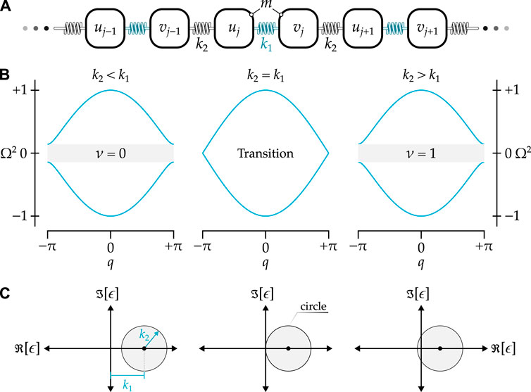
Figure 1
www.frontiersin.org

Figure 1. (A) Schematic of a diatomic lattice with a circular complex phase locus. (B) Typical dispersion diagrams with the cases of k2<k1, k2=k1, and k2>k1, corresponding to topologically trivial, transition (bandgap closing), and topologically non-trivial cases. Note that Ω=ωm/k, where k=k1+k2 in this case. (C) Complex phase loci ϵ projected on the complex plane for the three cases in subfigure (B).

However, recent studies have shown that systems with more complex connection networks, such as alternating non-local interactions in SSH models (Rajabpoor Alisepahi et al., 2023; Rajabpoor Alisepahi and Ma, 2024; Grundmann, 2020; Liu et al., 2023), can exhibit multiple domain boundary states due to a higher ν enabled by the presence of third-nearest neighbors. Additionally, the winding trajectories in these systems differ from the circular paths seen in the simple SSH model, which only considers nearest neighbors (Figure 1A). Instead, these phase loci exhibit interesting shapes with intricate internal loops. Moreover, contrary to common belief, the presence of non-local interactions means that details in the shapes of these phase loci—such as the Berry connection in one dimension (1D) (Rajabpoor Alisepahi et al., 2023; Cajić et al., 2024) and Berry phase in 2D (Dal Poggetto et al., 2024)—are crucial for determining the actual number of topological states between two domains with different ν values. This is more significant than merely considering the difference in the winding number ν (Rajabpoor Alisepahi et al., 2023; Cajić et al., 2024). These details truly reflect the actual number of domain boundary states, representing the phonon realization of the Jackiw–Rebbi modes—that is, the number of topological states is de facto determined by the number of Dirac points (Rajabpoor Alisepahi et al., 2023; Jackiw and Rebbi, 1976) —rather than by the winding numbers. Therefore, an analytical description of the detailed winding trajectories of these loci is essential for accurately characterizing the topology of systems with complex connection networks.

While it is now established that coupling beyond nearest neighbors in diatomic lattices uncovers new types of winding trajectories of the complex phase, controlling these trajectories and their overall shapes remains an open challenge. To address this knowledge gap, we propose a novel methodology that enables the selection of complex phase trajectories and facilitates the inverse design of a diatomic lattice exhibiting these intricate phase functions. We begin by revisiting the conventional diatomic lattice, characterized by a circular complex phase locus, and then discuss three representative locus shapes: ellipse, epitrochoid, and hypotrochoid. A step-by-step inverse design process is outlined for creating diatomic lattices that embody these complex loci. Furthermore, we establish connections between the mathematical features of these complex closed-loop locus geometries and the inversely designed diatomic lattices, analyzing their impact on the winding number through detailed parametric studies. By introducing this inverse-design methodology, our study lays the foundation for realizing wave-based acoustic and mechanical devices with complex and unconventional topological features, which are unattainable using simple lattices and structures.

2 Inverse design methodology

2.1 Revisiting the 1D Su–Schrieffer–Heeger model: the circular locus

To introduce our inverse design methodology for complex closed-loop locus geometries, we begin our discussion by revisiting the well-established simple 1D mechanical analog of the SSH model with identical masses, m, and alternating springs with stiffness parameters, k1 and k2 (Figure 1A). The governing dynamical equations describing the displacements (i.e., the first and second degrees of freedom uj and vj) of the two masses in unit cell j, the stiffness matrix of the mechanical system, and the corresponding dispersion relation can be found in Appendix A. The topological features are primarily represented by the chiral matrix, C(q), which is derived by eliminating the identical diagonal elements from the stiffness matrix (which is also the effective Hamiltonian) and is given

Cq=0ϵϵ0,(1)

where q is the wavenumber. The off-diagonal elements, ϵ and ϵ, are complex conjugates; ϵ will be the focus of our discussion now. Here, ϵ is referred to as the “complex phase locus,” which is a complex function of the wavenumber q and stiffness parameters k1 and k2; it is expressed as,

ϵ=k1+k2eiq.(2)

As detailed in Appendix A, the eigenvalues of C(q), denoted as λ, can then be solved as:

λ=±|ϵ|/m.(3)

Results of the normalized eigenvalues Ω2=mλ/k (with k=k1+k2) for q[π,π] and different relationships between k1 and k2 are presented in Figure 1B.

We now focus on how ϵ dictates the topology of the diatomic lattice. If ϵ in Equation 2 is depicted in the complex plane for a complete cycle of the wavenumber q[0,2π], the result is a perfect circle with a radius of k2 and a center shifted horizontally by k1 from the origin. This can be easily proven by transforming the expression ϵ into the form:

ϵ=x+iy,(4)

with x=R(ϵ) (y=I(ϵ)) being the real (imaginary) part of ϵ. Using Equations 2, 4, the x and y values can be shown as:

x=k1+k2cosq,(5a)
y=k2sinq,(5b)

once again, representing a circle with the radius being k2 as shown in Equations 5a, b and the parametric variable (or angle) being q. The shift of the circle’s center in the x-direction is also evident by the addition of k1 in Equation 5a. As shown in Figure 1C, the center of the circle is at the coordinates (k1,0), located on the positive real axis, since k1>0 is required for dynamical stability (k2>0 is also enforced for the same reasoning). From the figure, we can count the number of times the locus ϵ winds about the origin of the complex plane—the winding number, ν—which characterizes the topological domain-boundary states of this simple SSH lattice. Such a winding number can be equivalently computed using the following integral:

ν=ππBqdq,(6)

where B(q) is the Berry connection, defined as per Chiu et al. (2016):

Bq=14πitrσ3C1qC.(7)

Here, σ3 denotes the third Pauli matrix and tr[] represents the matrix trace.

For the conventional diatomic lattice, where the complex phase locus is given by Equation 2, the Berry connection can be derived analytically. This involves evaluating the inverse and the q-derivative of the chiral matrix C(q) in Equation 1 and substituting them into Equation 7. The resulting expression for the Berry connection is as follows:

Bq=k2k2+k1cosq2πk12+k22+2k1k2cosq.(8)

By performing the integral in Equation 6 for the Berry connection (i.e., the integrand) in Equation 8 using MATLAB’s symbolic toolbox, we obtain the winding number:

ν=121sgnk1k2k1+k2.(9)

The topological invariant—the winding number μ as expressed in Equation 9—can thus be summarized as follows:

ν=1k2>k10k2<k1(10)

As observed from Figures 1B, C, if k1<k2, the locus ϵ will wind the origin once, ν=1, suggesting the choice of the unit cell being topological and vice versa.

In the following sections, we will inversely design diatomic lattices with complex networks based on the shape of ϵ given by the relationship between x and y in Equation 4. Three examples of complex phase loci will be presented to demonstrate how to design a mechanical network system to achieve desired topological characteristics.

2.2 Ellipse

In this section, the inverse design methodology for a diatomic lattice based on an elliptical complex phase locus is detailed. Herein, the masses, m, of the inverse-designed lattices are assumed to be constant throughout this study, and emphasis is placed on the spring interconnections. Using Equation 4, the parametric form the x and y coordinates for an ellipse, with its center being on the positive real axis, are given by:

x=k1+k2cosq,(11a)
y=k3sinq.(11b)

Here, k1 shifts the center of the ellipse from the origin of the complex plane, similar to its role in Equation 5a for a circular locus. The parameters k2 and k3 define the semi-major and semi-minor axes of the ellipse, respectively. Substituting Equations 11a, 11b into Equation 4, we obtain the following:

ϵ=k1+k2+k32eiq+k2k32eiq.(12)

Notice that Equation 12 reduces to Equation 2 when k2=k3, as a circle is a special case of an ellipse. The parameters k1, k2, and k3 not only define the geometry of the ellipse but also determine the properties of the springs interconnecting the diatomic lattice.

To inversely design a lattice from the complex phase locus expressed in Equation 12, we need to understand the roles of each term constituting ϵ in conjunction with the Bloch theorem. Recall that the terms ϵ and ϵ are the off-diagonal elements in the chiral matrix C in Equation 1, which describes the coupling between the unit cell’s degrees of freedom. For instance, ϵ represents the coupling between the second degree of freedom in the current unit cell vj and the first degree of freedom uj. The latter can be in the current cell or any other cell, expressed through the term e±iq. Similarly, ϵ couples the first degree of freedom to the second in any cell.

Thus, we can establish the interconnecting network between the two degrees of freedom based on the following three characteristics of Equation 12:

• Characteristic 1: The term k1 couples the two degrees of freedom within the current unit cell j, i.e., uj and vj, as it is independent of the wavenumber q.

• Characteristic 2: The second term, (k2+k3)/2, is multiplied by eiq, indicating that the second degree of freedom in cell j, i.e., vj, is coupled with the first degree of freedom in the next cell, j+1, expressed as uj+1=ujeiq per the Bloch theorem, through a spring constant (k2+k3)/2.

• Characteristic 3: The third term, (k2k3)/2, is multiplied by eiq, suggesting that vj is connected with the first degree of freedom in the previous cell, j1, i.e., uj1=ujeiq, through a spring constant of (k2k3)/2, which requires a beyond-nearest-neighbor connection. To ensure dynamical stability, k3<k2 must be enforced.

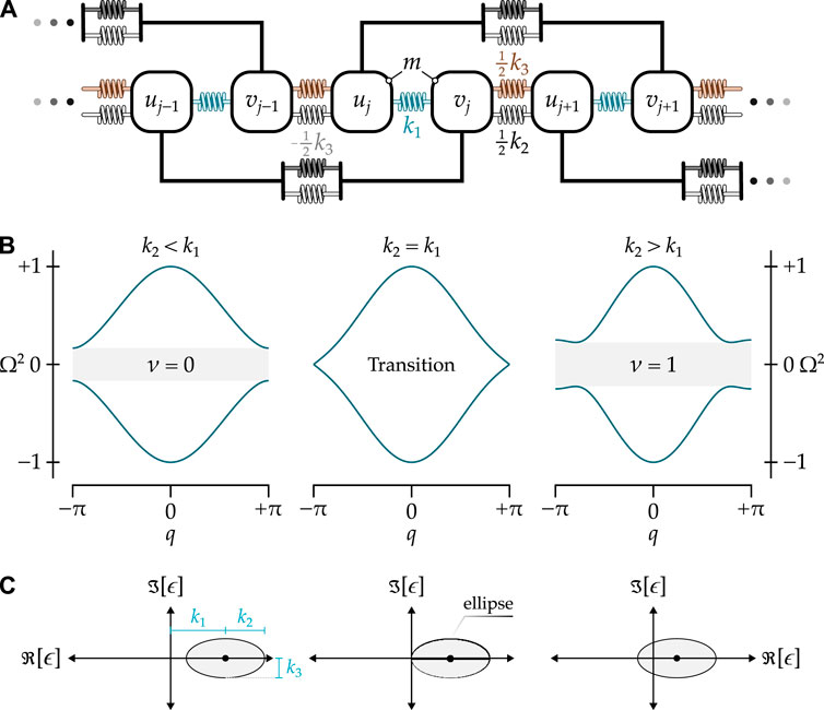
Based on these three characteristics, the degrees of freedom are connected as described, resulting in the diatomic lattice in Figure 2A, with the unit-cell equations of motion being:
müj+k1+k2ujk1vjk2+k32vj1k2k32vj+1=0,(13a)
mv̈j+k1+k2vjk1ujk2k32uj1k2+k32uj+1=0.(13b)

Figure 2
www.frontiersin.org

Figure 2. (A) Schematic of a diatomic lattice with a complex phase locus of an ellipse. (B) Dispersion diagrams of the lattice in Subfigure (A) with a constant k3 and k2<k1, k2=k1, and k2>k1. Note that Ω2=mλ/k, where k=k1+k2 in this case. (C) Complex phase loci ϵ projected on the complex plane for the three cases in subfigure (B). Analogous to the diatomic lattice with nearest neighbor interactions only (Figure 1), the lattice is topologically non-trivial only if the locus (the ellipse in this case) winds the origin once (ν=1), which happens if k2>k1.

We can observe that if the degrees of freedom in Equations 13a, b are condensed via the Bloch theorem, the resulting stiffness matrix will have constant diagonal elements of k=k1+k2 despite the introduction of a new spring constant k3. Interestingly, the diagonal elements of the stiffness matrix for the diatomic lattice in Figure 2A are identical to those of a conventional diatomic lattice (Figure 1A) without next-nearest-neighbor connections, (see Appendix A). This similarity arises from the cancellation of the equal magnitude but opposite sign stiffnesses k3/2 from the nearest and next-nearest couplings.

To reveal the topological properties of the diatomic lattice with an elliptical phase locus in Figure 2A, the winding number is calculated by performing the integral in Equation 6 for the chiral matrix C in Equation 1 with ϵ defined in Equations 11a, b. This process yields a closed-form expression for the winding number:

ν=121sgnk1k2k3.(14)

As with the conventional diatomic lattice with a circular locus in Figure 1C, the winding number is defined via Equation 14, indicating that it only depends on k1 and k2, provided that k3>0 to ensure dynamical stability. Figures 2B, C illustrate the dispersion relation and the corresponding complex phase loci, respectively, for three cases: (i) topologically trivial k2<k1, (ii) topological transition k2=k1 with the sole bandgap closed, and (iii) topologically nontrivial k2>k1. The last case can be inferred by the winding of the ellipse around the origin of the complex plane (i.e., ν=1 as indicated by Equation 10), which is clearly seen in the right-most panel of Figure 2C.

2.3 Epitrochoid

Next, we shift our focus to a more complex family of loci known as epitrochoids, whose general form is depicted in Figure 3A. Epitrochoids are closed-loop roulettes generated by tracing a point fixed at a distance k4 (initially pointing to the negative real axis) from the center of a circle with radius k3. Termed the “epicycle,” this circle rolls counterclockwise without slipping around the outside surface of a stationary circle of radius k2, completing a closed loop. The stationary circle is assumed to have its center on the positive real axis, with a horizontal distance of k1 from the origin of the complex plane. Here, we define an integer n that takes a value greater than 2; its relationship to the inversely-designed lattice will be explained shortly. Additionally, depending on the epitrochoid parameters, this integer n determines the number of internal loops the epitrochoid may exhibit—specifically n1 internal loops.
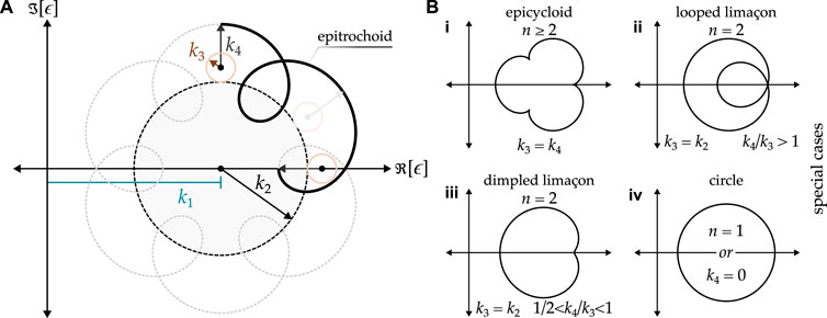
Figure 3
www.frontiersin.org

Figure 3. (A) Complex phase locus of an epitrochoid shape, shown for n=7, resulting in n1 internal loops; its geometrical properties are related to the stiffness parameters in the diatomic lattice (Figure 4). (B) Multiple special cases of the epitrochoid shown for reference, along with their respective parameters, including (i) epicycloid, (ii) looped limaçon, (iii) dimpled limaçon, and (iv) circle.

From the general epitrochoid locus, various special cases can be derived by selecting different sets of parameters. For instance, when k3=k4 and n2, we obtain epicycloids (Figure 3Bi). When k3=k2 and n=2, we obtain a limaçon (also known as “Pascal’s snail”), similar to the system briefly discussed by Chen et al. (2018). For the latter, a looped limaçon (Figure 3Bii) occurs when k4/k3>1, transitioning to a non-looped limaçon when k4/k3=1, at which point the curves take the shape of an epicycloid with a single cusp (often called a “cardioid”). When 1/2<k4/k3<1, the limaçon curve loses its inner loop and features a dimple instead (Figure 3Biii). Further reduction of the ratio below one-half smooths out the curve to a convex limaçon until k4 approaches 0, at which point the limaçon converges to a circle (Figure 3Biv). Note that n=1 also results in a circle of radius k2+k3k4, which is not of interest in this work. As discussed next, the parameters k1 through k4 will be related to the spring constants of a diatomic lattice via the inverse design methodology.

Again, the inverse design of a diatomic lattice with an epitrochoid complex phase locus starts by explicitly stating x and y parametric expressions in Equation 4 for an epitrochoid, which are given by:

x=k1+k2+k3cosqk4cosk2k3+1q,(15a)
y=k2+k3sinqk4sink2k3+1q.(15b)

To construct the complex phase locus ϵ with the epitrochoid roulette, the factor multiplied by the wavenumber in the cosine/sine arguments in Equations 15a, b must be an integer n. Therefore, k2/k3+1=n, mandating that k2=(n1)k3. Thus, the parametric equations in (Equations 15a, b) reduce to:

x=k1+nk3cosqk4cosnq,(16a)
y=nk3sinqk4sinnq.(16b)

Substituting Equations 16a, b back into Equation 4 provides the expression of ϵ as:

ϵ=k1+nk3eiqk4einq.(17)

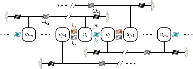
Following the methodology presented in Section 2.2, the diatomic lattice corresponding to the complex phase locus in Equation 17 is shown in Figure 4. Note that due to the negative stiffness k4 coupling (as implied by Equation 17), an elastic foundation must be implemented to prevent dynamical instability. Consequently, adding an elastic foundation stiffness equal to twice k4 is recommended. This adjustment results in the following equations of motion for the unit cell:
müj+k1+k2+k3+k4ujk1vjk2+k3vj1+k4vjn=0,(18a)
mv̈j+k1+k2+k3+k4vjk1ujk2+k3uj+1+k4uj+n=0.(18b)

Figure 4
www.frontiersin.org

Figure 4. Schematic of a diatomic lattice with coupling beyond next neighbors, resulting in a complex phase locus of epitrochoid shape.

After utilizing k2+k3=nk3, Equations 18a, b become

müj+k1+nk3+k4ujk1vjnk3vj1+k4vjn=0,(19a)
mv̈j+k1+nk3+k4vjk1ujnk3uj+1+k4uj+n=0.(19b)

The topology of the diatomic lattice with an epitrochoid locus depends on the choice of the three stiffness parameters k1, k3, and k4, as k2 and k3 are dependent (as discussed above). Since k1+nk3+k4 in Equations 19a, b represents the sum of the spring constants connected to each mass in the lattice and remains constant, we define this spring constant as k=k1+nk3+k4. Recall that the integer n denotes the connection between one of the degrees of freedom in the current cell j and its counterpart in the (jn)th cell. Therefore, the choice of k1, k3, and k4 is constrained by a given set of k and n.

As illustrated in Figure 3, the parameter k1 determines the center position of the complex locus, while k2=(n1)k3 governs the size of the main loop. The stiffnesses k3 and k4 control the size of the epitrochoid’s internal loops, if present. When the internal loops are much smaller than the main loop (i.e., when k4k3), the system exhibits only two possible winding numbers: 0 and +1, depending on whether k2+k3=nk3 is smaller or greater than k1. This behavior aligns with that of a simple SSH model with weak or negligible non-local interactions. As the non-local spring constant k4 increases, the internal loops grow in size and begin to wind around the origin counter-clockwise. The winding number then assumes positive odd or even integers when n is even or odd, respectively. This phenomenon can be attributed to the symmetry of the locus about the real axis. When k4nk3 and k1 is relatively small, the size of the internal loops approaches that of the main loop, resulting in the maximum possible winding number, equal to n. A summary of possible winding numbers for an epitrochoid complex locus is shown in Table 1, and examples of winding numbers for various cases of n are provided in Appendix B.

Table 1
www.frontiersin.org

Table 1. Summary of possible winding numbers for an epitrochoid complex locus.

Additionally, it is important to note that the maximum number of Dirac points in the first Brillouin zone, corresponding to the number of band crossings when the bandgap is closed, is n. This corresponds to the difference between the maximum and minimum values of ν. This observation aligns with the phonon realization of the Jackiw–Rebbi theory (Jackiw and Rebbi, 1976) in lattices with non-local interactions, as discussed by Rajabpoor Alisepahi et al. (2023).

For example, consider the case of n=5. Here, five distinct topological states are observed, corresponding to winding numbers of ν=0,1,2,4,and5, as depicted in the barycentric triangle in Figure 5. When the combination of these stiffness parameters varies along the transition boundaries between regions of different winding numbers, the bandgap closes when |ϵ|=0, indicating topological transitions. Note that the numerical procedures for calculating μ follows Pal et al. (2018).

Figure 5
www.frontiersin.org

Figure 5. Barycentric triangles, showing the winding numbers (left) and bandgap width (right) for n=5 and swept values k1, k3, and k4, such that k=k1+nk3+k4, for a diatomic lattice with epitrochoid complex locus. Five distinct regions are obtained, each of which corresponds to a specific winding number, ν, with the boundaries in-between representing the transitional states when the bandgap closes, occuring at |ϵ|=0. Note that the sole bandgap significantly grows in size when approaching the corners of the Barycentric triangles, i.e., k1k, nk3k, or k4k.

It is worth noting that the bandgap’s width increases significantly near the corners of the Barycentric triangle, which correspond to the cases k1k, nk3k, or k4k (Figure 5). This behavior arises because the bandgap width is strongly influenced by the degree of space inversion symmetry (SIS) breaking within a unit cell. Near the corners of the Barycentric triangle, SIS is significantly disrupted due to large disparities between the nearest neighbors (near the top two corners) and the beyond-nearest neighbors (near the bottom corner). At the center of the triangle, where the strengths of k1, nk3, and k4 are comparable, the symmetry-breaking effects of nearest and beyond-nearest neighbors compete. This competition leads to intermediate values of the winding number ν and weakens the overall symmetry-breaking effect, resulting in a narrower bandgap. Therefore, the area of each ν in the barycentric triangle does not directly correlate with the bandgap width. Instead, the bandgap width is determined by the specific combination of k1, nk3, and k4, which governs the extent of SIS breaking.

To highlight the difference between the topologically distinct regions, five representative combinations of stiffness parameters are selected and listed in Table 2. Their corresponding dispersion relations, calculated using Equation 3 in conjunction with Equation 17, as well as their complex phase loci, are presented in Figure 6.
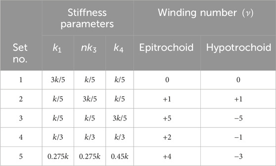
Table 2
www.frontiersin.org

Table 2. Selected combinations of stiffness parameters and their corresponding winding numbers for the lattices with epitrochoid and hypotrochoid complex phase loci, shown in Figures 6 and 10, respectively. Note that n=5 and k=k1+nk3+k4 are satisfied for all cases.

Figure 6
www.frontiersin.org

Figure 6. Dispersion relations and complex phase loci of five distinct topological states of epitrochoid diatomic lattices obtained by varying stiffness parameters k1, k3, and k4 with the constraint of k=k1+nk3+k4 when n = 5 Choices of k1, k3, and k4 corresponding to each ν are summarized in Table 2. Note that ϵ is normalized with respect to k.

2.4 Hypotrochoid

This section explores complex phase loci in the shape of hypotrochoids. These closed-loop roulettes are generated like the epitrochoids discussed in Section 2.3, with the definitions of parameters k1 through k4 remaining unchanged (Figure 7A). However, there are two key differences in terms of the rotation of the epicycle: (1) it rolls without slipping on the inside surface of the stationary circle in the counterclockwise direction, and (2) the distance k4 fixed to the epicycle is initially oriented to the positive real axis. Like the epitrochoid case, an integer n1 is defined, and a hypotrochoid may exhibit n+1 internal loops, depending on its parameters. This integer n plays a crucial role in the inverse design of a diatomic lattice with a hypotrochoid complex locus, as will be elaborated shortly.
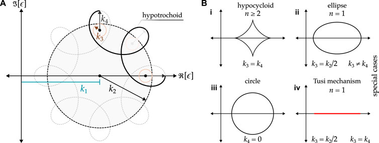
Figure 7
www.frontiersin.org

Figure 7. (A) Complex phase locus of a hypotrochoid shape, shown for n=7, resulting in n+1 internal loops. Its geometrical properties are related to the stiffness parameters in the inverse-designed diatomic lattice (Figure 8). (B) Special cases of the hypotrochoid transforming into simpler geometries, each with their respective parameters.

Under special conditions, a generic hypotrochoid complex phase locus can transform into more simplified geometries (Figure 7B). For instance, it becomes a hypocycloid when k3=k4 and n2 (Figure 7Bi) and an ellipse when n=1, k2=2k3 and k4k3 (Figure 7Bii). In the special case of an ellipse, the minor and major axes are equal to k3k4 and k3+k4, respectively, reinforcing that a zero k4 results in a circle (with a radius of k3) (Figure 7Biii). Additionally, the ellipse collapses to a line when k3=k4, resulting in a looped line, often referred to as the “Tusi mechanism” (Figure 7Biv).

Following Equation 4, a hypotrochoid roulette in the complex plane is defined via the following x and y parametric functions:

x=k1+k2k3cosq+k4cosk2k31q,(20a)
y=k2k3sinqk4sink2k31q.(20b)

As in the case of the epitrochoid, the factor multiplied by the wavenumber in the cosine/sine arguments in Equations 20a, b must be an integer. Therefore, k2/k31=n (or k2=(n+1)k3), which, in combination with Equations 4, and 20a, b yields the following complex phase locus:

ϵ=k1+nk3eiq+k4einq.(21)

After constructing the diatomic lattice corresponding to ϵ in Equation 21, as shown in Figure 8, the following equations of motion for the unit cell are derived:

müj+k1+k2k3+k4ujk1vik2k3vj1k4vj+n=0,(22a)
mv̈j+k1+k2k3+k4vjk1ujk2k3uj+1k4ujn=0,(22b)

Figure 8
www.frontiersin.org

Figure 8. Schematic of a diatomic lattice with coupling beyond next neighbors, resulting in a complex phase locus of hypotrochoid shape.

which, after using k2k3=nk3, simplify to:

müj+k1+nk3+k4ujk1vink3vj1k4vj+n=0,(23a)
mv̈j+k1+nk3+k4vjk1ujnk3uj+1k4ujn=0.(23b)

Topological transitions in lattices featuring hypotrochoid loci are achieved by tuning the stiffness parameters k1, k3, and Equations 23a, 23b k4. As in the case of epitrochoid loci, k1 determines the center position of the complex locus, k2=(n+1)k3 governs the size of the main loop, and k3 and k4 control the size of the internal loops, if present. Mirroring the epitrochoid loci, when the internal loops are significantly smaller than the main loop (i.e., when k4k3), the winding number is either 0 or +1, depending on whether k2k3=nk3 is smaller or greater than k1. As the non-local spring constant k4 increases, the internal loops may begin to wind around the origin in a clockwise direction, and the winding number assumes negative odd or even integers, matching the parity of the integer n. This progression continues until k4nk3, at which point the size of the internal loops approaches that of the main loop. Assuming that k1 remains relatively small, the system reaches its maximum possible winding number, ν=n. A summary of possible winding numbers for hypotrochoid complex loci is provided in Table 3, and examples of winding numbers for various cases of n are detailed in Appendix B.

Table 3
www.frontiersin.org

Table 3. Summary of possible winding numbers for a hypotrochoid complex locus.

Similar to the epitrochoid complex phase loci, the maximum number of Dirac points in the first Brillouin zone is n, matching the difference between the maximum and minimum values of ν.

Using n=5 as an example, we numerically calculate the winding numbers for all combinations of stiffness parameters within the constraint k=k1+nk3+k4. As with the epitrochoid complex phase loci, we identify five distinct winding numbers of ν=0,+1,1,3,and,5, separated by boundaries where the bandgap closes (precisely at |ϵ|=0), as shown in the barycentric triangle in Figure 9. Like the epitrochoid case, when the combination of stiffness parameters relatively small along the transition boundaries between regions of different winding numbers, the bandgap closes, signaling topological transitions. Furthermore, the bandgap reaches its maximum size when k1, nk3 or k4 approaches k (Figure 9). Five representative combinations of stiffness parameters (listed in Table 2) are selected to showcase their corresponding dispersion relations, winding number, and complex phase loci (Figure 10).

Figure 9
www.frontiersin.org

Figure 9. Barycentric triangles, showing the winding numbers (left) and bandgap width (right), for n=5 and swept values k1, k3, and k4, such that k=k1+nk3+k4, for a diatomic lattice with a hypotrochoid complex locus. Five distinct regions are obtained, each of which corresponds to a specific winding number, ν, with boundaries in-between representing the transitional states when the bandgap closes (i.e., when |ϵ|=0). Note that the sole bandgap significantly grows in size when approaching the corners of the Barycentric triangles, when k1k, nk3k, or k4k.
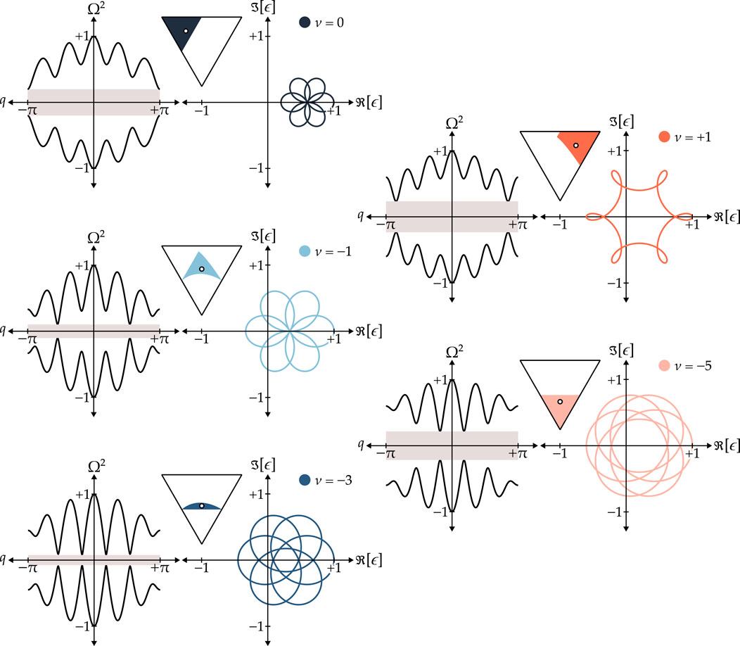
Figure 10
www.frontiersin.org

Figure 10. Dispersion relations and complex phase loci of the five distinct topological states of hypotrochoid diatomic lattices when n=5, obtained by varying stiffness parameters k1, k3, and k4 with the constraint of k=k1+nk3+k4. Choices of k1, k3, and k4 corresponding to each ν are summarized in Table 2. Note that ϵ is normalized with respect to k.

3 Conclusion

Previous studies have demonstrated that topological states in one-dimensional phononic crystals are determined not only by the winding numbers but also by the shapes and trajectories of complex phase loci derived from the off-diagonal elements of the chiral stiffness matrices, which is related to the number of Dirac points in the first Brillouin zone (Rajabpoor Alisepahi et al., 2023). In this study, the characteristics that define the shapes and trajectories of complex phase loci are analyzed. Using these characteristics, we inversely designed intricate networks of diatomic lattices. We focused on three categories of complex phase loci: ellipse, epitrochoid, and hypotrochoid. Our analysis revealed that their shapes and trajectories are influenced by interactions between the diatomic lattice’s degrees of freedom beyond the nearest neighbors. The possible winding numbers emerging in each category of complex phase loci have been studied, and parametric studies are compactly represented via barycentric triangles. The implementation of these complex mechanical networks can be achieved by incorporating non-local interactions as shown by Rajabpoor Alisepahi et al. (2023) and Chen et al. (2021).

The methodologies presented in this study can be extended to higher-dimensional systems by analyzing the characteristics of complex phase surfaces or Berry curvatures. These rigorous tools for designing phononic crystals with desired topological characteristics can enable the rapid and accurate design of phononic and acoustic devices with ideal topological properties, such as one-way wave propagation and multiple localized states. These features will advance the development of mechanical and acoustic technologies, including mechanical computing, noise reduction, and energy harvesting, where topological states offer robust solutions for these applications.

Data availability statement

The original contributions presented in the study are included in the article/supplementary material; further inquiries can be directed to the corresponding authors.

Author contributions

HA: Conceptualization, Data curation, Formal analysis, Investigation, Methodology, Project administration, Resources, Software, Supervision, Validation, Visualization, Writing–original draft, Writing–review and editing. JM: Conceptualization, Data curation, Formal analysis, Investigation, Methodology, Project administration, Resources, Software, Supervision, Validation, Writing–original draft, Writing–review and editing.

Funding

The authors declare that financial support was received for the research, authorship, and/or publication of this article. JM acknowledges the support of the National Aeronautics and Space Administration (NASA Grant 80NSSC23M0071).

Conflict of interest

The authors declare that the research was conducted in the absence of any commercial or financial relationships that could be construed as a potential conflict of interest.

Generative AI statement

The authors declare that no generative AI was used in the creation of this manuscript.

Publisher’s note

All claims expressed in this article are solely those of the authors and do not necessarily represent those of their affiliated organizations, or those of the publisher, the editors and the reviewers. Any product that may be evaluated in this article, or claim that may be made by its manufacturer, is not guaranteed or endorsed by the publisher.

References

Al Ba’ba’a, H., Zhu, X., and Wang, Q. (2021). Enabling novel dispersion and topological characteristics in mechanical lattices via stable negative inertial coupling. Proc. R. Soc. A 477, 20200820. doi:10.1098/rspa.2020.0820

CrossRef Full Text | Google Scholar

Asbóth, J. K., Oroszlány, L., and Pályi, A. (2016). A short course on topological insulators. Lect. notes Phys. 919.

Google Scholar

Bahrami, E., and Bahrami, A. (2024). Three-channel acoustic switch based on topological phononic crystals. Eur. Phys. J. Plus 139, 609. doi:10.1140/epjp/s13360-024-05335-4

CrossRef Full Text | Google Scholar

Cajić, M., Karličić, D., and Adhikari, S. (2024). Inerter-controlled topological interface states in locally resonant lattices with beyond-nearest neighbor coupling. J. Appl. Phys. 135. doi:10.1063/5.0205248

CrossRef Full Text | Google Scholar

Chen, H., Nassar, H., and Huang, G. L. (2018). A study of topological effects in 1D and 2D mechanical lattices. J. Mech. Phys. Solids 117, 22–36. doi:10.1016/j.jmps.2018.04.013

CrossRef Full Text | Google Scholar

Chen, Y., Kadic, M., and Wegener, M. (2021). Roton-like acoustical dispersion relations in 3d metamaterials. Nat. Commun. 12, 3278. doi:10.1038/s41467-021-23574-2

PubMed Abstract | CrossRef Full Text | Google Scholar

Chiu, C.-K., Teo, J. C., Schnyder, A. P., and Ryu, S. (2016). Classification of topological quantum matter with symmetries. Rev. Mod. Phys. 88, 035005. doi:10.1103/revmodphys.88.035005

CrossRef Full Text | Google Scholar

Christiansen, R. E., Wang, F., and Sigmund, O. (2019). Topological insulators by topology optimization. Phys. Rev. Lett. 122, 234502. doi:10.1103/physrevlett.122.234502

PubMed Abstract | CrossRef Full Text | Google Scholar

Dal Poggetto, V., Pal, R., Pugno, N., and Miniaci, M. (2024). Topological bound modes in phononic lattices with nonlocal interactions. Int. J. Mech. Sci. 281, 109503. doi:10.1016/j.ijmecsci.2024.109503

CrossRef Full Text | Google Scholar

Ding, X., Du, Z., Luo, J., Chen, H., Guan, Z., and Guo, X. (2024). Optimal design of fast adiabatic topological pumping in modulated lattices. Appl. Phys. Lett. 124. doi:10.1063/5.0198286

CrossRef Full Text | Google Scholar

Du, Z., Chen, H., and Huang, G. (2020). Optimal quantum valley hall insulators by rationally engineering berry curvature and band structure. J. Mech. Phys. Solids 135, 103784. doi:10.1016/j.jmps.2019.103784

CrossRef Full Text | Google Scholar

Fleury, R., Khanikaev, A. B., and Alu, A. (2016). Floquet topological insulators for sound. Nat. Commun. 7, 11744. doi:10.1038/ncomms11744

PubMed Abstract | CrossRef Full Text | Google Scholar

Grundmann, M. (2020). Topological states due to third-neighbor coupling in diatomic linear elastic chains. Phys. status solidi (b) 257, 2000176. doi:10.1002/pssb.202000176

CrossRef Full Text | Google Scholar

Haldane, F. D. M. (1988). Model for a quantum hall effect without landau levels: condensed-matter realization of the “parity anomaly”. Phys. Rev. Lett. 61, 2015–2018. doi:10.1103/physrevlett.61.2015

PubMed Abstract | CrossRef Full Text | Google Scholar

Hasan, M. Z., and Kane, C. L. (2010). Colloquium: topological insulators. Rev. Mod. Phys. 82, 3045–3067. doi:10.1103/revmodphys.82.3045

CrossRef Full Text | Google Scholar

Jackiw, R., and Rebbi, C. (1976). Solitons with fermion number ½. Phys. Rev. D. 13, 3398–3409. doi:10.1103/physrevd.13.3398

CrossRef Full Text | Google Scholar

Lee, K. H., Al Ba’ba’a, H., Yu, K., Li, K., Zhang, Y., Du, H., et al. (2022). Magnetoactive acoustic topological transistors. Adv. Sci. 9, 2201204. doi:10.1002/advs.202201204

PubMed Abstract | CrossRef Full Text | Google Scholar

Li, S.-F., Lu, J.-Y., Zhou, C.-Y.-Y., Zou, X.-Y., and Cheng, J.-C. (2024). Topological logical elements based on defect-mediated sound-wave manipulation. Phys. Rev. Appl. 22, 034025. doi:10.1103/physrevapplied.22.034025

CrossRef Full Text | Google Scholar

Liu, H., Huang, X., Yan, M., Lu, J., Deng, W., and Liu, Z. (2023). Acoustic topological metamaterials of large winding number. Phys. Rev. Appl. 19, 054028. doi:10.1103/physrevapplied.19.054028

CrossRef Full Text | Google Scholar

Liu, Y., Xu, Y., Zhang, S.-C., and Duan, W. (2017). Model for topological phononics and phonon diode. Phys. Rev. B 96, 064106. doi:10.1103/physrevb.96.064106

CrossRef Full Text | Google Scholar

Ma, J., Sun, K., and Gonella, S. (2019). Valley hall in-plane edge states as building blocks for elastodynamic logic circuits. Phys. Rev. Appl. 12, 044015. doi:10.1103/physrevapplied.12.044015

CrossRef Full Text | Google Scholar

Ma, J., Zhou, D., Sun, K., Mao, X., and Gonella, S. (2018). Edge modes and asymmetric wave transport in topological lattices: experimental characterization at finite frequencies. Phys. Rev. Lett. 121, 094301. doi:10.1103/physrevlett.121.094301

PubMed Abstract | CrossRef Full Text | Google Scholar

Mousavi, S. H., Khanikaev, A. B., and Wang, Z. (2015). Topologically protected elastic waves in phononic metamaterials. Nat. Commun. 6, 8682. doi:10.1038/ncomms9682

PubMed Abstract | CrossRef Full Text | Google Scholar

Nash, L. M., Kleckner, D., Read, A., Vitelli, V., Turner, A. M., and Irvine, W. T. (2015). Topological mechanics of gyroscopic metamaterials. Proc. Natl. Acad. Sci. 112, 14495–14500. doi:10.1073/pnas.1507413112

PubMed Abstract | CrossRef Full Text | Google Scholar

Pal, R. K., Schaeffer, M., and Ruzzene, M. (2016). Helical edge states and topological phase transitions in phononic systems using bi-layered lattices. J. Appl. Phys. 119. doi:10.1063/1.4942357

CrossRef Full Text | Google Scholar

Pal, R. K., Vila, J., Leamy, M., and Ruzzene, M. (2018). Amplitude-dependent topological edge states in nonlinear phononic lattices. Phys. Rev. E 97, 032209. doi:10.1103/PhysRevE.97.032209

PubMed Abstract | CrossRef Full Text | Google Scholar

Pirie, H., Sadhuka, S., Wang, J., Andrei, R., and Hoffman, J. E. (2022). Topological phononic logic. Phys. Rev. Lett. 128, 015501. doi:10.1103/physrevlett.128.015501

PubMed Abstract | CrossRef Full Text | Google Scholar

Politano, A., Viti, L., and Vitiello, M. S. (2017). Optoelectronic devices, plasmonics, and photonics with topological insulators. Apl. Mater. 5. doi:10.1063/1.4977782

CrossRef Full Text | Google Scholar

Qi, X.-L., and Zhang, S.-C. (2011). Topological insulators and superconductors. Rev. Mod. Phys. 83, 1057–1110. doi:10.1103/revmodphys.83.1057

CrossRef Full Text | Google Scholar

Rajabpoor Alisepahi, A., and Ma, J. (2024). In-gap edge and domain-wall states in largely perturbed phononic su–schrieffer–heeger lattices. Crystals 14, 102. doi:10.3390/cryst14010102

CrossRef Full Text | Google Scholar

Rajabpoor Alisepahi, A., Sarkar, S., Sun, K., and Ma, J. (2023). Breakdown of conventional winding number calculation in one-dimensional lattices with interactions beyond nearest neighbors. Commun. Phys. 6, 334. doi:10.1038/s42005-023-01461-0

CrossRef Full Text | Google Scholar

Roman, S., and Sebastian, D. H. (2015). Observation of phononic helical edge states in a mechanical topological insulator. Science 349, 47–50. doi:10.1126/science.aab0239

CrossRef Full Text | Google Scholar

Wang, P., Lu, L., and Bertoldi, K. (2015). Topological phononic crystals with one-way elastic edge waves. Phys. Rev. Lett. 115, 104302. doi:10.1103/PhysRevLett.115.104302

PubMed Abstract | CrossRef Full Text | Google Scholar

Xu, N., Xu, Y., and Zhu, J. (2017). Topological insulators for thermoelectrics. npj Quantum Mater. 2, 51. doi:10.1038/s41535-017-0054-3

CrossRef Full Text | Google Scholar

Zhou, D., Ma, J., Sun, K., Gonella, S., and Mao, X. (2020). Switchable phonon diodes using nonlinear topological maxwell lattices. Phys. Rev. B 101, 104106. doi:10.1103/physrevb.101.104106

CrossRef Full Text | Google Scholar

Appendix A: Mathematical model of typical diatomic lattices

Consider the jth unit cell of the diatomic lattice shown in Figure 1A, which is comprised of identical masses m and alternating springs k1 and k2. The unit cell has two degrees of freedom, denoted uj and vj, with the following equations of motion:

müj+k1+k2ujk1vjk2vj1=0,(A.1a)
mv̈j+k1+k2vjk1ujk2uj+1=0.(A.1b)

Next, we define the degrees of freedom vector uj(t)=ujvjT and the Bloch-wave solution:

ujt=ũqeijqaωt,(A.2)

where ũj(q)=ũjṽjT is the complex amplitude vector, a is the lattice constant (assumed to be one throughout this work), i=1 is the imaginary unit, q is the wavenumber, ω is the frequency, and t is time. By plugging in Equation A.2 into Equation A.1, the equations of motion can be cast into an eigenvalue problem:

Kqũq=mω2ũq,(A.3)

where K(q) is the stiffness matrix and is given by:

Kq=kϵϵk.(A.4)

The constant diagonal elements of K(q) are k=k1+k2, and the superscript denotes the complex conjugate of the off-diagonal component ϵ (i.e., the complex phase locus). The dispersion relation can be derived by finding the eigenvalues of Equation A.3 as:

ω=1mk±|ϵ|.(A.5)

Interestingly, shifting the eigenvalues of matrix K(q) by k (equivalently shifting ω2 by k/m) does not influence the topological properties of the diatomic lattice, given the constant diagonal elements of the matrix. As such, we shall focus on the topological properties of the chiral matrix:

Cq=Kqkσ0=0ϵϵ0,(A.6)

resulting in the following eigenvalue problem:

Cqũq=mλũq,(A.7)

where λ=ω2k/m is the shifted eigenvalue and σ0 represents the zeroth Pauli matrix (equal to an identity matrix of size 2×2).

Appendix B: Numerical simulations for winding numbers

For various values of n, the possible winding numbers for both epitrochoid and hypotrochoid complex phase loci are numerically generated under the constraint k=k1+nk3+k4. A summary of these winding numbers is provided in Table A1.

TABLE A1
www.frontiersin.org

TABLE A1. Examples of the winding numbers generated for the epitrochoid and hypotrochoid complex phase loci with various n values.

Keywords: diatomic lattice, winding number, dispersion analysis, complex phase, inverse design, epitrochoid, hypotrochoid, ellipse

Citation: Al Ba’ba’a HB and Ma JA (2025) Inverse design of topological diatomic lattices based on complex phase locus. Front. Acoust. 3:1529474. doi: 10.3389/facou.2025.1529474

Received: 17 November 2024; Accepted: 18 February 2025;
Published: 02 April 2025.

Edited by:

Raj Kumar Pal, Kansas State University, United States

Reviewed by:

Georgios Theocharis, UMR6613 Laboratoire d’Acoustique de l’Universite du Maine (LAUM), France
Murat Kaynak, Harvard Medical School, United States
Patrick Andrew Dorin, University of Michigan, United States
Zongliang Du, Dalian University of Technology, China

Copyright © 2025 Al Ba’ba’a and Ma. This is an open-access article distributed under the terms of the Creative Commons Attribution License (CC BY). The use, distribution or reproduction in other forums is permitted, provided the original author(s) and the copyright owner(s) are credited and that the original publication in this journal is cited, in accordance with accepted academic practice. No use, distribution or reproduction is permitted which does not comply with these terms.

*Correspondence: Hasan B. Al Ba’ba’a, YWxiYWJhYWhAdW5pb24uZWR1; Jihong A. Ma, amlob25nLk1hQHV2bS5lZHU=

These authors have contributed equally to this work

Disclaimer: All claims expressed in this article are solely those of the authors and do not necessarily represent those of their affiliated organizations, or those of the publisher, the editors and the reviewers. Any product that may be evaluated in this article or claim that may be made by its manufacturer is not guaranteed or endorsed by the publisher.

Research integrity at Frontiers

Man ultramarathon runner in the mountains he trains at sunset

95% of researchers rate our articles as excellent or good

Learn more about the work of our research integrity team to safeguard the quality of each article we publish.


Find out more