- 1Key Laboratory of Conveyance and Equipment, Ministry of Education, East China Jiaotong University, Nanchang, China
- 2School of Basic Science, East China Jiaotong University, Nanchang, China
Introduction: Planetary-face gears combine the advantages of both planetary and face gears, offering potential value for wind power applications. During the gear meshing process, a large amount of heat is generated, and tooth wear also occurs, which affects transmission performance.
Methods: Analyzing multiple factors such as lubrication performance and thermal effects of meshing pairs plays a crucial role in improving the overall lifespan of transmission systems. This study developed a nonlinear dynamic model of a wind power planetary-face gear system, considering factors like random wind load, tooth surface friction, temperature rise, tooth side clearance, and elastic lubrication. Nonlinear methods such as bifurcation diagram, maximum Lyapunov exponent diagram, and time-frequency diagram were used to analyze the effects of wind turbine radius, average wind load, temperature rise, and lubricant viscosity on the dynamic response of the gear transmission system under random wind loads.
Results: The results show that selecting an appropriate wind turbine radius for different wind loads is essential to enhance system stability. Higher lubricant viscosity can suppress chaotic phenomena in gear systems. For a well lubricated gear system, tooth surface temperature rise is a key factor affecting the dynamic characteristics of the system.
Discussion: This article aims to provide valuable insights into improving the operational stability of the wind turbine planetary gear system.
1 Introduction
As the worldwide demand for energy steadily rises alongside heightened environmental consciousness, the significance of harnessing clean and renewable energy sources has grown significantly more paramount. Wind energy, being a boundless green energy source, has garnered substantial attention and developed rapidly in recent years. The wind turbine gear transmission system, an essential component of wind turbines, is designed to transmit torque and adjust speed. Most current wind power gear transmission systems consist of a first-stage planetary gear and a first-stage cylindrical gear, featuring a single input from the wind turbine and a single output to the generator. This article proposes a single input dual output transmission structure using planetary gears and face gears. This configuration links multiple generators, allowing them to produce electricity simultaneously and thereby improving wind energy utilization efficiency. Planetary gears provide advantages like a compact design, efficient transmission, smooth performance, and robust shock resistance. Face gears possess the benefits of high load-bearing capacity and minimal vibration noise. The dynamic properties of gear transmission systems can influence the stability and reliability of gear mechanisms. Hence, investigating the nonlinear dynamic characteristics of planetary-face gear systems in wind turbines is valuable.
Many researchers have delved into the dynamic characteristics of gears. Kahraman [1–3] developed models for single-degree-of-freedom gear transmission systems and three-degree-of-freedom gear-bearing systems. They explored the impact of time-varying mesh stiffness and bearing clearance on the vibration characteristics of gear transmission systems; A dynamic model of gear transmission system translation torsion was established by Xiang [4, 5], bifurcation diagrams and maximum Lyapunov exponent diagrams were simulated to investigate how changes in excitation frequency and support stiffness affect the vibration response of gear transmission systems; Li et al. [6] studied the effects of excitation frequency and meshing damping ratio on the bifurcation and chaos characteristics of two-stage planetary gear transmission systems; Mo [7] et al. constructed a nonlinear dynamic model for a herringbone gear transmission system. They investigated how torque, mesh stiffness, and mesh damping affect the nonlinear dynamic characteristics of gears. Their findings suggested that increasing mesh damping and mesh stiffness tends to enhance the stability of the gear system; Hou [8] et al. devised a nonlinear model for the GTF planetary gear rotor system. They examined the vibration response between the gear and rotor to explore the model’s nonlinear behavior. Their findings suggested that increasing damping could potentially cause the system to enter a chaotic state; Many studies in the literature have investigated the effects of meshing stiffness, tooth surface friction, and tooth side clearance. They have developed nonlinear dynamic models for fixed-axis spur planetary gear rotor bearing systems used in gearbox transmissions for turbofan engines [9–11]; Most of the above studies use system bifurcations and chaos to analyze it, and bifurcations and chaos are also widely used in other fields. Min [12] et al. conducted the first study on coexistence phenomena in power systems with different fourth-order time delays. They analyzed the characteristics of time-delay systems using bifurcation diagrams, phase diagrams, etc., under the conditions of mechanical power, generator damping factor, exciter gain, and time delay variations; The dynamic behavior of Shinriki circuit modified with hybrid diodes was studied, and multiple coexisting oscillations and anti-monotonic evolution were discovered by changing circuit parameters. The bifurcation tree and orbital stability of coexisting periodic oscillations were analyzed in depth using semi analytical methods, and the correctness of the analysis was verified through FPGA. This study contributes to the improvement of nonlinear circuits [13]; Liu [14] et al. analyzed the lateral and torsional response characteristics of the gear transmission system by varying the gear speed, backlash, and eccentricity values; Chen [15] et al. developed a multi-degree-of-freedom nonlinear dynamic model for a gear transmission system. The model considered tooth side clearance, friction, and time-varying meshing stiffness; A dynamic model of helicopter face gear planetary gear torsional translation vibration was established by Mo [16] et al, taking into account time-varying mesh stiffness, backlash, gear eccentricity error, and friction. The primary resonance characteristics of the system were analyzed, yet this structure has not been applied in the field of wind power, and the coupled effects of multiple factors were not taken into account.
Furthermore, numerous scholars have investigated the temperature increase caused by gear friction and formulated dynamic models that incorporate nonlinear factors like thermal deformation of the gears [17–20]; Li [21] et al. studied the temperature distribution in involute gears and determined the amount of thermal deformation and changes in tooth side clearance resulting from thermal effects; Gears generate friction during the meshing process, and it is generally assumed that time-varying meshing stiffness and sliding friction result in a uniform distribution of load between the teeth of the gears [22–24]; Kolivand [25] et al. discovered that the rotation of gears alters the thickness of the lubricating oil film, leading to changes in the friction force on the tooth surfaces; Wang [26] et al. developed an electromechanical planetary gear system and analyzed the impact of tooth surface temperature rise on the nonlinear dynamics of the system. They considered factors such as time-varying mesh stiffness, mesh damping, tooth side clearance, and motor speed in their analysis; Tooth friction is increasingly being incorporated into gear models. He [27] et al. established a gear transmission system and extensively considered sliding friction and time-varying stiffness, taking into account gear tooth modification conditions. They conducted detailed research on the impact of friction on the forces along the vertical meshing line direction. All the analyses discussed above were conducted using theoretical gear models and did not explicitly specify practical applications.
The wind turbine gearbox is a critical component of wind turbines, and numerous scholars have conducted extensive research on its various aspects; Zhao [28] et al. studied how dynamic characteristics of wind turbine gear transmission systems are influenced by factors like time-varying mesh stiffness and transmission errors; Chen [29] et al. analyzed how wind speed and tooth side clearance affect the vibration characteristics of wind turbine gear transmission systems under varying environmental wind speeds; In addition, Qin [30] et al. developed a dynamic model of wind power gear transmission systems and analyzed their dynamic characteristics under sinusoidal wind speeds; Zhu [31] et al. developed a dynamic model for a multi-stage gear transmission system in wind turbine gearboxes. They integrated time-varying meshing stiffness, tooth side clearance, and errors, and analyzed its dynamic characteristics; Liu [32] et al. analyzed a model of high-speed gear transmission systems for wind turbines. They investigated the effects of time-varying wind loads, electromagnetic torque disturbances, eccentricity, backlash, and friction on the dynamic response of these systems under random conditions. The aforementioned research analyzed the effects of factors like wind speed variations on the dynamic characteristics of wind power gear transmission systems. However, it did not comprehensively address the influences of lubrication, tooth surface friction, and temperature on the nonlinear dynamics of gear transmission systems. Overall, current research primarily concentrates on single-stage gear meshing pairs with multi-factor coupling and planetary gear systems with limited factor coupling. There remains a relative scarcity of research on the nonlinear dynamics of composite gear transmission systems under the collective influence of multiple factors, particularly in the context of wind power planetary-face gear transmission systems as discussed in this article.
This article integrates the impact of temperature on lubricating oil viscosity and tooth side clearance, along with the effect of lubrication on tooth surface friction. A nonlinear dynamic model of a wind power planetary-face gear system is developed, considering factors such as random wind speed, tooth surface friction, elastic lubrication, temperature, time-varying meshing stiffness, transmission error, meshing damping, and tooth side clearance. Under random wind loads, the dynamic response of gear transmission systems was analyzed using nonlinear methods such as time history plots, 3D phases diagrams, time-frequency plots, phase trajectory plots, FFT spectrograms, Poincaré cross-sections, bifurcation plots, and maximum Lyapunov exponent plots. Factors including wind turbine radius, average wind speed, temperature rise, and lubricant viscosity were considered. This analysis provides theoretical guidance for the structural design of wind power gear transmission systems and the selection of optimal operating conditions.
2 Wind speed model
2.1 Basic wind
Fundamental winds are variations in the average wind speed in a wind field that persist throughout the operation of a wind turbine and significantly affect the transmission of rated power to the system. Simulation of the base wind model does not require consideration of the actual distribution of wind speeds. Typically, the fundamental wind speed is considered to be the average wind speed acting on the wind turbine and can be defined as a specific constant value as shown in Equation 1:
2.2 Random wind
Random wind refers to the fluctuations in wind speed, denoted by the random wind speed
In the formula:
The input and output torque of the wind turbine gear transmission system can be determined using aerodynamic principles and the Bates formula [32] as shown in Equations 4, 5:
In the formula:
3 Dynamic model of wind power planetary-face gear transmission system
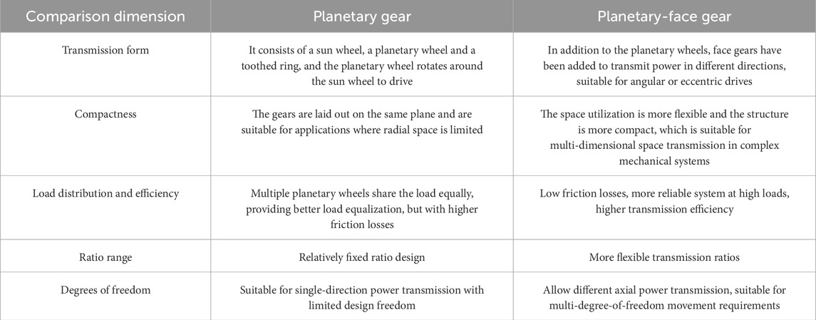
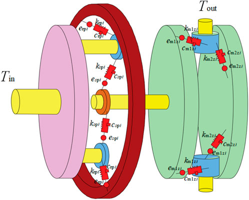
Wind turbine gearing systems typically use planetary gears or a combination of planetary gears and cylindrical spur gears, featuring a two-stage speed increase. The wind power gearbox system described in this article utilizes planetary gears in the first stage and face gear transmission in the second stage. This structure utilizes the benefits of planetary and face gears to achieve secondary speed enhancement. The advantages of the planetary gear-face gear system over the planetary gear system are shown in Table 1.
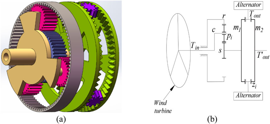
Figure 1A illustrates a simplified three-dimensional schematic of a planetary-face gearing system, while Figure 1B shows a transmission sketch of the system. The wind turbine is connected to the planetary carrier
3.1 Tooth side clearance under temperature influence
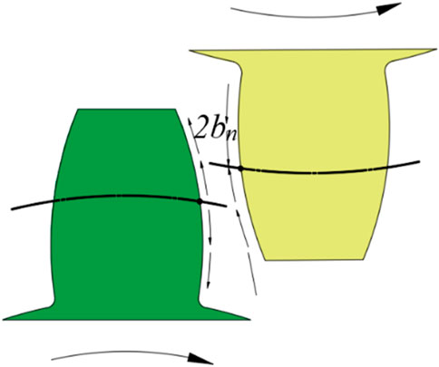
Tooth side clearance in gear manufacturing and assembly causes the meshing trajectory to change during operation. Repeated load effects impact meshing accuracy and gear lifespan. Thus, tooth side clearance is crucial in analyzing the nonlinear dynamic characteristics of gears.
Assuming that the expression for the relative displacement of gears along the meshing line is as shown in Equation 6:
In the formula:
During gear operation, factors like tooth friction can lead to power loss within the gear system. In a stable working state, well-lubricated gears can assume a uniform temperature field.
In the formula:
In the formula: thermal expansion coefficients of the two gears are designated as
In summary, the change in clearance caused by temperature in gears is
3.2 Lubricating oil viscosity under temperature influence
In the absence of lubricating oil during gear operation, teeth come in direct contact, leading to heightened friction and wear. Introducing lubricating oil creates a film between contact surfaces, preventing direct gear contact and significantly reducing wear. Temperature fluctuations affect the lubrication efficacy of oil by changing its viscosity, a key parameter of oil performance. According to Sutherland equation, the expression between lubricant viscosity and temperature change can be derived [35] shown in Equation 16:
In the formula:
3.3 Lubricating friction arm and friction torque
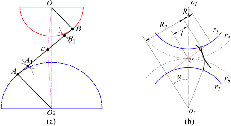
A simplified diagram in Figure 3A illustrates the engagement between two gears. Point
The sliding speed of meshing point
Among them,
Utilizing the comprehensive Equations 18, 19, the sliding velocity at the meshing point
The friction force arm can be written as shown in Equation 21:
The frictional force and torque experienced by the two gears can be calculated as follows, taking into account the relevant factors and Equations 22, 23:
In the formula:
The friction coefficient on gear surfaces varies during meshing due to the presence of lubricating oil. Figure 3B depicts the instantaneous curvature radius of a pair of meshing gears. Consequently, the friction coefficient of the tooth surface can be determined based on this geometric characteristic and the properties of the lubricating oil present during the meshing process [36]; as shown in Equation 25:
Among them:
In the formula:
3.4 Time-varying mesh stiffness and mesh damping
During meshing, gears can be simplified as a cantilever beam consisting of a combination of trapezoidal and rectangular shapes. Thus, when shifting the meshing point from the gear crest to its root, the meshing stiffness undergoes periodic variations:
In the formula:
In the formula:
In the formula:

Figure 4. Gear pair mesh stiffness curve (A)sun Gear planetary Gear mesh pair (B)sun Gear inner ring Gear mesh pair (C)spur Gear face Gear mesh pair.
The meshing damping of gear pairs can be obtained through empirical formulas as shown in Equation 30:
In the formula: Respectively,
The Reynolds equation can be expressed as:
Solve Equation 32 to derive the expression Equation 33 for the oil film damping force:
In the formula:
3.5 Meshing error
The representation of meshing error can be achieved through the utilization of Fourier series as shown in Equation 34:
In the formula:
In the formula:
3.6 Dynamic equations
Create a simplified pure torsional model for a wind power planetary-face gear system utilizing the lumped mass approach, depicted in Figure 5, with the following assumptions: All gears are installed as standard; Assuming rigid body behavior for all gears, the interacting pair is modeled as a spring-damping system for simplicity; The friction and lubrication properties are considered uniform across all system components; Lateral vibration displacement of gears is disregarded in the model; Without considering the stiffness of the shaft, the sun gear
The degrees of freedom of the planetary-facing gear system were first determined, and for the system studied in this paper, only the torsional direction displacement was investigated. Each gear assembly is reduced to a centralized mass point with the mass distribution concentrated by the center of mass. For the rotational degrees of freedom, the gears are considered as equivalent rotational inertia in order to simplify to a mass-spring-damping system with single or multiple degrees of freedom, and secondly, each gear meshing pair is considered as a spring and damping unit. The springs represent the effect of the gears on the meshing stiffness, while the damping represents the energy dissipation characteristics of the system, and finally the dynamical equations are developed according to Newton’s second method. In this paper, only the torsional degrees of freedom are considered. The elastic deformation of each gear along the meshing line direction is:
Establish system dynamics equations using the Newton Euler method:
In the formula:
In order to facilitate numerical solutions and improve the stability of the calculation process, it is necessary to dimensionless the dynamic equations. Define dimensionless time as
4 Nonlinear dynamic analysis of the system
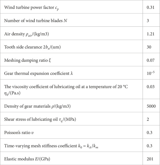
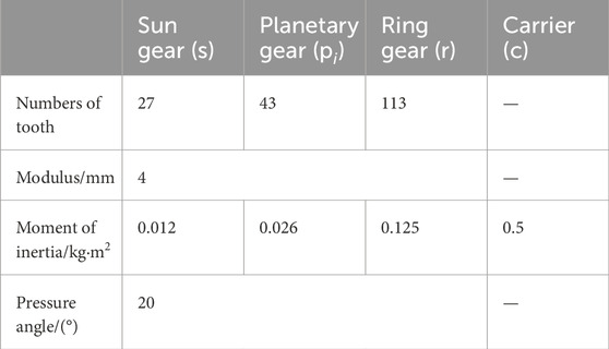
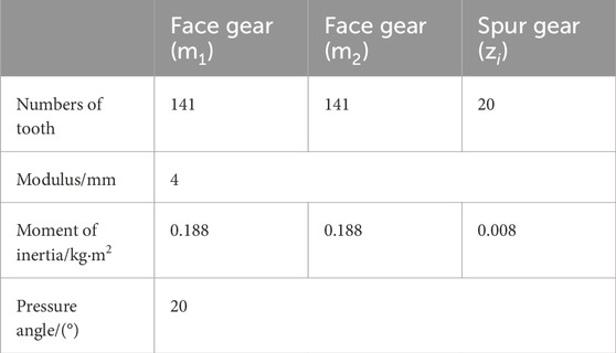
This article employs the Runge Kutta method to solve the system’s vibration equation. Various analytical tools, including global bifurcation diagrams, time history diagram, maximum Lyapunov exponent plots, phase trajectory diagram, FFT spectrum diagram, Poincaré section diagram, 3D phase diagram and time–frequency diagram, are utilized to investigate the bifurcation and chaotic characteristics under varying system parameters. The fundamental gear parameters are detailed in Tables 2–4, [37, 38].
4.1 The influence of average wind speed and wind turbine radius on the nonlinear characteristics of the system
Wind speed directly affects the performance of the entire power generation system during wind turbine operation. Establishing a random wind speed model is essential for simulating the nonlinear dynamic response of wind speed in the gear transmission system of the turbine. Figure 6 illustrates the dynamic simulation of random wind speed under average wind speeds of 5 m/s, 10 m/s, and 15 m/s.

Figure 6. Random wind speed curves under different average wind speeds. (A)
In the random wind speed model, higher average wind speeds cause greater fluctuations and amplitudes in the wind speed curve. Using aerodynamic principles, the input torque curve of the wind turbine gear system can be modeled and simulated, as shown in Figure 7. To maintain the randomness of gear system excitation from the wind turbine input, the torque data from the first 10 seconds is used as the system’s input excitation. As average windspeed increases, the torque input from the wind turbine system also rises. Torque variations and torque wave momentum impact the gear system’s dynamic characteristics. Thus, analyzing the impact of average wind speed on the nonlinear dynamic characteristics of wind power gears is highly significant.

Figure 7. Input torque curves under different average wind speeds. (A)
Analyzing the nonlinear dynamic characteristics of the system involves setting the system temperature rise to 60°C, with a time-varying mesh stiffness coefficient of 0.3, mesh damping ratio of 0.07, mesh error amplitude of 0.35, initial tooth side clearance of 30 microns, dimensionless excitation frequency of 1 [39]. The analysis spans average wind speeds from 0 m/s to 20 m/s.
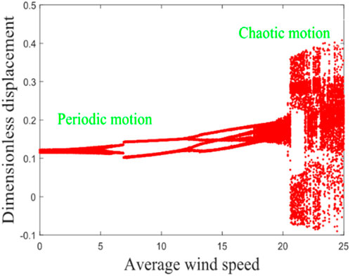
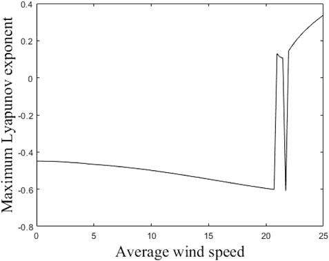
Figure 8 shows the bifurcation of the gear system as the mean wind speed varies. The bifurcation diagram shows a clear bifurcation in the range of mean wind speed from 0 m/s to 17.5 m/s. Figure 9 shows the maximum Lyapunov exponent of the system as a function of the mean wind speed. In the above wind speed range, the maximum Lyapunov exponent stays below 0, indicating the presence of periodic motion in the system. When the mean wind speed is between 0 m/s and 5 m/s, the system shows a single-period motion. When the mean wind speed is between 5 m/s and 12 m/s, the system is in double periodic motion. Between 12 m/s and 17.5 m/s, the system is in a four-cycle state. When the mean wind speed increases between 17.5 m/s and 25 m/s, the bifurcation diagram does not show any obvious bifurcation and the maximum Lyapunov exponent of the system is constant greater than 0, which suggests that there is unstable chaotic motion in this range.
To further verify the global bifurcation diagram of the gear system with varying average wind speed, we analyzed phase trajectory diagrams, time-domain plots, Poincaré cross-sections, FFT spectrum diagrams 3D phase diagram and time–frequency diagram of the gear system at average wind speeds of 2 m/s, 10 m/s, 15 m/s, and 23 m/s.
Figure 10 depicts the time-domain plot, phase trajectory, FFT spectrum, and Poincaré cross-section of the system at an average wind speed of 2 m/s. The time domain plot exhibits clear periodicity, while the phase trajectory forms a closed curve encircling a circle. A peak is evident in the FFT spectrum, and a discrete point appears in the Poincaré cross-section, indicating that the gear system is in a single-cycle motion state at this time; The illustration in Figure 11 presents various diagrams including the time domain, phase trajectory, FFT spectrum, and Poincaré cross-section, all depicting the system’s behavior at an average wind velocity of 10 m/s. The time-domain graph displays a curve featuring two distinct periods, paralleled by the phase trajectory with two enclosed loops. The FFT spectrum exhibits two peaks, and the Poincaré cross-section identifies two separate points, suggesting the gear system has transitioned into a two-cycle motion state at present; Figure 12 shows the time domain diagram, phase trajectory diagram, FFT spectrum diagram, and Poincaré cross-section diagram of the system at an average wind speed of 15 m/s, indicating that the gear system has entered a four period motion state at this time; At an average wind speed of 23 m/s, the gear system demonstrates an unstable chaotic motion. Figure 13 illustrates the system’s time-domain, phase trajectory, FFT spectrum, and Poincaré cross-section at this velocity. Figures 14, 15 present time-frequency and 3D phase diagrams, respectively, showcasing the system’s behavior across varying wind speeds. It is evident that with rising wind speeds, the system progressively shifts from stability to instability.
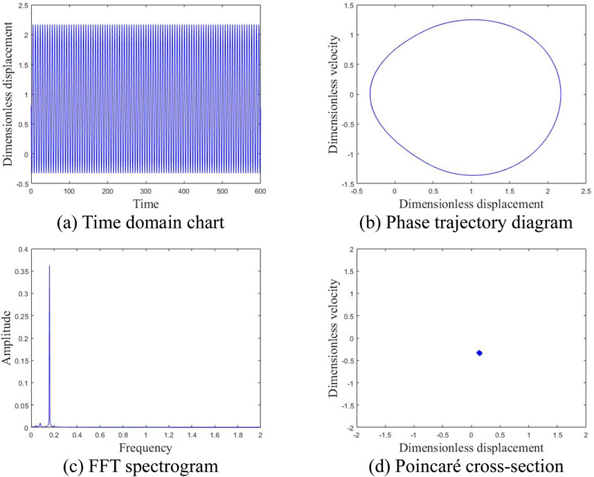
Figure 10. Motion state of the system at an average wind speed of 2 m/s. (A) Time domain chart. (B) Phase trajectory diagram. (C) FFT spectrogram. (D) Poincaré cross-section.
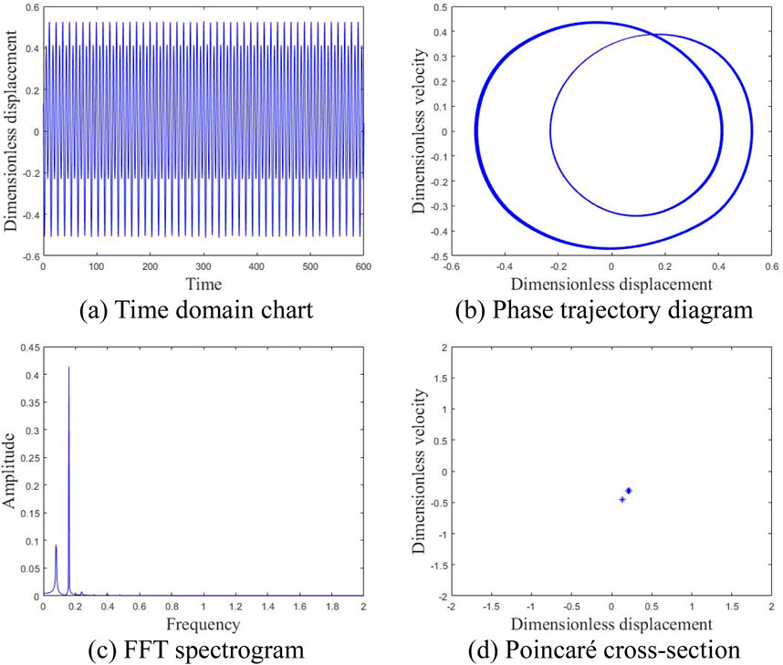
Figure 11. Motion state of the system at an average wind speed of 10 m/s. (A) Time domain chart. (B) Phase trajectory diagram. (C) FFT spectrogram. (D) Poincaré cross-section.
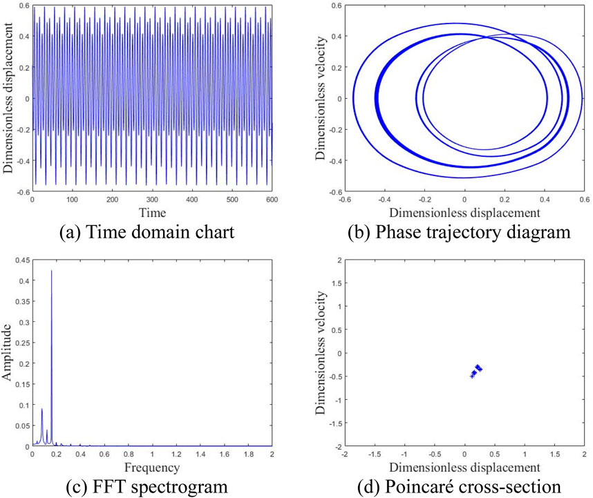
Figure 12. Motion state of the system at an average wind speed of 15 m/s. (A) Time domain chart. (B) Phase trajectory diagram. (C) FFT spectrogram. (D) Poincaré cross-section.
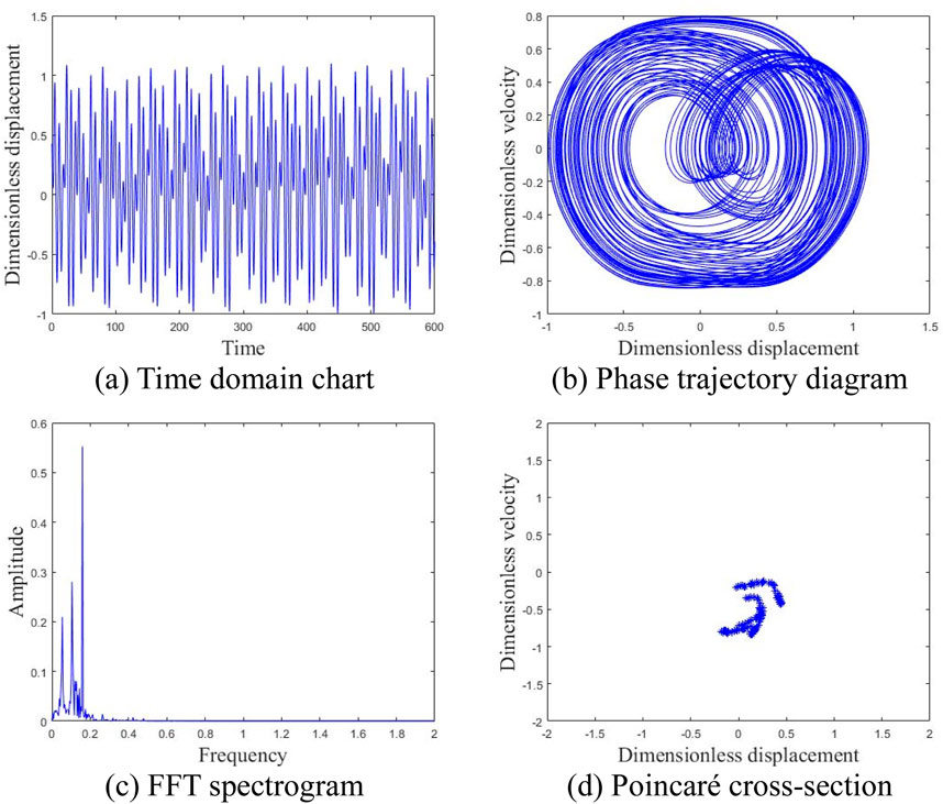
Figure 13. Motion state of the system at an average wind speed of 23 m/s. (A) Time domain chart. (B) Phase trajectory diagram. (C) FFT spectrogram. (D) Poincaré cross-section.

Figure 14. Time frequency plot with increasing average wind speed. (A) Random wind speed of 2 m/s. (B) Random wind speed of 15 m/s. (C) Random wind speed of 23 m/s.

Figure 15. Phase diagram with increasing average wind speed. (A) Random wind speed of 2 m/s. (B) Random wind speed of 15 m/s. (C) Random wind speed of 23 m/s.
The study reveals that the average wind speed significantly influences system characteristics. As it rises, the system transitions from periodic to chaotic motion, consequently, this wind power gear system is optimally suited for regions with an annual average wind speed below 17.5 m/s.
Variations in the radius of the wind turbine for a constant mean wind speed can change the aerodynamic performance and thus affect the input torque of the geared system. Therefore, wind turbine dimensions are valuable variables for exploring the nonlinear dynamics of the gear system. A time-varying meshing stiffness factor of 0.3, a damping ratio of 0.07, a meshing error magnitude of 0.35, an initial tooth side clearance of 30 μm, a dimensionless excitation frequency of 1, and an operating environment with an average wind speed of 10 m/s are set for a system temperature rise of 60°C. The nonlinear dynamic behavior of the system is analyzed for a range of wind turbine radii from 0 m to 30 m. The system is then subjected to a time-varying meshing stiffness coefficient of 0.3.
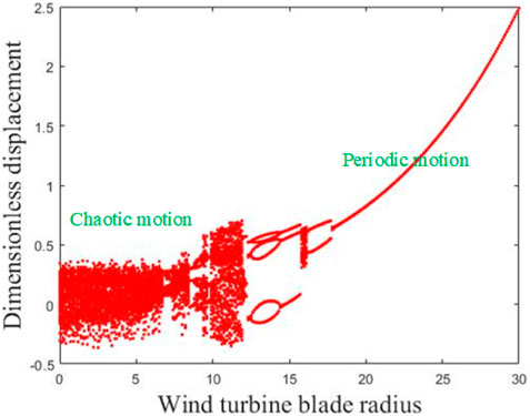
Figure 16 depicts the global bifurcation diagram of the gear system with the variation of wind turbine radius. Within the range of 0–12 m, there is a noticeable chaotic phenomenon in the graph. Figure 17 shows the maximum Lyapunov exponent as a function of radius; The index is always greater than 0 within the range of 0–12 m. When the radius is 14–16 m, the bifurcation diagram shows a three-period motion, and the maximum Lyapunov exponent is also negative. At a distance of 16–17.5 m, the bifurcation diagram shows a two-period motion with a constant negative exponent. Finally, stable single period motion occurs at 17.5–30 m, with a maximum negative Lyapunov exponent.
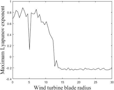
Figure 17. Maximum Lyapunov exponent diagram of the system with the variation of wind turbine radius.
To validate the global bifurcation diagram of the gear system across varying wind turbine radii, phase trajectory, time domain, Poincaré section, FFT spectrum diagrams, 3D phase diagram and time–frequency diagram were analyzed specifically for radii of 5 m, 13 m, 15 m, 17 m, and 23 m.
Supplementary Figure S1 shows the time-domain, phase trajectory, FFT spectrum, and Poincare section of a 5 m wind turbine radius, indicating chaotic motion. Supplementary Figure S2 shows that when the radius of the wind turbine is 13 m, the system is in a six-cycle motion state. As the radius increases, Supplementary Figure S3 shows that the wind turbine system is in a three-cycle motion state at a radius of 15 m, Supplementary Figure S4 depicts the transition of the system to a two-cycle motion state at a radius of 17 m, and Supplementary Figure S5 depicts a stable single cycle motion at a radius of 23 m. Supplementary Figures S6, S7 show the time-frequency and 3D phase diagrams at different radii, respectively. It can be seen that increasing the radius of the wind turbine will cause the gear system to stabilize at a constant wind speed.
The findings indicate that the wind turbine radius significantly influences system behavior. As the radius increases, the system transitions from chaotic motion to periodic states (six-period, three-period, two-period, and single-period). The global bifurcation diagram illustrates increasing system stability with greater turbine radius. Systems with radius less than 12 m exhibit chaotic behavior, increasing gear collision severity and accelerating wear. Optimal operating speeds should be chosen to avoid prolonged exposure to chaotic conditions, recommending a wind turbine radius exceeding 12 m for system stability.
Supplementary Figure S8 shows the relationship between the maximum Lyapunov exponent of the gear system and the radius and average wind speed of the wind turbine. In the case of a small radius of a wind turbine, regardless of changes in wind speed, the gear system will maintain a chaotic state, indicating that the radius of the wind turbine is the main factor affecting system chaos in the same working environment. When the radius of the wind turbine is large and the wind speed is low, the gear system tends to stabilize.
4.2 The influence of temperature rise and lubricating oil viscosity on the nonlinear characteristics of the system
Due to the complex operating conditions of most wind power gear systems, factors such as sunlight exposure and power loss during high-speed operation can lead to increased gear surface temperatures. Additionally, environmental temperatures vary across different regions, necessitating an analysis of temperature rise effects on the system. The gear system parameters include a time-varying meshing stiffness coefficient of 0.3, meshing damping ratio of 0.07, meshing error amplitude of 0.35, initial tooth side clearance of 30 microns, dimensionless excitation frequency of 1. The average wind speed in the region is set to 10 m/s.
Supplementary Figure S9 shows the bifurcation diagram of the gear system with temperature rise. Supplementary Figure S10 shows the maximum Lyapunov exponent of the corresponding gear system. From 0°C to 55°C, the bifurcation diagram indicates that the gear system is in unstable chaotic motion, and the maximum Lyapunov exponent is always positive. When the temperature rise range is from 55°C to 61°C, the bifurcation diagram indicates that the gear system is in double periodic motion, and the Lyapunov exponent remains negative. The temperature rise range is from 61°C to 100°C, and the bifurcation diagram indicates that the gear system is in single cycle motion. At this stage, the maximum Lyapunov exponent remains negative.
In order to accurately illustrate the motion characteristics, the phase trajectory diagram, time-domain diagram, Poincare section diagram, FFT spectrum diagram, 3D phase diagram, and time-frequency diagram of the gear system were analyzed at temperatures of 30°C, 59°C, and 90°C.
Supplementary Figure S11 displays the system’s time-domain, phase trajectory, FFT spectrum, and Poincaré cross-section diagrams with a 30°C rise in gear temperature, indicating unstable chaotic motion. Supplementary Figure S12 illustrates these diagrams with a 59°C temperature rise, showing the system in a two-cycle motion state. Supplementary Figure S13 depicts these diagrams with a 90°C temperature rise, indicating the system is in single-cycle motion. Supplementary Figure S14 shows the time-frequency diagram of the system at different temperature rises, indicating that as the system temperature increases, it transitions from chaotic motion to single period stable motion. Supplementary Figure S15 shows the 3D phase diagram of the system at different temperature rises, which can further illustrate its dynamic behavior.
The results indicate that as the temperature of the gear system increases, it transitions from chaotic motion to periodic motion, experiencing chaotic, bi periodic, and single periodic states. When the temperature rises to 55°C, the system is in a long-term chaotic state, and gear collisions increase.
Wind power gear system in the process of operation, usually add lubricant, lubricant will be added to form an oil film on the gear surface, which can not only avoid direct contact with the gear, but also reduce the friction of the gear surface in the process of work, slowing down the wear of the tooth surface. The lubrication performance of the lubricant is mainly reflected in the lubricant viscosity, so the effect of lubricant viscosity on the nonlinear dynamic characteristics of the gear system can be analyzed. The time-varying meshing stiffness coefficient of the gear system is set to be 0.3, the meshing damping ratio to be 0.07, the magnitude of the meshing error to be 0.35, the initial tooth flank clearance to be 30 μm, the dimensionless excitation frequency to be 1, the temperature rise of the gears to be 60°C, and the average wind speed of the wind machine’s working area to be set to be 10 m/s.
Supplementary Figure S16 displays the global bifurcation diagram of the gear system as the viscosity of the lubricating oil varies from 0.01 Pa·s to 0.1 Pa·s. Supplementary Figure S17 shows the maximum Lyapunov exponent of the gear system with changing viscosity of the lubricating oil. For viscosity values between 0.01 Pa·s and 0.016 Pa·s, the bifurcation diagram indicates the gear system is in unstable chaotic motion, with a consistently positive maximum Lyapunov exponent. As viscosity increases to between 0.016 Pa·s and 0.022 Pa·s, the system exhibits two-period motion, with a negative maximum Lyapunov exponent. When viscosity ranges from 0.022 Pa·s to 0.1 Pa·s, the system shows single-cycle motion, maintaining a negative maximum Lyapunov exponent throughout this range.
To accurately determine the motion characteristics, the gear system’s phase trajectory diagram, time domain chart, Poincaré section diagram, FFT spectrum diagram, 3D phase diagram and time–frequency diagram was analyzed at lubricating oil viscosities of 0.01 Pa·s, 0.02 Pa·s, and 0.05 Pa·s.
Supplementary Figure S18 depicts the time-domain diagram, phase trajectory, FFT spectrum, and Poincaré cross-section of a gear system lubricated with oil viscosity of 0.01 Pa·s, showing the system in an unstable chaotic motion state. Supplementary Figure S19 illustrates the time-domain diagram, phase trajectory diagram, FFT spectrum diagram, and Poincaré cross-section diagram of the system at 0.02 Pa·s viscosity, indicating the system has entered a two-cycle motion state. Supplementary Figure S20 shows the time-domain diagram, phase trajectory diagram, FFT spectrum diagram, and Poincaré cross-section diagram of the system at 0.05 Pa·s viscosity, where the system has entered a single-cycle motion state. Supplementary Figure S21 shows the time-frequency diagram of the system. It can be seen that as the viscosity of the lubricating oil increases, the system gradually becomes a single cycle motion and tends to stabilize. Under chaotic motion, the time-frequency diagram is a discrete spectrum with a certain width. Supplementary Figure S22 shows a three-dimensional phase diagram of the system when the viscosity of the lubricating oil changes. Under other unchanged conditions, using high viscosity lubricating oil can improve the stability of the system.
The results indicate that increasing the viscosity of lubricating oil will gradually transition the gear system from chaotic motion to periodic motion. It is recommended to choose lubricating oil with a viscosity higher than 0.016 Pa·s to reduce gear collision and prevent gear failure.
According to Equation 16, there is a relationship between the viscosity of lubricating oil and temperature rise. An increase in gear temperature rise will cause a decrease in the viscosity of lubricating oil. Therefore, it is necessary to consider the effects of temperature rise and lubricating oil viscosity on system characteristics simultaneously.
Supplementary Figure S23 shows the maximum Lyapunov exponent of the gear system as the viscosity of the lubricating oil and the temperature rise of the gear change simultaneously. It can be seen that when the viscosity of the lubricating oil is low (
The results suggest that at low viscosity, the primary cause of gear chaos is the lubrication performance of the oil. At high viscosity, the main factor is the change in tooth side clearance due to gear temperature rise.
5 Conclusion
The gear transmission system is a crucial part of the wind turbine transmission system. This article examines the impacts of time-varying meshing stiffness, tooth side clearance, comprehensive transmission error, meshing damping, tooth surface temperature, gear friction, lubrication, wind speed, and other factors on the wind turbine’s planetary-face gear system. A pure torsional nonlinear dynamic model of the wind turbine planetary-face gear system is established. The nonlinear dynamic characteristics of the gear system under varying average wind speeds, wind turbine radius, tooth surface temperature, and lubricant viscosity are analyzed, leading to the following conclusions:
(1) Under the influence of random wind speed, as the average wind speed and wind turbine radius change, the Poincaré section exhibits closed curves composed of points and discrete points, as well as different states such as chaotic attractors, the presence of factors such as meshing damping, time-varying meshing stiffness, comprehensive meshing error, tooth side clearance, tooth surface temperature rise, gear friction and lubrication can lead to a rich variety of nonlinear dynamic characteristics within the gear system. When the wind turbine radius is constant, if the average wind speed in the operating environment exceeds 17.5 m/s, the vibration of the gears will intensify, when the average wind speed is constant and the wind turbine radius is greater than 12 m, it can mitigate the severity of gear collisions, thereby avoiding prolonged exposure to chaotic conditions that could lead to gear failure. In summary, when the wind turbine radius is smaller, wind speed may not be the primary factor causing system chaos. However, in regions where wind speeds are consistently high throughout the year, it is advisable to choose wind turbines with larger radii to enhance the stability of the gear system.
(2) Analysis of the system dynamics was conducted under constant lubricant viscosity, focusing on the impact of gear temperature rise. It was observed that when the temperature rise is less than 55°C, the system remains in a prolonged chaotic state. By analyzing the global bifurcation diagram of the system under constant temperature rise and varying lubricant viscosity, it is evident that to mitigate gear collisions and maintain stable cyclic motion, lubricant with a viscosity greater than 0.016 Pa·s should be chosen for gear lubrication. Overall, in inadequately lubricated gear systems, the lubrication performance of the lubricant is the primary factor leading to chaotic behavior in the gear system, in gear systems with excellent lubrication characteristics, the variation in tooth side clearance caused by temperature rise is the key factor leading to chaotic behavior in the gear system. The research findings of this paper provide important theoretical basis for the reliability study and optimization of wind turbine gear transmission systems.
Data availability statement
The original contributions presented in the study are included in the article/Supplementary Material, further inquiries can be directed to the corresponding author.
Author contributions
BX: Writing–original draft, Writing–review and editing. WJ: Data curation, Supervision, Writing–review and editing. MR: Supervision, Writing–review and editing.
Funding
The author(s) declare that financial support was received for the research, authorship, and/or publication of this article. This work was supported by the National Natural Science Foundation of China under Grant No. 52465027 and the Natural Science Foundation of Jiangxi Province under Grant No. 20161BAB206153.
Conflict of interest
The authors declare that the research was conducted in the absence of any commercial or financial relationships that could be construed as a potential conflict of interest.
Generative AI statement
The author(s) declare that no Generative AI was used in the creation of this manuscript.
Publisher’s note
All claims expressed in this article are solely those of the authors and do not necessarily represent those of their affiliated organizations, or those of the publisher, the editors and the reviewers. Any product that may be evaluated in this article, or claim that may be made by its manufacturer, is not guaranteed or endorsed by the publisher.
Supplementary material
The Supplementary Material for this article can be found online at: https://www.frontiersin.org/articles/10.3389/fphy.2024.1505956/full#supplementary-material
References
1. Blankenship GW, Kahraman A. Steady state forced response of a mechanical oscillator with combined parametric excitation and clearance type non-linearity. J Sound Vibration (1995) 185:743–65. doi:10.1006/jsvi.1995.0416
2. Kahraman A, Singh R. Interactions between time-varying mesh stiffness and clearance non-linearities in a geared system. J Sound Vibration (1991) 146:135–56. doi:10.1016/0022-460x(91)90527-q
3. Kahraman A, Singh R. Non-linear dynamics of a spur gear pair. J sound vibration (1990) 142:49–75. doi:10.1016/0022-460x(90)90582-k
4. Xiang L, Gao N, Tang L. Nonlinear dynamic characteristics of wind power gear transmission system under changes in support stiffness. Vibration and Shock (2019) 38:103–9. doi:10.13465/j.cnki.jvs.2019.01.015
5. Xiang L, Jia Y, Hu A. Bifurcation and chaos analysis for multi-freedom gear-bearing system with time-varying stiffness. Appl Math Model (2016) 40:10506–20. doi:10.1016/j.apm.2016.07.016
6. Sheng L, Wu Q. Research on bifurcation and chaos characteristics of two stage planetary gear systems. China Mech Eng (2014) 25:931.
7. Mo S, Zeng Y, Wang Z, Zhang W. Nonlinear dynamic analysis of herringbone gears transmission. J Vibration Eng and Tech (2024) 12:5811–33. doi:10.1007/s42417-023-01220-z
8. Hou L, Cao S. Nonlinear dynamic analysis on planetary gears-rotor system in geared turbofan engines. Int J Bifurcation Chaos (2019) 29:1950076. doi:10.1142/s0218127419500767
9. Wang S, Zhu R. Nonlinear dynamic analysis of GTF gearbox under friction excitation with vibration characteristics recognition and control in frequency domain. Mech Syst Signal Process (2021) 151:107373. doi:10.1016/j.ymssp.2020.107373
10. Wang S, Zhu R. Theoretical investigation of the improved nonlinear dynamic model for star gearing system in GTF gearbox based on dynamic meshing parameters. Mechanism Machine Theor (2021) 156:104108. doi:10.1016/j.mechmachtheory.2020.104108
11. Wang S, Zhu R, Jin F. Study on load sharing behavior of coupling gear-rotor-bearing system of GTF aero-engine based on multi-support of rotors. Mechanism Machine Theor (2020) 147:103764. doi:10.1016/j.mechmachtheory.2019.103764
12. Ma ML, Fuhong M. Bifurcation behavior and coexisting motions in a time-delayed power system. Chin Phys B (2015) 24(3):030501. doi:10.1088/1674-1056/24/3/030501
13. Fuhong M, Sipeng Y, Cheng Y. Hybrid-diode-based Shinriki circuit: coexisting oscillations and bifurcation trees. Ieee Trans Circuits Syst I-Regular Pap (2024) 1–11. doi:10.1109/tcsi.2024.3453605
14. Liu J, Zhou S, Wang S. Nonlinear dynamic characteristic of gear system with the eccentricity. J Vibroengineering (2015) 17:2187–98. doi:10.19912/j.0254-0096.2020.03.014
15. Siyu C, Jinyuan T, Caiwang L, Qibo W. Nonlinear dynamic characteristics of geared rotor bearing systems with dynamic backlash and friction. Mechanism machine Theor (2011) 46:466–78. doi:10.1016/j.mechmachtheory.2010.11.016
16. Mo S, Huang X, Liu W, Zhang W. Study on nonlinear vibration and primary resonance characteristics of helicopter face gear-planetary gear coupling transmission system. Proc Inst Mech Eng K: J Multi-body Dyn (2023) 237:534–54. doi:10.1177/14644193231188776
17. Hu B, Zhou C, Wang H, Chen S. Nonlinear tribo-dynamic model and experimental verification of a spur gear drive under loss-of-lubrication condition. Mech Syst Signal Process (2021) 153:107509. doi:10.1016/j.ymssp.2020.107509
18. Zhang X, Zhong J, Li W, Bocian M. Nonlinear dynamic analysis of high-speed gear pair with wear fault and tooth contact temperature for a wind turbine gearbox. Mechanism Machine Theor (2022) 173:104840. doi:10.1016/j.mechmachtheory.2022.104840
19. Chang-Jian CW. Nonlinear analysis for gear pair system supported by long journal bearings under nonlinear suspension. Mechanism Machine Theor (2010) 45:569–83. doi:10.1016/j.mechmachtheory.2009.11.001
20. Li ZF, Zhu LY, Chen SQ, Chen ZG, Gou XF. Study on safety characteristics of the spur gear pair considering time-varying backlash in the established multi-level safety domains. Nonlinear Dyn (2022) 109:1297–324. doi:10.1007/s11071-022-07467-7
21. Guihua L. Research on thermal deformation theory and application of complex regular surface mechanical parts. Hefei University of Technology (2006) Master’s thesis.
22. Vaishya M, Singh R. Analysis of periodically varying gear mesh systems with Coulomb friction using Floquet theory. J sound vibration (2001) 243:525–45. doi:10.1006/jsvi.2000.3419
23. Vaishya M, Singh R. Sliding friction-induced non-linearity and parametric effects in gear dynamics. J sound vibration (2001) 248:671–94. doi:10.1006/jsvi.2001.3818
24. Vaishya M, Singh R. Strategies for modeling friction in gear dynamics. J Mech Des (2003) 125:383–93. doi:10.1115/1.1564063
25. Wang S, Shen Y. Research on chaos and bifurcation of spur gear pairs with friction and clearance. J Mech Eng (2002) 38:8–11.
26. Wang J, Bi X, Mo R. Nonlinear dynamics analysis of electromechanical planetary gear systems with temperature effects considered. Eng Computations (2024) 41:516–44. doi:10.1108/ec-11-2023-0833
27. He S, Gunda R, Singh R. Effect of sliding friction on the dynamics of spur gear pair with realistic time-varying stiffness. J Sound Vibration (2007) 301:927–49. doi:10.1016/j.jsv.2006.10.043
28. Zhao M, Ji JC. Nonlinear torsional vibrations of a wind turbine gearbox. Appl Math Model (2015) 39:4928–50. doi:10.1016/j.apm.2015.03.026
29. Chen H, Wang X, Gao H, Yan F. Dynamic characteristics of wind turbine gear transmission system with random wind and the effect of random backlash on system stability. Proc Inst Mech Eng C: J Mech Eng Sci (2017) 231:2590–7. doi:10.1177/0954406216640572
30. Datong Q, Xing Z, Jianhong W. Optimization design of system parameters of the gear transmission of wind turbine based on dynamics and reliability. J Mech Eng (2008) 44:24–31. doi:10.3901/jme.2008.07.024
31. Zhu C, Huang Z, Qian T. Analysis of nonlinear coupling dynamic characteristics of gearbox system about wind-driven generator. J Mech Eng (2005) 41:203–7.
32. Liu W, Zhao W, Liu J. Dynamic characteristics analysis of a high-speed-level gear transmission system of a wind turbine considering a time-varying wind load and an electromagnetic torque disturbance. J Low Frequency Noise, Vibration Active Control (2021) 40:1876–95. doi:10.1177/14613484211000922
33. Yili W, Han S. Renewable Energy Modeling and simulation of combined wind speed in wind power generation systems. Renew Energ (2010) 2:18–20. doi:10.13941/j.cnki.21-1469/tk.2010.02.004
34. Lin M. Research on the selection of fitting order for nonlinear function of tooth backlash. J Mech and Electr Eng (2024) 41.
35. Wang L, Yuan G, Geng H. Performance analysis of dynamic sliding bearings considering the viscosity temperature effect of lubricating oil. Lubrication and Sealing (2020) 45:54–8. doi:10.16635/j.cnki.1003-5311.2016.04.018
36. Sivayogan G, Dolatabadi N, Johns-Rahnejat P, Rahmani R, Rahnejat H. Non-Newtonian thermo-elastohydrodynamics and sub-surface stress field of high-performance racing spur gears. Lubricants (2022) 10:146. doi:10.3390/lubricants10070146
37. Shuai M, Xuan H, Wenbin L, Wei Z. Nonlinear dynamics study of face gear planetary gear coupled transmission system. J Huazhong Univ Sci Technology (2024) 52:40–6. doi:10.13245/j.hust.240168
38. Weiwei L, Weiqiang Z, Jie L. Dynamic characteristics analysis of a high-speed-level gear transmission system of a wind turbine considering a time-varying wind load and an electromagnetic torque disturbance. J Low Frequency Noise Vibration Active Control (2021) 40:1876–95. doi:10.1177/14613484211000922
Keywords: wind power planetary-face gear system, temperature rise, lubricant viscosity, random wind load, maximum lyapunov exponent diagram
Citation: Xincheng B, Jungang W and Ruina M (2024) Nonlinear dynamic characteristics of wind power concentric planetary-face gear system with elastic lubrication and friction considering thermal effect under random wind load. Front. Phys. 12:1505956. doi: 10.3389/fphy.2024.1505956
Received: 04 October 2024; Accepted: 07 November 2024;
Published: 28 November 2024.
Edited by:
Norbert Marwan, Potsdam Institute for Climate Impact Research (PIK), GermanyReviewed by:
Fuhong Min, Nanjing Normal University, ChinaNjitacke Tabekoueng Zeric, University of Buea, Cameroon
Copyright © 2024 Xincheng, Jungang and Ruina. This is an open-access article distributed under the terms of the Creative Commons Attribution License (CC BY). The use, distribution or reproduction in other forums is permitted, provided the original author(s) and the copyright owner(s) are credited and that the original publication in this journal is cited, in accordance with accepted academic practice. No use, distribution or reproduction is permitted which does not comply with these terms.
*Correspondence: Wang Jungang, bWV3amdAZWNqdHUuZWR1LmNu
 Bi Xincheng1
 Wang Jungang