- 1Central Laser Facility, Rutherford Appleton Laboratory, Harwell, United Kingdom
- 2Department of Physics SUPA, University of Strathclyde, Glasgow, United Kingdom
Laser–plasma interactions (LPIs) are an emerging source of a range of energetic radiation. LPI experiments drive ultra-short (
1 Introduction
A unique aspect of high-intensity laser–plasma interactions (LPIs) is the ability to generate broad ranges of energetic radiation by tuning the plasma and laser conditions. The different radiation types share a common set of characteristics: they are of short pulse (
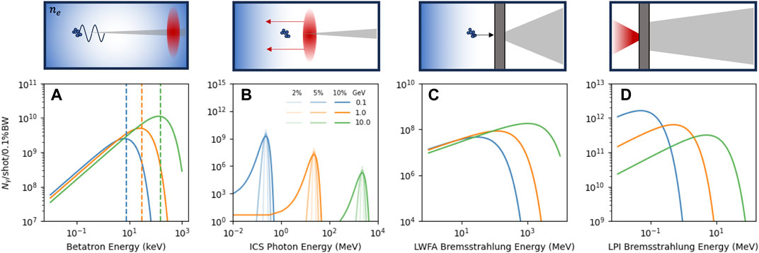
FIGURE 1. Schematic representation and example emission spectra for each X-ray generation mechanism by laser–plasma acceleration. (A) Betatron radiation, (B) inverse Compton scattering, (C) LWFA bremsstrahlung, and (D) direct target bremsstrahlung. Details of the calculations for each spectrum are given in the Supplementary Material. The three curves for each correspond to different laser–plasma conditions; in (A–C), these correspond to intensities and plasma densities that drive 100 MeV, 1 GeV, and 10 GeV electron bunches, respectively; in (D), this corresponds only to the intensity with the effective bremsstrahlung temperature scaling from 100 keV to 10 MeV. See Supplementary Material for further details.
In laser wakefield acceleration, the laser is focussed onto a gas target at low (
In laser–solid (overdense) interactions, the laser is again focussed on the target where electrons are ionised from the surface and accelerated up to MeV energies within the laser field before being driven into the target. Electrons accelerated by this mechanism generally have a broad Maxwell- or Boltzmann-like distribution of energies, and when interacting with the solid target, atoms produce a similarly broad distribution of laser–solid bremsstrahlung (Figure 1D) extending up to the peak energies of the electrons [4, 31–33]. The emission can be optimised by tuning the target material and thickness [34], lateral dimensions [4], and incident laser parameters [10, 33, 35]. The X-rays are typically more divergent than the laser-wakefield mechanisms but can still emanate from
This article outlines the primary approaches to spatially resolving the emission from laser-driven sources, a brief introduction to two distinct methods we can use to detect X-rays, and then a discussion on how to apply these techniques to each of the different sources discussed above. Here, we distinguish between detectors (i.e., the sensor/substrate/scintillator that records the incident X-ray radiation) and diagnostics which translate the measured signal into a useful characteristic of the beam. As there are numerous regimes laser-driven sources can produce, we consider that no single solution/detector will suffice and, instead, describe the necessary parameters across three case studies.
• High-resolution imaging with betatron radiation—3.1
• High-energy imaging with ICS and bremsstrahlung radiation—3.2
• High instantaneous flux with direct or proximity-focussing detectors—3.3
The expected photon parameters, where necessary, are taken from the scaling shown in Figure 1.
2 X-ray imaging approaches for laser-driven sources
With the adoption of higher-repetition high-power laser facilities, there has been considerable effort by the community to produce high-stability interactions. There are several recent proposals using LPI as the initial accelerator for FELs [36], ion beamlines [37], and compact ICS sources [26]. Maier et al. demonstrated significant improvements in the stability of laser-driven sources [38], and new facilities are being built and designed with mechanical and machine stability in mind, including active feedback to ensure long-term stability of the driving laser. However, especially during commissioning of new facilities, detectors and diagnostics need to be able to fully characterise the emission on a single-shot basis and not integrate or scan, assuming that the emission is constant. The requirement for single-shot acquisitions limits what diagnostic techniques are possible; for example, super-resolution methods [39] and single-event processing techniques [40] are not possible. This requirement is, therefore, an important factor in detector design for laser-driven sources.
2.1 Direct detection
Indirect and direct detection schemes are both useful in laser–plasma interactions. For direct-detection schemes, electrons within the substrate material are freed by incident radiation and swept towards an electronic readout. The total charge is then digitised by an ADC. High-grade Si, CdTe, and CZT semi-conductors are often used for direct detection. Detectors based on this mechanism have demonstrated sub-% energy resolution [41], large area [42–44], and X-ray energies of up to MeV [45]. Typically, these devices are operated in an integrating mode where the counts after the ADC correspond to an amount of charge deposited in the pixel. This can be interpreted as either the number of photons at a given energy or the energy of an individual photon. With the latter mode, it is, therefore, possible to retrieve spectroscopic information as well. Recent efforts with direct-detector systems aimed to increase the full frame rate of the camera beyond MHz repetition rates [46–48] for use in high average brilliance facilities. As the pulse duration for high-intensity laser sources is typically on the order of femto- to pico-seconds, increases in the frame rate of the detector have a limited impact on reducing the number of photons per frame. Instead, the area of the pixels must be considered to control the chance of interactions per pulse, the thickness of the substrate to tune the stopping power, and the full-well capacity of the readout to maximise the total energy that can be measured.
2.2 Indirect detection
In contrast to direct detection, indirect detection uses scintillators to convert the X-ray radiation into optical light that is then imaged with a standard optical camera and lens system. By tuning the scintillator and the optical relay, we can optimise detection as needed. The optical collector is either a lens or a fibre-optic plate. For imaging, the typical lenses considered are either microscope objectives or camera/machine vision lenses. Both options are compound lenses with many elements to correct aberrations or minimise distortion; however, the microscope objectives are generally of high numerical aperture with a magnification greater than unity, whereas machine vision lenses are typically of lower numerical aperture and demagnify the image onto the sensor. Critically, with either option, we must factor in the distance to the scintillator, (do), and opening aperture, D, of the optic to determine the effective numerical aperture (NA = D/2do) of the system with the magnification (Mo) to determine what the collection efficiency and resolution will be. There have been several studies on the relationship between these parameters [32, 49, 50]; in general, resolution and collection efficiency are inversely proportional. The resolution limit in the optically limited regime can be approximated as follows:
where p and q are fitting parameters determined by Koch et al. [49] and ℓ is the thickness of the scintillator. Throughout this article, we define the resolution as 90% of the integrated line-spread-function to mirror the work by Koch et al. [49]. This is notably larger than the full-width half-maximum, and so, features below the limits given here could still be visible—albeit at a lower contrast. The first term in Eq. 1 relates to the cumulative effects of diffraction and spherical aberrations stemming from the scintillator–air interface, and the second term is due to planes beyond the point of best focus contributing. We include the third term factoring in the pixel size dx and the optical magnification Mo to account for the limit in the low-magnification domain. In addition, this relationship holds assuming a pencil-like deposition throughout the scintillator. For the purposes of this discussion, we omit effects due to non-uniform attenuation throughout the scintillator [49] and large electron cascades with high-energy incident X-rays [51]. Assuming that we have a relatively thin (ℓ < λmfp) scintillator and a limited electron cloud radius, Eq. 1 sets the resolution at the detector plane, and so, by controlling the geometric magnification, Mg, the system resolution, can exceed this for samples or images. The signal detected in each pixel, however, is dependent on the attenuation of the scintillator, the conversion efficiency into optical photons κ, the collective power of the lens system, and the magnified area of pixels:
where QE(λ) is the quantum efficiency of the chosen sensor at the wavelength of emission, κ is the yield in photons per deposited energy for the scintillator material, n is the refractive index of the scintillator material (see Supplementary Material for collection efficiency derivation), and G a linear gain term to convert the number of photons to counts recorded by the sensor. This equation is similar in form to that determined by Cardarelli et al. [32]; however, the F-stop terms they used are replaced by terms for the effective numerical aperture and optical magnification directly. Where the deposited energy per mm2 is dependent on both the incident spectral shape, f(E), and the attenuation of the scintillator, to a first order, this can be expressed using the Beer–Lambert model for transmission as
where ρ is the density of the scintillator and σ is the attenuation cross section. Eq. 1 and Eq. 2 are both dependent on the length of the scintillator, ℓ, the numerical aperture of the lens system, and the optical magnification, resulting in a complex trade off of parameters between lens choices.
We demonstrate the calculation of both the signal and the resolution at the plane from parameters for typical systems, using both microscope objectives and camera lenses to image scintillators of different thicknesses, as shown in Figures 2A–C; we set the pixel size to 5 µm for each magnification and vary the numerical aperture of the lens to demonstrate the scaling. It is clear from evaluating Eq. 1 that the magnification and pixel size act as a hard limit on the resolution. When operating with high magnification, there becomes a significant dependence on the thickness of the scintillator and numerical aperture of the system. However, if we consider only the numerical aperture of the system, a clearer picture emerges—with a low numerical aperture; therefore, with a small angle being observed, there is little dependence on scintillator thickness, whereas with a high numerical aperture, the scintillator thickness becomes paramount to the achieved resolution. Figure 2D summarises how different commercially available optics vary in terms of achievable resolution and expected signal. The full dataset used is detailed in Supplementary Material. The data points assume a Gaussian X-ray distribution with a 100-keV centre and a full-width half-maximum of 40 keV.
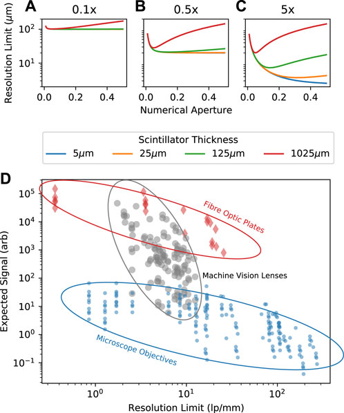
FIGURE 2. (A–C) Numerical calculation of Eq. 1 for p = 0.7, q = 0.28 from [49] for Mo = 0.1, 0.5, 5, respectively, and ℓ = 5–1025 μm. (D) Shows the determination of Eq. 1 and Eq. 2 for many indirect system configurations—the full dataset is included in Supplementary Data. Regions are highlighted outlining different schemes of detection, including microscope objectives and machine vision lenses.
3 Imaging case studies
In the following sections, we outline three distinct imaging challenges with laser-driven sources where advancements in detector characteristics would enhance the potential applications of laser-driven sources.
3.1 Single-shot high-resolution imaging with laser-driven betatron radiation
Laser-wakefield betatron sources have sub-micron source sizes [8]; however, typically, the smallest resolvable element achieved in experiments is much higher than this and is, instead, limited by the detector [52]. To achieve a high resolution at the detector plane, the best route is to use high-magnification objectives, as shown in Figure 2D; however, this limits the expected signal due to spreading over many pixels. Microscope objectives exhibit a general scaling between the numerical aperture and optical magnification of the form
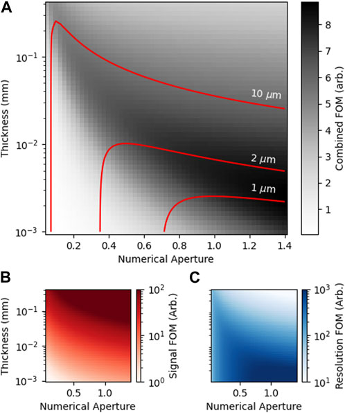
FIGURE 3. Figures of merit for the resolution and expected signal as a function of scintillator thickness and numerical aperture calculated at the plane (i.e., Mg = 1). (A) shows the signal per pixel divided by the resolution limit, i.e., Eq. 2 divided by Eq. 1, to highlight the best compromise between the signal and resolution; the solid curves over the top are contours demonstrating the limits for the achieved resolution. (B,C) show Eqs 1, 2 independently.
Betatron emission is divergent, albeit narrowly, (θ ≈ mRad), and so, the geometric magnification can increase the system resolution. This is also true of conventional X-ray tube sources; however, as their source area is typically large [53, 54] (excluding micro- and nano-focus systems [55]), the resolution is fundamentally limited by the extent of the source. The divergence of betatron emission combined with a small source opens up additional pathways to achieve sub-micron imaging, and we can look at the trade-offs between different optical systems by considering how the resolution and sensitivity vary as a function of each variable in 1–2.
Figure 4 shows the variation in the resolution and effective signal due to several parameters—numerical aperture (green), optical magnification (orange), geometric magnification (blue), and scintillator length (pink)—for a selection of microscope objectives, fibre-optic plates (FOPs), and high numerical aperture machine vision lenses. These three approaches represent distinct options for optical imaging. Generally speaking, microscope objectives have a numerical aperture between 0.1 and 0.5 and high magnification, fibre-optic plates of a high numerical aperture
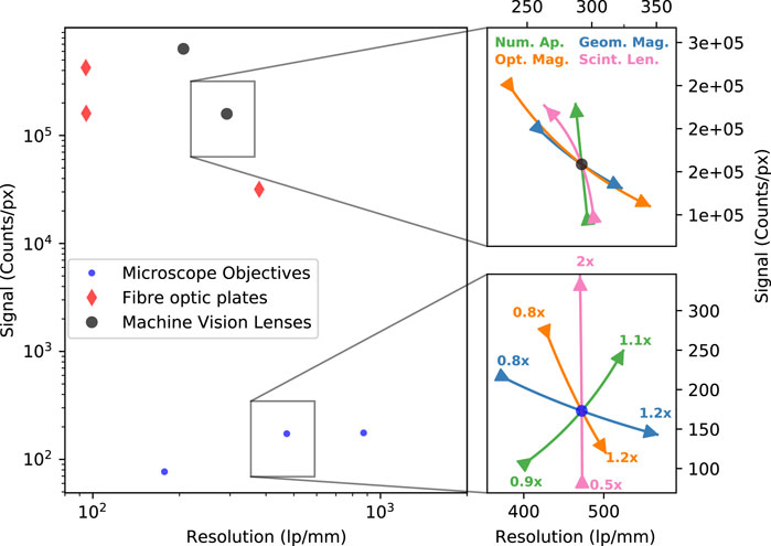
FIGURE 4. Expected signal (counts/px) and resolution (lp/mm) for microscope objectives, fibre-optic plates, and machine vision lenses, calculated by Eqs 1, 2. The subplots demonstrate the variation in performance due to numerical aperture (green), optical magnification (orange), geometric magnification (blue), and scintillator length (pink).
Interestingly, due to the difference in their initial values, increasing the numerical aperture for the highlighted machine vision lens results in a decrease in the expected resolution, leading to a significant increase in the highlight microscope objective. Conversely, if we consider increasing the thickness of the scintillator, we would observe an increase in the signal with no loss in resolution for the microscope objective, and yet, for the machine vision lens example, we observe a decrease in the resolution with minimal gains to the expected signal. Whilst these contradictions make it difficult to identify a general pattern, we note that the system resolution for the microscope objectives can be matched using the machine vision lenses but with a much greater signal. Since geometric magnification depends on the sample position rather than just the detector position, we can design systems to use lower optical magnification and increase the system resolution by reducing the sample position. The signal values are calculated assuming 7 × 10¹¹ photons with a divergence of 5 mRad and a critical energy of 50 keV—the parameters given for the example distribution in Figure 1A. For a single shot, it is clear that high-magnification objectives will result in a low signal-to-noise ratio, and so, many shots would likely need to be combined to achieve sufficient imaging quality.
In summary, to achieve a maximum signal with high-resolution imaging with betatron radiation, the best approach is to use relatively low optical magnification combined with high geometric magnification and keep the detector plane at the smallest distance from the source. In laser-wakefield acceleration (LWFA) experiments, the highly relativistic electron bunch must be deflected prior to interacting with the sample to minimise background contributions or damage to the sample. In practice, this sets a lower limit on the sample position (Z ≈ 1 m), and therefore, a compromise will need to be sought for different experimental configurations. In addition, objectives that exceed the
3.2 MeV imaging with ICS and laser-driven bremsstrahlung
It is pertinent to consider at this point the extreme case, where instead of a few hundred microns of the scintillator, we require thousands to ensure sufficient stopping power. Laser-driven sources can readily generate X-rays greater than 1 MeV via either inverse Compton sources or bremsstrahlung processes with energies extending up to 100 s of MeV for LWFA mechanisms. At these energies, the dominant X-ray attenuation mechanisms are no longer photo-electric absorption or scattering but nuclear and electronic-pair production [56]. This significantly alters the effects on resolution. No longer can we consider only the optical spreading determined by Koch et al. [49] (Eq. 1); we must now also factor in the lateral diffusion that occurs as the X-ray deposits energy through a scintillator. Solving these additional factors requires in-depth Monte Carlo simulations to be conducted. However, we can determine some useful bounds from the aforementioned equations. First, we consider that for a given energy, we can calculate the required thickness, ℓ, as a function of the desired absorption, i.e., ℓ = − log(T)/σρ. Second, we wish to calculate what the intrinsic (i.e., PSF limited) resolution would be for that thickness to inform how we select scintillator materials. The calculation of this is shown in Figure 5 for a plastic scintillator (CHO, e.g., EJ260, BC422q), YAG:Ce, BGO, and the high-Z and high-density GLO scintillator [57]. For each material, the effective resolution limit determined in Figure 5 could then be further refined by Monte Carlo simulations adding a fourth term to Eq. 1 to account for the radial spreading as the X-rays deposit their energy. The energy spreading in materials is also dependent on the density and effective-z, and so, whilst the scattering at higher energies will reduce the resolution, this effect will be reduced with higher-density materials [58, 59].
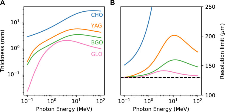
FIGURE 5. (A) Attenuation length for 10% absorption in each scintillator and (B) equivalent resolution limit for a scintillator of that length. Calculated via the NIST data tables [56] as a function of incident X-ray energy.
This scaling with density and atomic number underlines why research on the GLO scintillator is beneficial to high-energy X-ray imaging; the higher density is intrinsically linked to the minimum thickness and relative attenuation to high-energy X-rays. Consequently, continued research and development into exotic scintillators and their manufacture will greatly benefit radiography with high-energy X-rays [60].
3.3 High instantaneous X-ray flux imaging
In the previous cases, we considered an optical system to image the scintillation onto the sensor. However, the lens system introduces significant losses in the collection efficiency, and by switching to either direct detection, the sensor in contact with the scintillator, or the proximity focussing of FOPs, we can consider a far more efficient detection method for imaging the X-rays. With the losses from the optical system minimised, the detection efficiency can be calculated directly from NIST-XCOM data tables [56] and the Beer–Lambert law [61]. Figure 6 shows that the efficiency of stopping in the material can be up to 100% for betatron-like energies (∼50 keV) of X-rays for both scintillators (CsI and YAG) and thick direct-detection sensors such as CZT. The resolution for the direct detection is dependent on the pixel size and on PSF of the incident photon energy, whereas the FOP method is limited by the spreading in the scintillator, similar to Eq. 1.
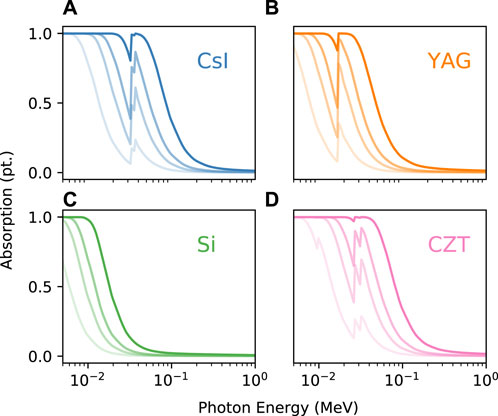
FIGURE 6. Absorption fraction for scintillators and direct-detector substrates, and the transparency of the line corresponds to the thickness of the layer—the order of increasing opacity corresponds to 20, 70, 150, and 500 µm thickness, respectively. Calculated via the NIST data tables [56] for (A) CSI, (B) YAG:Ce, (C) Si, and (D) CZT.
One desired application for such a detector is to measure the unattenuated beam in a single shot. The number of X-ray photons arriving per pixel is dependent on the emitted number, the divergence of the emission, and the solid angle subtended by each pixel. With these criteria and the photon distributions shown in Figure 1, we can generate the plot shown in Figure 7, showing the effective number of counts as a function of the incident photon intensity and the effective signal (Eq. 2) of a given detector. Here, we express the y-axis as Kdx2/z2, where K is the overall efficiency term from incident photons per pixel to counts. Expressing Eq. 2 like this provides a clear route to improving detector performance. Figure 7 shows the approximate dynamic ranges for various detectors [42, 62–64] available that can operate in the desired range; additionally, we include an “idealised” detector that operates with a high dynamic range similar to the MM-Pad diagnostics [64] but a pixel size of dx = 10 μm at a distance of z = 20 m and K = 10–4 [Counts/γx] to compensate. Additionally, we include a dashed line at 1 count/px to indicate the relative threshold for single-photon spectroscopy techniques. Current detector systems, at reasonable distances (
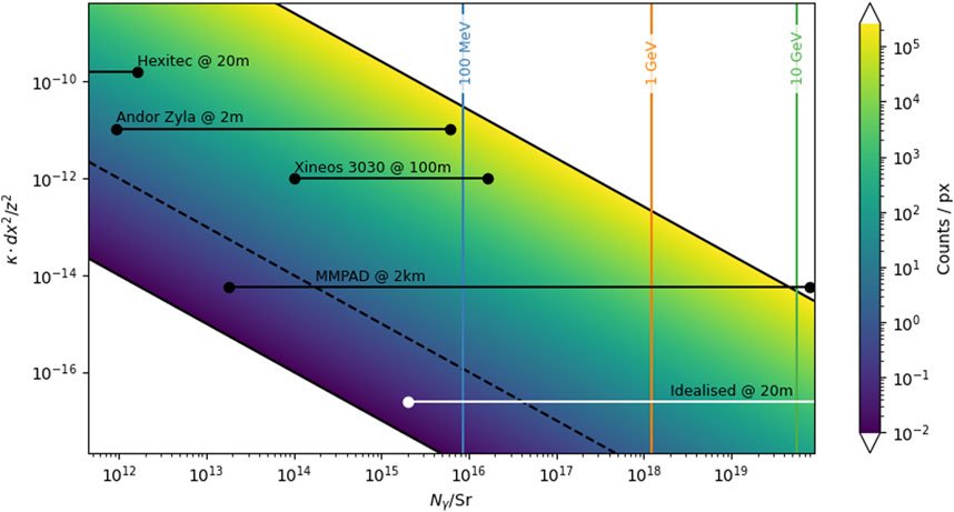
FIGURE 7. Calculated number of counts per pixel as a function of incident photons per Sr, and the relative pixel area (dx2/z2) and effective efficiency/gain (K) for a given detector system. The vertical lines correspond to the emission characteristics given in Figure 1A. The solid horizontal lines correspond to the effective dynamic range of the labelled detectors at representative distances, taking the background level and saturation point from the respective datasheets [42, 62–64].
4 Summary
Herein, we demonstrated, using analytical equations for resolution (Eq. 1) and signal (Eq. 2), approaches to X-ray imaging with laser-driven sources. The variety of X-ray energies and fluences poses a challenge to detectors but provides an opportunity for a wide variety of applications. Taking advantage of the diverging X-ray emission and the proximity to the source location, we can exploit geometric magnification to maximise the signal collected for a given resolution. With improvements to scintillator materials, we can design efficient scintillators for high-energy (
Data Availability Statement
The original contributions presented in the study are publicly available. This data can be found here: https://edata.stfc.ac.uk/handle/edata/945.
Author contributions
CDA: Conceptualization, Investigation, Methodology, Writing–original draft. GS: Conceptualization, and Writing–review and editing. SR: Conceptualization, Investigation, and Writing–review and editing. JP: Writing–review and editing. KF: Writing–review and editing. RG: Conceptualization, Investigation, Methodology, and Writing–review and editing. KW: Supervision, and Writing–review and editing. PR: Funding acquisition, Investigation, Supervision, and Writing–review and editing.
Funding
The author(s) declare financial support was received for the research, authorship, and/or publication of this article. This research was funded by the Strategic Priorities Fund and EPSRC grant EP/V049232/1.
Conflict of interest
The authors declare that the research was conducted in the absence of any commercial or financial relationships that could be construed as a potential conflict of interest.
Publisher’s note
All claims expressed in this article are solely those of the authors and do not necessarily represent those of their affiliated organizations, or those of the publisher, the editors, and the reviewers. Any product that may be evaluated in this article, or claim that may be made by its manufacturer, is not guaranteed or endorsed by the publisher.
Supplementary material
The Supplementary Material for this article can be found online at: https://www.frontiersin.org/articles/10.3389/fphy.2023.1286442/full#supplementary-material
References
1. Hamster H, Sullivan A, Gordon S, White W, Falcone R. Subpicosecond, electromagnetic pulses from intense laser-plasma interaction. Phys Rev Lett (1993) 71:2725–8. doi:10.1103/physrevlett.71.2725
2. Jaroszynski D, Bingham R, Brunetti E, Ersfeld B, Gallacher J, van Der Geer B, et al. Radiation sources based on laser–plasma interactions. Phil Trans R Soc A: Math Phys Eng Sci (2006) 364:689–710. doi:10.1098/rsta.2005.1732
3. Khachatryan A, Van Goor F, Boller KJ, Reitsma A, Jaroszynski D. Extremely short relativistic-electron-bunch generation in the laser wakefield via novel bunch injection scheme. Phys Rev Spec topics-Accelerators Beams (2004) 7:121301. doi:10.1103/physrevstab.7.121301
4. Armstrong C, Brenner C, Jones C, Rusby D, Davidson Z, Zhang Y, et al. Bremsstrahlung emission from high power laser interactions with constrained targets for industrial radiography. High Power Laser Sci Eng (2019) 7:e24. doi:10.1017/hpl.2019.8
5. Pirozhkov A, Esirkepov TZ, Pikuz T, Faenov AY, Ogura K, Hayashi Y, et al. Burst intensification by singularity emitting radiation in multi-stream flows. Scientific Rep (2017) 7:17968. doi:10.1038/s41598-017-17498-5
6. Park HS, Maddox BR, Giraldez E, Hatchett SP, Hudson LT, Izumi N, et al. High-resolution 17-75 keV backlighters for high energy density experiments. Phys Plasmas (2008) 15. doi:10.1063/1.2957918
7. Gruse JN, Streeter M, Thornton C, Armstrong C, Baird C, Bourgeois N, et al. Application of compact laser-driven accelerator x-ray sources for industrial imaging. Nucl Instr Methods Phys Res Section A: Acc Spectrometers, Detectors Associated Equipment (2020) 983:164369. doi:10.1016/j.nima.2020.164369
8. Köhler A, Couperus J, Zarini O, Jochmann A, Irman A, Schramm U. Single-shot betatron source size measurement from a laser-wakefield accelerator. Nucl Instr Methods Phys Res Section A: Acc Spectrometers, Detectors Associated Equipment (2016) 829:265–9. doi:10.1016/j.nima.2016.02.031
9. Albert F, Thomas AG. Applications of laser wakefield accelerator-based light sources. Plasma Phys Controlled Fusion (2016) 58:103001. doi:10.1088/0741-3335/58/10/103001
10. Armstrong C, Brenner C, Zemaityte E, Scott G, Rusby D, Liao G, et al. Bremsstrahlung emission profile from intense laser-solid interactions as a function of laser focal spot size. Plasma Phys Controlled Fusion (2019) 61:034001. doi:10.1088/1361-6587/aaf596
11. Wood J. Betatron radiation from laser wakefield accelerators and its applications. London: Imperial College London (2017). Ph.D. thesis.
12. Underwood C, Baird C, Murphy C, Armstrong C, Thornton C, Finlay O, et al. Development of control mechanisms for a laser wakefield accelerator-driven bremsstrahlung x-ray source for advanced radiographic imaging. Plasma Phys Controlled Fusion (2020) 62:124002. doi:10.1088/1361-6587/abbebe
13. Finlay O, Gruse J, Thornton C, Armstrong C, Baird C, Bourgeois N, et al. Characterisation of a laser plasma betatron source for high resolution x-ray imaging. Plasma Phys Controlled Fusion (2021) 63:084010. doi:10.1088/1361-6587/ac0fcf
14. Gibbon P. Short pulse laser interactions with matter: an introduction. Singapore: World Scientific (2005).
15. McKenna P, Neely D, Bingham R, Jaroszynski D. Laser-plasma interactions and applications. Cham: Springer (2013).
16. EPAC. Extreme photonics applications centre (2022). Available at: https://www.clf.stfc.ac.uk/Pages/EPAC.aspx (Accessed August 28, 2023).
17. Albert F, Lemos N, Shaw J, King P, Pollock B, Goyon C, et al. Betatron x-ray radiation in the self-modulated laser wakefield acceleration regime: prospects for a novel probe at large scale laser facilities. Nucl Fusion (2018) 59:032003. doi:10.1088/1741-4326/aad058
18. Lu W, Huang C, Zhou M, Mori W, Katsouleas T. Limits of linear plasma wakefield theory for electron or positron beams. Phys Plasmas (2005) 12. doi:10.1063/1.1905587
19. Lu W, Tzoufras M, Joshi C, Tsung F, Mori W, Vieira J, et al. Generating multi-gev electron bunches using single stage laser wakefield acceleration in a 3d nonlinear regime. Phys Rev Spec Topics-Accelerators Beams (2007) 10:061301. doi:10.1103/physrevstab.10.061301
20. Fourmaux S, Hallin E, Chaulagain U, Weber S, Kieffer J. Laser-based synchrotron x-ray radiation experimental scaling. Opt Express (2020) 28:3147–58. doi:10.1364/oe.383818
21. Kozlova M, Andriyash I, Gautier J, Sebban S, Smartsev S, Jourdain N, et al. Hard x rays from laser-wakefield accelerators in density tailored plasmas. Phys Rev X (2020) 10:011061. doi:10.1103/physrevx.10.011061
22. Chen S, Powers N, Ghebregziabher I, Maharjan C, Liu C, Golovin G, et al. Mev-energy x rays from inverse compton scattering with laser-wakefield accelerated electrons. Phys Rev Lett (2013) 110:155003. doi:10.1103/physrevlett.110.155003
23. Tsai HE, Wang X, Shaw JM, Li Z, Arefiev AV, Zhang X, et al. Compact tunable compton x-ray source from laser-plasma accelerator and plasma mirror. Phys Plasmas (2015) 22. doi:10.1063/1.4907655
24. Graves W, Bessuille J, Brown P, Carbajo S, Dolgashev V, Hong KH, et al. Compact x-ray source based on burst-mode inverse compton scattering at 100 khz. Phys Rev Spec Topics-Accelerators Beams (2014) 17:120701. doi:10.1103/physrevstab.17.120701
25. Sarri G, Corvan D, Schumaker W, Cole J, Di Piazza A, Ahmed H, et al. Ultrahigh brilliance multi-mev γ-ray beams from nonlinear relativistic thomson scattering. Phys Rev Lett (2014) 113:224801. doi:10.1103/physrevlett.113.224801
26. Eggl E, Dierolf M, Achterhold K, Jud C, Günther B, Braig E, et al. The munich compact light source: initial performance measures. J synchrotron Radiat (2016) 23:1137–42. doi:10.1107/s160057751600967x
27. Döpp A, Guillaume E, Thaury C, Gautier J, Andriyash I, Lifschitz A, et al. An all-optical compton source for single-exposure x-ray imaging. Plasma Phys Controlled Fusion (2016) 58:034005. doi:10.1088/0741-3335/58/3/034005
28. Cipiccia S, Wiggins S, Shanks R, Islam M, Vieux G, Issac R, et al. A tuneable ultra-compact high-power, ultra-short pulsed, bright gamma-ray source based on bremsstrahlung radiation from laser-plasma accelerated electrons. J Appl Phys (2012) 111. doi:10.1063/1.3693537
29. Dong K, Zhang T, Yu M, Wu Y, Zhu B, Tan F, et al. Micro-spot gamma-ray generation based on laser wakefield acceleration. J Appl Phys (2018) 123. doi:10.1063/1.4997142
30. Li S, Shen B, Xu J, Xu T, Yu Y, Li J, et al. Ultrafast multi-mev gamma-ray beam produced by laser-accelerated electrons. Phys Plasmas (2017) 24:093104. doi:10.1063/1.4996020
31. Giulietti D, Gizzi LA. X-ray emission from laser-produced plasmas. La Rivista Del Nuovo Cimento (1978-1999) (1998) 21:1–93. doi:10.1007/bf02874624
32. Cardarelli P, Paterno G, Di Domenico G, Consoli E, Marziani M, Andreotti M, et al. A gamma beam profile imager for eli-np gamma beam system. Nucl Instr Methods Phys Res Section A: Acc Spectrometers, Detectors Associated Equipment (2018) 893:109–16. doi:10.1016/j.nima.2018.03.023
33. Brenner C, Mirfayzi S, Rusby D, Armstrong C, Alejo A, Wilson L, et al. Laser-driven x-ray and neutron source development for industrial applications of plasma accelerators. Plasma Phys Controlled Fusion (2015) 58:014039. doi:10.1088/0741-3335/58/1/014039
34. Fiorini F, Neely D, Clarke RJ, Green S. Characterization of laser-driven electron and photon beams using the Monte Carlo code FLUKA. Laser Part Beams (2014) 32:233–41. doi:10.1017/S0263034614000044
35. Borm B, Khaghani D, Neumayer P. Properties of laser-driven hard x-ray sources over a wide range of laser intensities. Phys Plasmas (2019) 26. doi:10.1063/1.5081800
36. Assmann R, Weikum M, Akhter T, Alesini D, Alexandrova A, Anania M, et al. Eupraxia conceptual design report. Eur Phys J Spec Top (2020) 229:3675–4284. doi:10.1140/epjst/e2020-000127-8
37. Aymar G, Becker T, Boogert S, Borghesi M, Bingham R, Brenner C, et al. Lhara: the laser-hybrid accelerator for radiobiological applications. Front Phys (2020) 8:567738. doi:10.3389/fphy.2020.567738
38. Maier AR, Delbos NM, Eichner T, Hübner L, Jalas S, Jeppe L, et al. Decoding sources of energy variability in a laser-plasma accelerator. Phys Rev X (2020) 10:031039. doi:10.1103/physrevx.10.031039
39. Tian J, Ma KK. A survey on super-resolution imaging. Signal Image Video Process. (2011) 5:329–42. doi:10.1007/s11760-010-0204-6
40. Lu G, Fei B. Medical hyperspectral imaging: a review. J Biomed Opt (2014) 19:010901. doi:10.1117/1.jbo.19.1.010901
41. Jones L, Seller P, Wilson M, Hardie A. Hexitec asic—a pixellated readout chip for czt detectors. Nucl Instr Methods Phys Res Section A: Acc Spectrometers, Detectors Associated Equipment (2009) 604:34–7. doi:10.1016/j.nima.2009.01.046
42. Wilson M, Dummott L, Duarte DD, Green F, Pani S, Schneider A, et al. A 10 cm × 10 cm CdTe spectroscopic imaging detector based on the HEXITEC ASIC. J Instrumentation (2015) 10:P10011. doi:10.1088/1748-0221/10/10/p10011
43. Veale M, Seller P, Wilson M, Liotti E. Hexitec: a high-energy x-ray spectroscopic imaging detector for synchrotron applications. Synchrotron Radiat News (2018) 31:28–32. doi:10.1080/08940886.2018.1528431
44. Ballabriga R, Campbell M, Llopart X. Asic developments for radiation imaging applications: the medipix and timepix family. Nucl Instr Methods Phys Res Section A: Acc Spectrometers, Detectors Associated Equipment (2018) 878:10–23. doi:10.1016/j.nima.2017.07.029
45. Meuris A, Limousin O, Gevin O, Lugiez F, Le Mer I, Pinsard F, et al. Caliste hd: a new fine pitch cd (zn) te imaging spectrometer from 2 kev up to 1 mev. In: 2011 IEEE Nuclear Science Symposium Conference Record (IEEE); 30 October - 6 November 2010; Knoxville, Tennessee (2011). p. 4485–8.
46. Jones L, Bell S, Cline B, Gardiner T, Hart M, Prydderch M, et al. Spectroscopic x-ray imaging at mhz frame rates—the hexitecmhz asic. J Instrumentation (2022) 17:C10012. doi:10.1088/1748-0221/17/10/c10012
47. Zhang J, Andrä M, Barten R, Bergamaschi A, Brückner M, Chiriotti-Alvarez S, et al. Design and first tests of the gotthard-ii readout asic for the european x-ray free-electron laser. J Instrumentation (2021) 16:P04015. doi:10.1088/1748-0221/16/04/p04015
48. Allahgholi A, Becker J, Bianco L, Delfs A, Dinapoli R, Goettlicher P, et al. Agipd, a high dynamic range fast detector for the european xfel. J Instrumentation (2015) 10:C01023. doi:10.1088/1748-0221/10/01/c01023
49. Koch A, Raven C, Spanne P, Snigirev A. X-ray imaging with submicrometer resolution employing transparent luminescent screens. JOSA A (1998) 15:1940–51. doi:10.1364/josaa.15.001940
50. Martin T, Koch A. Recent developments in x-ray imaging with micrometer spatial resolution. J synchrotron Radiat (2006) 13:180–94. doi:10.1107/s0909049506000550
51. Iniewski K, Chen H, Bindley G, Kuvvetli I, Budtz-Jorgensen C. Modeling charge-sharing effects in pixellated czt detectors. In: 2007 IEEE Nuclear Science Symposium Conference Record (IEEE)vol. 6; 26 October 2007 - 03 November 2007; Hilton, Hawaiian (2007). p. 4608–11.
52. Cole J, Wood J, Lopes N, Poder K, Abel R, Alatabi S, et al. Tomography of human trabecular bone with a laser-wakefield driven x-ray source. Plasma Phys Controlled Fusion (2015) 58:014008. doi:10.1088/0741-3335/58/1/014008
53. Mattsson A. Some characteristics of a 600 kv flash x-ray tube. Physica Scripta (1972) 5:99–102. doi:10.1088/0031-8949/5/1-2/017
54. Hemberg O, Otendal M, Hertz HM. Liquid-metal-jet anode x-ray tube. Opt Eng (2004) 43:1682–8. doi:10.1117/1.1737787
55. Brunke O, Brockdorf K, Drews S, Müller B, Donath T, Herzen J, et al. Comparison between x-ray tube-based and synchrotron radiation-based μct. Dev X-ray tomography VI (Spie) (2008) 7078:260–71. doi:10.1117/12.794789
56. Berger MJ, Hubbell JH, Seltzer SM, Chang J, Coursey JS, Sukumar R, et al. XCOM: photon cross sections database. NIST Stand Reference Database (1998) 8:87–3597. doi:10.18434/T48G6X
57. Cherepy N, Seeley Z, Payne S, Swanberg E, Beck P, Schneberk D, et al. Transparent ceramic scintillators for gamma spectroscopy and mev imaging. Hard X-ray, Gamma-ray, neutron detector Phys XVII (Spie) (2015) 9593:74–80. doi:10.1117/12.862503
58. Ashley J, Ritchie R, Brandt W. Z 1 3 effect in the stopping power of matter for charged particles. Phys Rev B (1972) 5:2393–7. doi:10.1103/physrevb.5.2393
59. Wilson G, Dennison JR. Approximation of range in materials as a function of incident electron energy. IEEE Trans Plasma Sci (2012) 40:291–7. doi:10.1109/tps.2011.2176515
60. Derenzo S, Weber M, Bourret-Courchesne E, Klintenberg M. The quest for the ideal inorganic scintillator. Nucl Instr Methods Phys Res Section A: Acc Spectrometers, Detectors Associated Equipment (2003) 505:111–7. doi:10.1016/s0168-9002(03)01031-3
62. Andor zyla. Andor zyla datasheet (2023). Available at: https://andor.oxinst.com/assets/uploads/products/andor/documents/andor-zl41-wave-specifications.pdf (Accessed August 28, 2023).
63. Xineos. Xineos-3030hr datasheet (2022). Available at: https://www.teledynedalsa.com/download/3b835500-052b-469a-bfaf-5aac905fb2ec/ (Accessed August 28, 2023).
64. Philipp HT, Tate MW, Shanks KS, Purohit P, Gruner SM. High dynamic range cdte mixed-mode pixel array detector (mm-pad) for kilohertz imaging of hard x-rays. J Instrumentation (2020) 15:P06025. doi:10.1088/1748-0221/15/06/p06025
65. Rakowski R, Golovin G, O’Neal J, Zhang J, Zhang P, Zhao B, et al. Single-shot structural analysis by high-energy x-ray diffraction using an ultrashort all-optical source. Scientific Rep (2017) 7:16603. doi:10.1038/s41598-017-16477-0
Keywords: laser–plasma interactions, bremsstrahlung, betatron, inverse Compton scattering, laser wakefield, high-intensity laser, X-ray generation
Citation: Armstrong CD, Scott GG, Richards S, Patel JK, Fedorov K, Gray RJ, Welsby K and Rajeev PP (2023) X-ray detector requirements for laser–plasma accelerators. Front. Phys. 11:1286442. doi: 10.3389/fphy.2023.1286442
Received: 31 August 2023; Accepted: 16 November 2023;
Published: 21 December 2023.
Edited by:
Cornelia B. Wunderer, Helmholtz Association of German Research Centres (HZ), GermanyReviewed by:
Christopher John Hall, Australian Nuclear Science and Technology Organisation, AustraliaDavid Pennicard, Helmholtz Association of German Research Centres (HZ), Germany
Uddhab Chaulagain, ELI Beamlines, Czechia
Copyright © 2023 Armstrong, Scott, Richards, Patel, Fedorov, Gray, Welsby and Rajeev. This is an open-access article distributed under the terms of the Creative Commons Attribution License (CC BY). The use, distribution or reproduction in other forums is permitted, provided the original author(s) and the copyright owner(s) are credited and that the original publication in this journal is cited, in accordance with accepted academic practice. No use, distribution or reproduction is permitted which does not comply with these terms.
*Correspondence: Chris D. Armstrong, Y2hyaXMuYXJtc3Ryb25nQHN0ZmMuYWMudWs=
†Present address: K. Welsby, UK Research and Innovation, Swindon, United Kingdom
 Chris D. Armstrong
 G. G. Scott
 S. Richards
 J. K. Patel
 K. Fedorov1
 R. J. Gray
 P. P. Rajeev