 Shinichi Saito
- Center for Exploratory Research Laboratory, Research & Development Group, Hitachi, Ltd., Tokyo, Japan
Lie algebra is a hidden mathematical structure behind various quantum systems realised in nature. Here, we consider SU(2) wavefunctions for polarisation states of coherent photons emitted from a laser source, and discuss the relationship to spin expectation values with SO(3) symmetry based on isomorphism theorems. In particular, we found rotated half-wave-plates correspond to mirror reflections in the Poincaré sphere, which do not form a subgroup in the projected O(2) plane due to anti-hermitian property. This could be overcome experimentally by preparing another half-wave-plate to realise a pristine rotator in SU(2), which allows arbitrary rotation angles determined by the physical rotation. By combining another 2 quarter-wave-plates, we could also construct a genuine phase-shifter, thus, realising passive control over the full Poincaré sphere.
1 Introduction
Marius Sophus Lie introduced the concept of infinitesimal transformations as early as 1870s, which allowed classification and manipulation of complex matrices based on simple sets of Lie brackets, known as commutation relationships by physicists [1–6]. Lie algebra is especially powerful for applications in quantum mechanics, since the commutation relationships are essential to understanding fundamental properties of elementary particles [5–9]. One of the most simplest, but yet, non-trivial systems is a quantum 2-level system, described by the special unitary group of 2 dimensions, known as SU(2) [5, 7, 9].
These days, SU(2) systems are especially important for applications in quantum computing using qubits [10]. Various qubits are realised by charged-Cooper pairs in superconducting Josephson junctions [11–14], ions in optical traps [15, 16], single photons in silicon photonic circuits [17–20], and single electron spin in silicon transistors [21, 22] for realising Noisy Intermediate-Scale Quantum (NISQ) computing as a near term goal towards the fault-tolerant quantum computing in the long term [23]. These qubits are all based on elementary excitations with SU(2) symmetry, and thus, they are fragile against dissipation to environments surrounding microscopic qubits [24].
On the other hand, polarisation [25–29] is macroscopic manifestation of an spin state of photons with SU(2) symmetry [7–9, 30, 31]. The nature of polarisation was successfully discussed by Stokes and Poincaré [32, 33], even before the discovery of quantum mechanics [34–37]. Unlike early days of Stokes and Poincaré, today, modern quantum many-body theories are well-established [8, 38–43] and coherent laser sources are ubiquitously available in experiments [25–29, 44, 45]. Therefore, we have revisited to understand the nature of polarisation in a coherent state, and found that Stokes parameters, S = (S1, S2, S3), are expectation values of spin operators,
Here, we consider our SU(2) theory with regard to the relationship to Lie algebra especially for the relationship between the SU(2) state and the observed
2 Theory
2.1 SU(2) wavefunction for coherent photons
A microscopic consideration on spin states of coherent photons was made previously [47]. Here, we will review the results [7, 9, 25–29, 44, 45] from the perspective of Lie algebra [1–6]. Our starting point is to accept the principle that coherent photons from a laser are described by a macroscopic wavefunction with 2 degrees of freedom to represent the oscillating electro-magnetic fields perpendicular to each other. Therefore, the wavefunction contains 2 components, given by 2 complex number
The wavefunction must be normalised, such that we have 3 degrees of freedom, given by real number
We consider a generic transformation of the wavefunction, while we conceive the transformation corresponds to a quantum operation, realised simply by propagation of the electro-magnetic wave into HWPs, QWP, and so on. The transformation is given by a mapping made by a unitary group of 2-dimension,
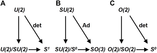
FIGURE 1. Isomorphic theorems for U (2), SU(2), and O(2). (A) Isomorphic mapping of U(2)/SU(2)≅S1 induced by a determinant. (B) Isomorphic mapping of SU(2)/S0≅SO(3) induced by an adjoint. (C) Isomorphic mapping of O (2)/SO(2)≅S0 induced by a determinant.
We consider an surjective mapping of determinant, det, from U(2) to
From a quantum mechanical point of view, above pedagogical mathematics simply means that the wavefunction to describe coherent photons is given by a product of orbital and spin wavefunctions, U(2)≅U(1) × SU(2), as
where z is the direction of propagation, t is time, θ is the polar angle, ϕ is the azimuthal angle on the Poincaré sphere [7, 9, 25–31, 44, 45, 47], and we have employed LR-bases [47].
In HV-bases, the wavefuntion is given by
where γ = 2α is the azimuthal angle measured from S1 in the Poincaré sphere, α is the auxiliary angle, and δ is the relative phase of the V-state against the H-state [47].
2.2 Lie group of SU(2) for quantum operations
According to the Lie group theory for SU(2), the rotation operator,
Pauli matrices, σi (i = 1, 2, 3), must satisfy the commutation relationships of Lie algebra
where ϵijk is the Levi-Civita in 3-dimensions, describing a complete anti-symmetric tensor. Pauli matrices also satisfy the anti-commutation relationships [2–4, 6].
As is always true for all operators in quantum mechanics [5–9], the rotation operator depends on the choice of bases. The rotation operator in LR-bases [25–29, 47] becomes.
where we have defined σLR = (σ1, σ2, σ3).
For the rotation of
On the other hand, the rotation operator in HV-bases becomes [25–29, 47].
where we have defined σHV = (σ3, σ1, σ2). Therefore, the choice of the bases will simply change the axis of rotation. For example, the rotation along the S1 axis is performed by σ3 in HV-bases [25–29, 47].
2.3 Applications of SU(2) theory to optical waveplates and rotators
An SU(2) theory is powerful to represent operations of optical waveplates and rotators on polarisation states [7, 9, 25–31, 44, 45, 47]. For example, the impact of the HWP, whose fast-axis/slow-axis (FA/SA) is aligned horizontally/vertically, is represented by setting the π-rotation as δϕ = π and the rotation axis along
From mathematical point of view, the origin of the spin rotation was coming from the difference of the phase-shifts in U(2) for orbital components among orthogonal polarisations upon propagation. For example, HWP gives different phase-shifts due to the difference of the wavelengths along FA and SA, since the refractive indices depend on the directions crystal orientations [7, 9, 25–31, 44, 45, 47]. In other words, the rotational symmetries are broken in optical waveplates and rotators, and it is effectively equivalent to apply a magnetic field to a magnet, which rotates a spin state. For a photon, there is no magnetic moment due to the lack charge, but the phase-shift can be precisely controlled by tuning the thickness of waveplates to account for the difference of the rotation upon propagation. In this sense, optical waveplates and rotators effectively work as a converter to transfer orbital degrees of freedom in U(2) to spin degrees of freedom in SU(2) (Figure 1A).
2.4 Mapping from SU(2) to SO(3)
It is well known that SU(2) is isomorphic to SO(3) in Lie group [2–9, 25–31, 47], and we discuss its consequence for coherent photons (Figure 1B). For simplicity, we consider LR-bases in this subsection, but the discussion is valid in other bases, simply by replacing axes. The structure constant of Lie algebra
for components i, j, k = 1, 2, 3, respectively (Figure 1B), which converts the bases from
such that the traceless complex 2 × 2 matrices, σi, in
for I = (I1, I2, I3) is angular momentum to generate a rotation [7, 9]. The traceless nature of
The exponential map from Lie algebra
for coherent photons. For example, the rotation along the S3 axis is given by
The commutation relationship of Eq. 6 in
This is apparent in the real space image of the wavefunction, since the SU(2) wavefunction is actually describing a complex electric field for orthogonal polarisation components in real space [25–29, 47]. Therefore, the 2π-rotation on the Poincaré sphere corresponds to the π-rotation in real space, which changes the sign of the electric field, as seen from Eq. 2. For example, suppose the original input beam is complete horizontally linear polarised state, |H⟩. The application of 2π-rotation could be achieved by 2 successive operations by HWPs, whose FAs are aligned to the same direction. This will change the input of |H⟩ to the output of −|H⟩, which is also horizontally polarised state, but has opposite in phase. Consequently, the point in the Poincaré sphere would not be changed, while the wavefunciton changes its sign. This change of the sign could be observed by an interference to the original input beam, which is bypassed from the original input. In fact, the phase-shift of π is ubiquitously employed in a Mach-Zehnder interferometer for high-speed optical switching [27]. In reality, of course, we must also consider the U (1) phase-shift, coming form the propagation in HWPs and the difference in optical path lengths, but it can be adjusted.
Mathematically, this is explained by isomorphism theorems (Figure 1B) [2–4, 6], since the kernel of the adjoint mapping from SU(2) to SO(3) is {1, − 1}≅S0 = {1, −1}. We confirmed this by putting δϕ = 2π in Eq. 4, which gives the non-trivial change of the sign by
2.5 Spin expectation values and Stokes parameters on the Poincaré sphere
Now, we have prepared to discuss the application of an SU(2) theory for photonics in more detail. For coherent photons, we can define the spin operator in SU(2) as
and we use
respectively, [47]. These average spin values are nothing but Stokes parameters [47], such that we confirm
The expectation values of
where the orientation angle is Ψ = ϕ/2, and the ellipticity angle is χ = π/4 − θ/2. These are also obtained simply by geometrical considerations of Stokes parameters on the Poincaré sphere [25–29, 47].
In general, we can consider the rotation operator independent on the representation [7, 9], which is given by.
where
independent on the choice of the bases.
We can check that a rotation of the polarisation state in SU(2) is actually corresponding to the rotation of the expectation values of spin in SO(3). Here, we briefly confirm this for optical rotators and phase-shifters in preferred bases. The optical rotator in LR-bases is given by the rotation along the S3 axis, which is given by
except for the U(1) phase factor (Figure 1A) for the orbital component upon propagation of a quartz rotator or a liquid-crystal rotator, for example, as a mean for the chiral rotation [25–29, 47]. Then, we consider how the spin part of the wavefunction, except for the orbital part, is changed upon the polarisation rotation. For seeing the change, it is straightforward to calculate the input state |input⟩ in LR bases,
is transferred to the output state, as
which indeed corresponds to rotate the state, ϕ → ϕ + Δϕ, by a rotator. In fact, by taking the quantum-mechanical expectation values of the output state, we obtain
The corresponding rotation in SO(3) can also be obtained by Mueller matrix of the rotator for coherent photons [28], which is actually
For the phase-shifter, on the other hand, it is easier to use HV-bases, and we obtain the phase-shifter operator for an optical waveplate, whose FA is aligned horizontally, as
where δsf is the expected phase-shift, and we have neglected the overall U(1) phase, as before. The operator, ΔHV(δsf), accounts for the rotation along the S1 axis, as
which indeed corresponds to a rotation of δ → δ + δsf. Consequently, the spin expectation values become
which can also be obtained by
where the corresponding Mueller matrix is.
2.6 Mirror reflection by rotated half-wavelength phase-shifter
HWPs, QWPs, and quartz rotators are useful optical components to control polarisation of photons [25–29], however, the amounts of rotation are usually fixed, determined by thickness of these plates. There are several ways to change the amount of rotations [25–29]. For example, an active control can be made by changing the electric field dynamically upon liquid crystal through transparent electrodes, which is used for applications in a liquid crystal display (LCD) [27–29, 44, 45]. Another method is to rotate a HWP to change the orientation angle of the polarisation ellipse [25–29, 44, 45]. Here, we will revisit the results for impacts on a rotated-HWP and discuss the consequences within a framework of Lie group.
We use LR bases to describe a rotated phase-shifter with the physical rotation angle of ΔΨ, and we obtain the operator [25–29, 44, 45, 47].
where the rotator along
The same result could be obtained by recognising the fact that we need an SU(2) rotation of δsf along the tilted direction of n = (cos (Δϕ), sin (Δϕ), 0) on the Poincaré sphere, and we obtain
For a HWP, we put δsf = π to obtain
which leads the output state of
Therefore, the impact of a rotated HWP is to change the polar angel, θ → θ′ = π − θ, and the azimuthal angle, ϕ → ϕ′ = 2Δϕ − ϕ. This corresponds to the Mueller matrix of
which is called as a pseudo rotator [28, 29]. The pseudo rotator works as a proper rotator for horizontally/vertically polarised state, since the output polarisation becomes
respectively with the rotation angle of 4 times, compared with the physical rotation angle. However, in general with the S3 component, the pseudo rotator does not represent a rotation at all. It actually represents a mirror reflection, as we shall see below.
For the S3 component, the pseudo rotation merely changes its sign, such that the left circulation becomes the right circulation, and vice versa. This could be understood from the last component of −1 in the block-diagonalised form of
For the change of the orientation angle, also known as the inclination angle to represent the direction of the primary axis of the polarisation ellipse, we consider the projection of SO(3) to its subgroup of O(2) in the S1 − S2 plane (Figure 2). Within this plane, the pseudo rotation corresponds to the mirror reflection of the original polarisation state (Figure 2A), which is a set of
in 2-dimensions. Interestingly, O−(2) does not form a proper sub-group within O(2), since it does not have an identity operator of 1. This means that a simple product law as a group like a ⋅ b = c for group elements, a, b, and c, do not necessarily hold. In particular, we see
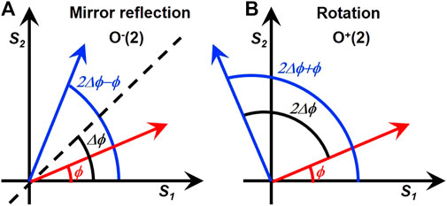
FIGURE 2. Impacts of O(2) = O−(2) ∪ O+(2) operations on polarisation states within the S1 − S2 plane. The red and blue arrows indicate input and output states, respectively. (A) Mirror reflection by a pseudo rotator in a set of O−(2). (B) Genuine rotation in a Lie group of O+(2) = SO(2).
On the other hand, the kernel of O(2) does form a sub-group of
in 2-dimensions, which is continuously connected to the identity,
We understand the pseudo rotator actually works as a mirror reflection within the S1 − S2 plane. On the other hand, the pseudo rotator is not a complete mirror reflection within the entire Poincaré sphere across the mirror plane, defined by a normal vector of (sin (Δϕ), − cos (Δϕ), 0), which should keep S3 constant. The pseudo rotator changes the sign of S3, such that the mirror plane for S3 is actually the S1 − S2 plane, whose normal vector is (0,0,1). As a result, the pseudo rotator could be decomposed of the mirror reflection in the S1 − S2 plane along the direction of (cos (Δϕ), sin (Δϕ), 0) for S1 and S2 components and another mirror reflection across the S1 − S2 plane for S3.
In order to use the pseudo rotator for realising desired polarisation states, we need to know the input polarisation state a priori before the application to the rotated-HWP, which limits the application, significantly. Similar to all other quantum systems, once measurements are taken place, the wavefunction collapses and we cannot recover the original wavefunction completely [7, 9]. It is ideal to construct a genuine rotator, which can rotate an expected amount, even without observing the input state.
2.7 Genuine rotator by two half-wave-plates
We can construct a genuine rotator, simply by introducing another HWP, whose FA is aligned horizontally, prior to the application of the pseudo rotator. In fact, the impact of successive operations of HWPs are calculated as.
which is indeed a genuine rotator of the angle of 4ΔΨ.
The same result can be confirmed in HV-bases as well. The rotated HWP operator in HV-bases becomes
such that we obtain
and therefore, we could construct a genuine rotation simply by 2 HWPs, while we must be careful for the amount of rotation of 4ΔΨ (Figure 2B). This simply means that the application of another HWP,
3 Experiments
3.1 Experimental set-up
The experimental set-up is shown in Figure 3. We used a frequency-locked distributed-feedback (DFB) laser diode at the wavelength of 1533 nm. The output power was 1.8 mW. The laser is coupled to a single mode fibre (SMF), and the beam is collimated to propagate in a free space, where rotating optical plates are located. The output beam is collected through a collimator to couple to a SMF. The polarisation states in SMFs were controlled by polarisation controllers, which apply stress to induce birefringence in SMFs. The stress was adjusted prior to experiments to examine the impact of rotating optical plates, inserted within the free space region of the set-up (Figure 3). The amount of rotation was physically adjusted by hand with a standard optical rotating element to accommodate wave-plates. A polarimeter was used to measure the polarisation state.
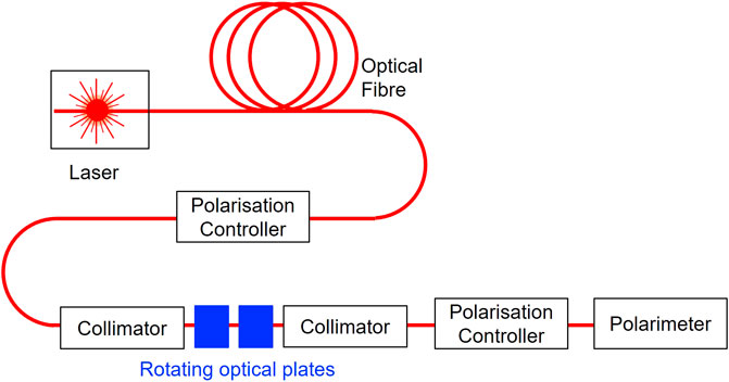
FIGURE 3. Experimental set-up. The frequency locked DFB laser diode at the wavelength (λ) of 1,533 nm was coupled to a single mode optical fibre. Polarisation controllers were used to adjust the polarisation state within the fibres. The rotating optical plates were inserted in a free space between collimator lenses. The output beam was characterised by a polarimeter.
3.2 Rotated quarter-wave-plates
First, we have examined the impacts of rotated QWPs [25–29, 44, 45, 47] on polarisation states (Figure 4). A QWP, whose FA is aligned horizontally, rotates the diagonally polarised state |D⟩ to the left circularly polarised state |L⟩ [25–29, 44, 45, 47], while it preserves the horizontally polarised state, |H⟩, and vertically polarised state, |V⟩, since it corresponds to rotate the state for 90° along the S1 axis. For the definition on the rotation, we followed the notation of [26, 47] to see the locus of the electric field, seen from a detector side in the right-handed coordinate. By changing the physical rotation angle, ΔΨ, of the QWP, the polarisation state would be continuously rotated with the maximum change of ±90°. Theoretical expectation values could be calculated by the SU(2) theory [25–29, 44, 45, 47]. For example, if the input is the horizontally polarised state, the spin expectation value S′ of the output state becomes
where the amount of rotation angle in the Poincaré sphere is defined to be Δϕ = 2ΔΨ, as before.
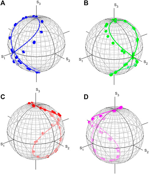
FIGURE 4. Polarisation states rotated in the Poincaré sphere by rotated quarter-wave-plates for inputs of (A) horizontally (blue), (B) diagonally (green), (C) vertically (red), and (D) anti-diagonally (magenta) polarised states. The lines are calculated results and dots are experimental results. Circles of latitude (parallels) and circles of longitude (meridians) are shown in every 10°.
The comparison between experiments and theoretical calculations are shown in Figure 4. We expected the deviation of the retardance from λ/4 with the amount of 0.006λ, which corresponds to the uncertainty of ±2.2°. Moreover, the amount of the rotation in the Poincaré sphere could be twice of that in the real space, as seen from Eq. 46. In fact, the maximum deviations of the order of ±10° were found. Nevertheless, the overall trends of experimental data are consistent with the theoretical expectations. The reason of this large deviation was coming from our choice of achromatic waveplates. For real applications, we should chose true zero-order waveplates, which must be designed to the wavelength of the laser. It is also encouraged to monitor actual variations of waveplates, since the retardance is sensitive to the thickness of a waveplate, which could vary within the manufacturing tolerance. For an application to require a high precision control of the polarisation state, additional waveplates might be required in order to compensate the deviation, which will add another design complexity.
We have also examined the impacts of rotated HWPs, and confirmed expected behaviours on the changes of the polarisation states as a pseudo rotator. In particular, it did not change the polarisation states for the inputs of |H⟩ and |V⟩, if we set the FA of the HWP to the horizontal direction, while the inputs of the diagonally polarised state
3.3 Genuine rotator by 2 half-wave-plates
Next, we have set 2 half-wave-plates, one fixed to align the FA horizontally and the other one to allow rotations, as discussed above to realise a genuine rotator. The experimental results and theoretical comparisons are shown in Figures 5, 6. We see that the polarisation states are rotating 4 times upon the physical 1 rotation of the HWP, as discussed theoretically. The important evidence as a genuine rotator was confirmed at ΔΨ = 0, which conserved the polarisation states, such that the input polarisations were preserved, regardless of the inputs. For Figure 5, we used |H⟩ and |V⟩ as inputs, and we observed essentially the same results with those of a pseudo rotator, since the π-rotation along S1 did not affect |H⟩ and |V⟩. On the other hand, |D⟩ and |A⟩ were reversed by a pseudo rotator (not shown) at ΔΨ = 0. As shown in Figure 6, we confirmed that a genuine rotator did not affect the inputs of |D⟩ and |A⟩ at ΔΨ = 0. This is essentially coming from
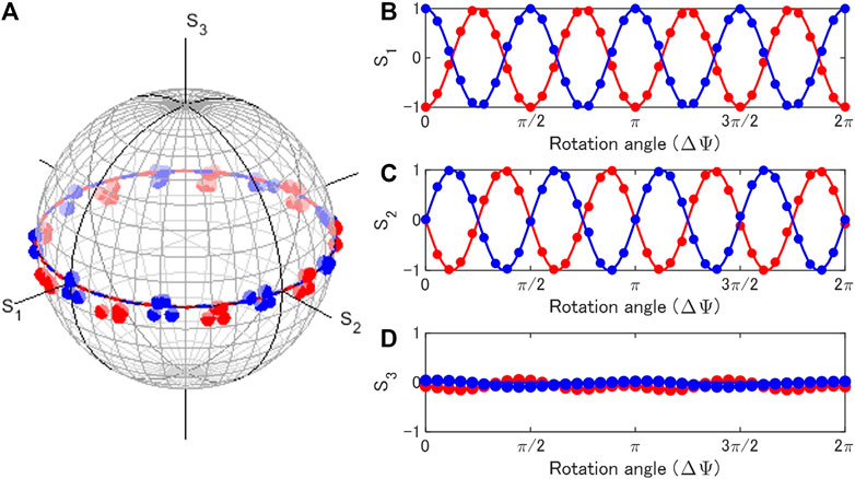
FIGURE 5. Rotator operation by rotated half-wave-plates for inputs of horizontally (blue) and vertically (red) polarised states. One plate was rotated, while another one was fixed. (A) Trajectories of polarisation states in the Poincaré sphere. (B) S1, (C) S2, and (D) S3 changed upon the physical rotation (ΔΨ) of the half-wave-plate.
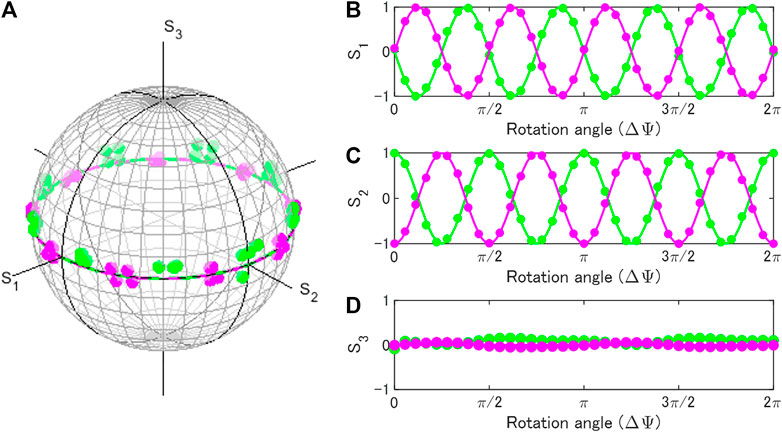
FIGURE 6. Rotator operation by rotated half-wave-plates for inputs of diagonally (green) and anti-diagonally (magenta) polarised states. One plate was rotated, while another one was fixed. (A) Trajectories of polarisation states in the Poincaré sphere. (B) S1, (C) S2, and (D) S3 changed upon the physical rotation (ΔΨ) of the half-wave-plate.
In the genuine rotator, we can control the amount of rotation in the Poincaré sphere solely by controlling the physical amount of rotation irrespective of the input state, which was remarkably different from the behaviour of a pseudo rotator. Both genuine and pseudo rotators did not affect the S3 component such that the inputs of linearly polarised state were still linearly polarised states upon the propagation of these rotators.
3.4 Comparison between genuine and pseudo rotators
On the other hand, if the inputs contain the S3 component, the difference of the impacts between genuine and pseudo rotators was outstanding. In Figure 7, we show the comparison of output states controlled by these rotators for the same input of the polarisation state at (S1, S2, S3) = (0.71, 0, 0.71). As expected for a pseudo rotator, we confirmed the sign of the S3 component was changed [28, 29, 47], which means the direction of oscillation in the polarisation ellipse was reversed to be the clockwise rotation from the anti-clockwise rotation. This is inevitable, since the pseudo rotation is coming from a π-rotation along some rotation axis in the S1 − S2 plane. Therefore, S3 must change its sign upon the rotation. As a result, the pseudo rotator cannot recover the original input state, no matter how much we rotate the HWP. Mathematically, this was from the fact that pseudo rotators do not form a group, and O−(2) does not include the identity operation.
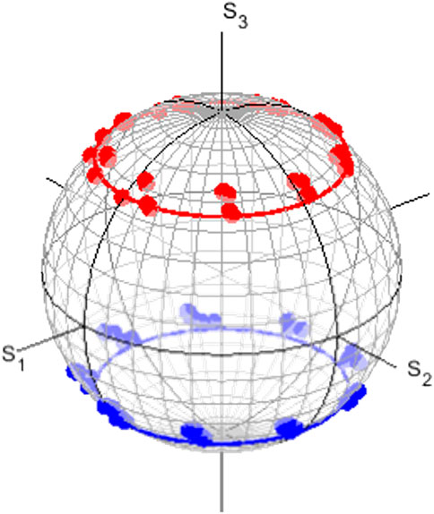
FIGURE 7. Comparison of genuine (red) and pseudo (blue) rotators on polarisation states in the Poincaré sphere. The polarisation state of the input was located at (S1, S2, S3) = (0.71, 0, 0.71). The pseudo rotator changed the sign of S3, such that the chirality is reversed. The genuine rotator preserved the value of S3, such that the rotation plane includes the original point.
On the other hand, a genuine rotator is composed of 2 rotations, one is a π-rotation along the S1 axis and the other is a successive π-rotation along some rotation axis in the S1 − S2 plane. Therefore, S3 is kept constant upon the total 2π-rotation, while S1 and S2 components are rotated along the S3 axis. Consequently, the genuine rotator change the polarisation state within the plane, which includes the original point for the input polarisation state. Ultimately, this is the evidence that the genuine rotators indeed form a subgroup of SO(2), which must include the identity operator of 1 to maintain the original state.
In order to confirm the further evidence that a genuine rotator is different from a pseudo rotator, we consider 2 successive operations of these rotators. We prepared 2 rotators and the input beam was successively passing through these operators, and we observed the output polarisation state.
For genuine rotators, we expect
which means that genuine rotation form a group, such that 2 successive operations could be considered to be equivalent to 1 operation of the added rotation angle. In order to confirm this, we needed to prepare 4 HWPs. FA of the first one was aligned horizontally, the second one was rotated for ΔΨ, and FA of the third one was aligned horizontally, and the forth one was rotated for ΔΨ. The experimental results are shown in Figure 8. We confirmed 8 rotations of the polarisation states in the Poincaré sphere. We admit the noticeable fluctuations of experimental data due to physical rotations of 2 HWPs, but they were well below the potential maximum deviations of ∼±44° due to 8 times rotations, compared with the physical rotation.
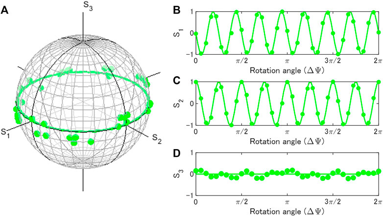
FIGURE 8. Successive operations of genuine rotators in the Poincaré sphere. The input state was diagonally polarised. 2 rotators rotated twice of the rotation for 1 rotator. 8 rotations are realised by physical 1 rotation for each rotator. (A) Trajectories of polarisation states in the Poincaré sphere. (B) S1, (C) S2, and (D) S3 changed upon the physical rotation (ΔΨ) of the half-wave-plate.
On the other hand, 2 successive operations of pseudo rotators should bring the input state back, because a mirror reflection works as an inverse of itself, as
which immediately leads
Therefore, 2 rotators of the same rotation angle cannot change the polarisation state. In order to confirm this, we needed 2 HWPs, which were rotated at the same angle. As shown in Figure 9, we confirmed the polarisation states of output beams were not significantly affected. Therefore, pseudo rotators are essentially made of mirror reflections, such that 2 successive operations cannot change the input state.
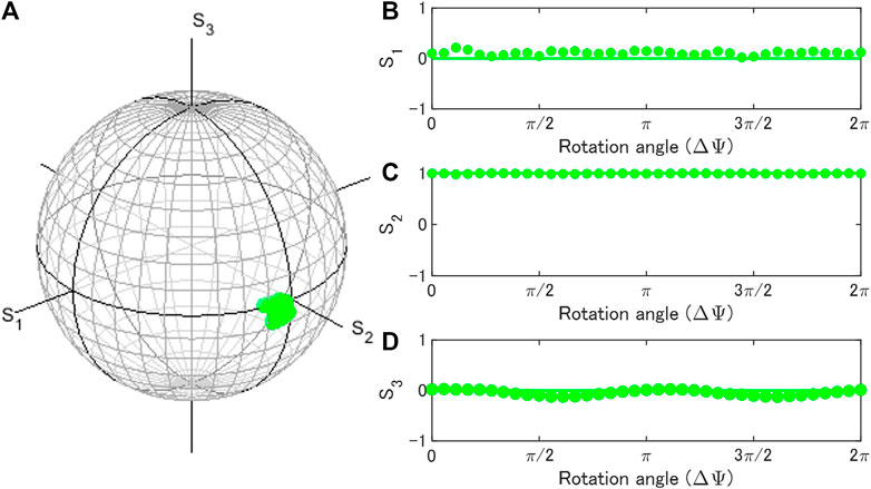
FIGURE 9. Successive operations of pseudo rotators in the Poincaré sphere. The input state was diagonally polarised. This corresponds to 2 mirror reflections, which cannot change the polarisation state. (A) Trajectories of polarisation states in the Poincaré sphere. (B) S1, (C) S2, and (D) S3 changed upon the physical rotation (ΔΨ) of the half-wave-plate.
Here, we have proved that our genuine rotator could rotate the polarisation state without observing the polarisation state, while the pseudo rotator could not form a group, as it works as a mirror reflection. One of the most important potential application of our genuine rotator will be polarisation controls for photonic quantum computing based on polarisation qubits [10]. For applications to qubits, measurement process significantly affects the quantum states of qubits due to the collapse of wavefunction [7, 9, 10]. If the genuine rotator is applied to polarisation qubits, single qubit operations will be achieved without observing the polarisation state.
3.5 Genuine phase-shifter realised by half-wave and quarter-wave plates
Now, we could establish how to make a genuine rotator solely by 2 HWPs. Next, we will show how to construct a genuine phase-shifter, whose phase-shift angle is determined by a physical rotation of the HWP. The phase-shifter corresponds to the rotation, in the plane which include the S3 axis, which can be achieved by inserting 2 QWP before and after the genuine rotation in the S1 − S2 plane. In order to rotate in the S1 − S3 plane, we need to apply the QWP, whose FA is aligned vertically. This will bring the S3 axis to the S2 axis by the 90° clock-wise rotation along the S1 axis. Then, we can apply the genuine rotator to rotate within the S1 − S2 plane by using 2 HWPs. Finally, we use another QWP, whose FA is aligned horizontally, to bring the rotated axis back to the original one by the 90° anti-clock-wise rotation along the S1 axis. The amount of the rotation is determined by the rotated HWP, which is the third plate among 4 plates, such that the amount of the phase-shift angle is expected to be 4 times that of the physical rotation angle, as for a genuine rotator.
Experimental results on the inputs of |H⟩ and |V⟩ are shown in Figure 10. We confirm that the phase-shift vanishes without the rotation (ΔΨ = 0), such that the genuine phase-shifter is continuously connected to the identity operator of 1. This is consistent with the fact that the phase-shifter forms a sub-group in SU(2). As we rotate the HWP, the polarisation states rotated 4 times along the meridian across the Poincaré sphere upon the physical rotation of 1 time.
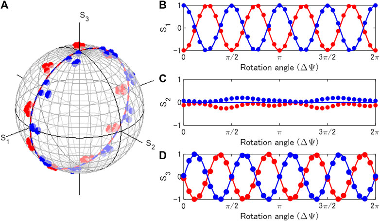
FIGURE 10. Phase-shifter operation by rotating a half-wave-plate for inputs of horizontally (blue) and vertically (red) polarised states. 2 quarter-wave-plates were inserted before and after the rotator operation. (A) Trajectories of polarisation states in the Poincaré sphere. (B) S1, (C) S2, and (D) S3 changed upon the physical rotation (ΔΨ) of the half-wave-plate.
In order to rotate in the S2 − S3 plane, which is more standard for a phase-shift, we need to apply the QWP, whose FA is rotated 45° for the clock-wise direction. This will bring the S3 axis to the S1 axis by the 90° clock-wise rotation along the S2 axis. Then, we can apply the genuine rotator to rotate within the S1 − S2 plane by using 2 HWPs, as before. Finally, we use another QWP, whose FA is rotated 45° for the anti-clock-wise direction to bring the rotated axis back. This can be confirmed by calculating.
which means that we can realise the proper phase-shifter,
As shown in Figure 11, we confirm the expected phase-shift for the inputs of |D⟩ and |A⟩. Again, we confirmed that the phase-shift vanished without the rotation (ΔΨ = 0). The rotation in the S2 − S3 plane is quite useful especially for considering HV-bases. By utilising this technique, one can easily realise arbitrary phase-shift in a laboratory solely by physical rotation of the wave-plates using widely available HWPs and QWPs.
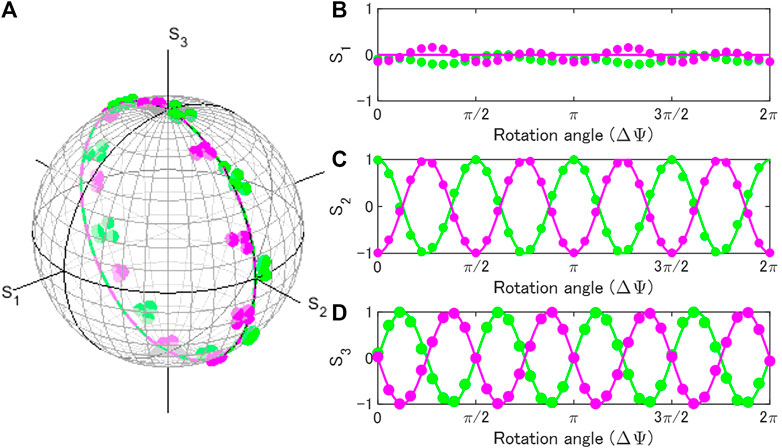
FIGURE 11. Phase-shifter operation by rotating a half-wave-plate for inputs of diagonally (green) and anti-diagonally (magenta) polarised states. 2 quarter-wave-plates were inserted before and after the rotator operation. (A) Trajectories of polarisation states in the Poincaré sphere. (B) S1, (C) S2, and (D) S3 changed upon the physical rotation (ΔΨ) of the half-wave-plate.
The proposed genuine phase-shifter requires 4 waveplates, which is actually redundant, compared with 3 waveplates of the SU(2) gadget [51, 52], which is widely used for controlling polarisation states. In fact, it was established that 2 QWPs, followed by 1 HWP, are minimum number of waveplates to realise arbitrary SU(2) rotations [51, 52]. However, in order to realise a target rotation by the SU(2) gadget, it is required to calculate 3 angles of the waveplates for physical rotations, from 3 Euler angles [51, 52]. Instead, we do not need to calculate the rotation angle for our proposed genuine phase-shifter, since the phase-shift is directly determined by the physical rotation angle of the second HWP. This corresponds to realise an arbitrary phase-shift, instead of just π and π/2 for HWP and QWP, respectively, while keeping the rotation axis along S1, S2, or any other preferred directions, determined by the fixed QWPs, which is too complicated to realise by the SU(2) gadget. Usually, arbitrary phase-shifts are realised by active optical devices, such as liquid crystal or Lithium Niobate (LN) Electro-Optic (EO) modulators [28, 29, 44, 45]. The proposed phase-shifter corresponds to a simple alternative solution as a passive optical component, using 1 extra plate, compared with the SU(2) gadget [51, 52].
4 Discussions and conclusion
We discuss mathematical and physical reasons why we could construct a rotator and a phase-shifter, simply from combinations of HWPs and QWPs for the perspective of Lie group. As we have shown, the crucial point was to construct a subgroup SO(2) in SO(3) for spin expectation values of S, represented by
This rotation keeps the S3 component, such that the rotation plane is perpendicular to the S3 axis. In LR bases, this corresponds to maintain θ, while changing ϕ to rotate along the parallel in the Poincaré sphere. In the original SU(2) operator for the wavefunction, this was achieved by
Therefore, the 2-dimensional rotator is equivalent to
which works as a continuous basis [53], and the application of the U(1) rotation is given by
where the subscript of 3 stands for the rotation along the S3 axis, such that we obtain
Consequently, we confirm that the rotator merely corresponds to the mapping of ϕ → ϕ + 2Δϕ by the U(1) subgroup embedded in SU(2), and the rotation along S3 was achieved without affecting θ. The U(1) wavefunction could be embedded to the original SU(2) wavefunction in LR-bases as
but we must be careful for using the U(1) representation of
Practically, the rotation angle in the Poincaré sphere is determined by the physical rotation angle, such that we can continuously change the 1-parameter in U(1) by hands. Therefore, our rotator is physical realisation of U(1) for polarisation states.
Having constructed a rotator, it was straightforward to construct a phase-shifter, since we just needed to change the rotation axis by a QWP before the rotation, and bring back to the original coordinate by a 90°-rotated QWP from the first one after the rotation. This corresponds to realise an SU(2) rotation
for i = 1, 2, 3, and
which is suitable for LR bases. We must be careful on the amount of expected rotation in the Poincaré sphere is 4 times of that of the physical rotation of HWPs. We can also construct.
which is suitable for HV-bases.
We can also realise an Euler rotation [9].
for an arbitrary rotation in the 3-dimensional Poincaré sphere.
An advantage to use our Poincaré rotator is the ability that we can perform expected amount of rotation along the preferred axis without knowing the polarisation state in the input. As we have shown theoretically and confirmed experimentally, the Poincaré rotator works as a subgroup of U(1) upon the physical rotation, which means that the polarisation state can be controlled continuously changed from the input state. To guarantee this, it was very important to make sure that the operation contains the identity operation of 1 to make sure that the operation is realised by a continuous change of the operation from 1. This is crucial requirement for a Lie group [1–6], since Lie group and Lie algebra were constructed from group theoretical considerations near the operation around identities. Consequently, by using Poincaré rotator, we can apply the same amount of rotation, regardless of the polarisation states of the input beam, which was not possible in a pseudo rotator configuration. This characteristic would be useful for some applications to require a certain rotation without measuring the input state.
A Poincaré rotator is also useful to control the orbital angular momentum of photons [54]. The left and right vortexed states are orthogonal each other, such that they form SU(2) states [54–63]. A superposition states with these vortices can be controlled by a Poincaré rotator by adjusting the phase and amplitudes [54].
For the measurements of polarisation states, we have used the standard polarimetry, using HWP and QWP [25–29, 32, 33, 44, 45]. Upon successful demonstrations of the proposed Poincaré rotator, there is a potential that we can replace a standard polarimetry set-up with the Poincaré rotator together with a detector and a polariser. In this case, we can reduce the number of detectors from 4 to 1, since we can use the Poincaré rotator to allow arbitrary rotations in SU(2). However, we need 6 waveplates for our Poincaré rotator, instead of 2 waveplates in the standard polarimetry, such that the set-up is obviously redundant.
So far, all theoretical considerations and experimental results are consistent with the assessment that coherent photons have an SU(2) symmetry and we can apply a standard quantum mechanical prescription for an SU(2) state to understand the polarisation states [7, 9, 25–33, 44, 45, 47–50]. We think that the physical origin of the macroscopic quantum coherence of polarisation is coming from the broken symmetry upon lasing threshold [47–50], such that we can treat coherent photons as a simple 2-level system to account for their spin expectation values. The impacts of optical wave-plates could be explained by corresponding rotations in the Poincaré sphere [7, 9, 25–33, 44, 45, 47–50]. We have shown that the underlying mathematical foundation for polarisation states is deeply routed in Lie group and Lie algebra. By applying isomorphism theorems [2–4, 6] for coherent photons, we confirmed the relationship between SU(2) rotation for the wavefunction and the resultant SO(3) rotation for spin expectation values. We also found that a pseudo rotator made by a rotated half-wave-plate is describing mirror reflections and we could convert it by introducing another half-wave-plate to realise a genuine rotator by 2 plates. This corresponds to converting O−(2) to O+(2)≅SO(2) by σ3. By changing the rotation axes by quarter-wave-plates, we could also make a genuine phase-shifter, such that the arbitrary rotations can be realised by a proposed passive Poincaré rotator. The implication of this work is a perspective that we can utilise the SU(2) degree of freedom in coherent photons for potential quantum technologies.
Data availability statement
The raw data supporting the conclusion of this article will be made available by the author, without undue reservation.
Author contributions
The author confirms being the sole contributor of this work and has approved it for publication.
Funding
This work is supported by JSPS KAKENHI Grant Number JP 18K19958.
Acknowledgments
The author would like to express sincere thanks to Prof I. Tomita for continuous discussions and encouragements.
Conflict of interest
SS is employed by Hitachi, Ltd.
Publisher’s note
All claims expressed in this article are solely those of the authors and do not necessarily represent those of their affiliated organizations, or those of the publisher, the editors and the reviewers. Any product that may be evaluated in this article, or claim that may be made by its manufacturer, is not guaranteed or endorsed by the publisher.
References
1. Stubhaug A. The mathematician Sophus Lie - it was the audacity of my thinking. Berlin: Springer-Verlag (2002).
3. Hall BC. Lie groups, Lie algebras, and representations; an elementary introduction. Switzerland: Springer (2003).
6. Georgi H. Lie algebras in particle Physics: From isospin to unified theories (Frontiers in Physics). Massachusetts: Westview Press (1999).
10. Nielsen M, Chuang I. Quantum computation and quantum information. Cambridge: Cambridge University Press (2000).
11. Nakamura Y, Pashkin YA, Tsai JS. Coherent control of macroscopic quantum states in a single-cooper-pair box. Nature (1999) 398:786–8. doi:10.1038/19718
12. Koch J, Yu TM, Gambetta J, Houck AA, Shuster DI, Majer J, et al. Charge-insensitive qubit design derived from the cooper pair box. Phys Rev A (2007) 76:042319. doi:10.1103/PhysRevA.76.042319
13. Schreier JA, Houck AA, Koch J, Schuster DI, Johnson BR, Chow JM, et al. Suppressing charge noise decoherence in superconducting charge qubits. Phys Rev B (2008) 77(R):180502. doi:10.1103/PhysRevB.77.180502
14. Arute F, Arya K, Babbush R, Bacon D, Bardin JC, Barends R, et al. Quantum supremacy using a programmable superconducting processor. Nature (2019) 574:505–10. doi:10.1038/s41586-019-1666-5
15. Bruzewicz CD, Chiaverini J, McConnell R, Saga JM. Trapped-ion quantum computing: Progress and challenges. Appl Phys Rev (2019) 6:021314. doi:10.1063/1.5088164
16. Pino JM, Dreiling JM, Figgatt C, Gaebler JP, Moses SA, Allman MS, et al. Demonstration of the trapped-ion quantum CCD computer architecture. Nature (2021) 592:209–13. doi:10.1038/s41586-021-03318-4
17. O’Brien J, Pryde G, White A, Ralph TC, Branning D. Demonstration of an all-optical quantum controlled-NOT gate. Nature (2003) 426:264–7. doi:10.1038/nature02054
18. Peruzzo A, McClean J, Shadbolt P, Yung MH, Zhou XQ, Love PJ, et al. A variational eigenvalue solver on a photonic quantum processor. Nat Commun (2014) 5:4213. doi:10.1038/ncomms5213
19. Silverstone JW, Bonneau D, O’Brien JL, Thompson MG. Silicon quantum photonics. IEEE J Sel Top Quan Electron. (2016) 22:390–402. doi:10.1109/JSTQE.2016.2573218
20. Takeda S, Furusawa A. Universal quantum computing with measurement-induced continuous-variable gate sequence in a loop-based architecture. Phys Rev Lett (2017) 119:120504. doi:10.1103/PhysRevLett.119.120504
21. Lee N, Tsuchiya R, Shinkai G, Kanno Y, Mine T, Takahama T, et al. Enhancing electrostatic coupling in silicon quantum dot array by dual gate oxide thickness for large-scale integration. Appl Phys Lett (2020) 116:162106. doi:10.1063/1.5141522
22. Xue X, Patra B, v Dijk Jpg , Samkharadze N, Subramanian S, Corna A, et al. CMOS-based cryogenic control of silicon quantum circuits. Nature (2021) 593:205–10. doi:10.1038/s41586-021-03469-4
23. Preskill J. Quantum computing in the nisq era and beyond. Quantum (2018) 2:79. doi:10.22331/q-2018-08-06-79
24. Caldeira AO, Leggett AJ. Influence of dissipation on quantum tunneling in macroscopic systems. Phys Rev Lett (1981) 46:211–4. doi:10.1103/PhysRevLett.46.211
25. Born M, Wolf E. Principles of optics. Cambridge: Cambridge University Press (1999). doi:10.1017/9781108769914
27. Yariv Y, Yeh P. Photonics: Optical electronics in modern communications. Oxford: Oxford University Press (1997).
28. Gil JJ, Ossikovski R. Polarized light and the mueller matrix approach. London: CRC Press (2016). doi:10.1201/b19711
30. Jones RC. A new calculus for the treatment of optical systems i. description and discussion of the calculus. J Opt Soc Am (1941) 31:488–93. doi:10.1364/JOSA.31.000488
31. Fano U. A Stokes-parameter technique for the treatment of polarization in quantum mechanics. Phy Rev (1954) 93:121–3. doi:10.1103/PhysRev.93.121
32. Stokes GG. On the composition and resolution of streams of polarized light from different sources. Trans Cambridge Phil Soc (1851) 9:399–416. doi:10.1017/CBO9780511702266.010
33. Poincaré JH. In: G Carré, editor. Théorie mathématique de la lumière, Tome 2. Paris (1892). Available at: https://gallica.bnf.fr/ark:/12148/bpt6k5462651m.
34. Plank M. On the theory of the energy distribution law of the normal spectrum. Verhandl Dtsch Phys Ges (1900) 2:82–90. doi:10.1016/B978-0-08-012102-4.50013-9
35. Einstein A. Concerning an heuristic point of view toward the emission and transformation of light. Ann Phys (1905) 17:132–48. doi:10.1002/andp.19053220607
37. Dirac PAM. The quantum theory of the electron. Proc R Sco Lond A (1928) 1117:610–24. doi:10.1098/rspa.1928.0023
38. Abrikosov AA, Gorkov LP, Dzyaloshinski IE. Methods of quantum field thoery in statistical Physics. New York: Dover (1975).
40. Weinberg S. The quantum theory of fields: Foundations volume 1. Cambridge: Cambridge University Press (2005).
42. Parker MA. Physics of optoelectronics. Boca Raton: Taylor & Francis (2005). doi:10.1201/9781420027716
43. Altland A, Simons B. Condensed matter field theory. Cambridge: Cambridge University Press (2010).
45. Pedrotti FL, Pedrotti LM, Pedrotti LS. Introduction to optics. New York: Pearson Education (2007).
46. Saito S, Tomita I, Sotto M, Debnath K, Byers J, Al-Attili AZ, et al. Si photonic waveguides with broken symmetries: Applications from modulators to quantum simulations. Jpn J Appl Phys (2020) 59:SO0801. doi:10.35848/1347-4065/ab85ad
48. Saito S. Quantum commutation relationship for photonic orbital angular momentum. arXiv (2023). doi:10.48550/arXiv.2303.17116
49. Saito S. Spin and orbital angular momentum of coherent photons in a waveguide. arXiv (2023). doi:10.48550/arXiv.2303.17129
50. Saito S. Dirac equation for photons: Origin of polarisation. arXiv (2023). doi:10.48550/arXiv.2303.18196
51. Simon R, Mukunda N. Minimal three-component SU(2) gadget for polarization optics. Phys Lett (1990) 143:165–9. doi:10.1016/0375-9601(90)90732-4
52. Schilling U, v Zanthier J, Agarwal GS. Measuring arbitrary-order coherences: Tomography of single-mode multiphoton polarization-entangled states. Phys Rev A (2010) 81:013826. doi:10.1103/PhysRevA.81.013826
54. Saito S. Poincaré rotator for vortexed photons. Front Phys (2021) 9:646228. doi:10.3389/fphy.2021.646228
55. Allen L, Beijersbergen MW, Spreeuw RJC, Woerdman JP. Orbital angular momentum of light and the transformation of Laguerre-Gaussian laser modes. Phys Rev A (1992) 45:8185–9. doi:10.1103/PhysRevA.45.8185
56. Padgett MJ, Courtial J. Poincaré-sphere equivalent for light beams containing orbital angular momentum. Opt Lett (1999) 24:430–2. doi:10.1364/OL.24.000430
57. Holleczek A, Aiello A, Gabriel C, Marquardt C, Leuchs G. Classical and quantum properties of cylindrically polarized states of light. Opt Exp (2011) 19:9714–36. doi:10.1364/OE.19.009714
58. Milione G, Sztul HI, Nolan DA, Alfano RR. Higher-order Poincaré sphere, Stokes parameters, and the angular momentum of light. Phys Rev Lett (2011) 107:053601. doi:10.1103/PhysRevLett.107.053601
59. Naidoo D, Roux FS, Dudley A, Litvin I, Piccirillo B, Marrucci L, et al. Controlled generation of higher-order Poincaré sphere beams from a laser. Nat Photon (2016) 10:327–32. doi:10.1038/NPHOTON.2016.37
60. Liu Z, Liu Y, Ke Y, Liu Y, Shu W, Luo H, et al. Generation of arbitrary vector vortex beams on hybrid-order Poincaré sphere. Photon Res (2017) 5:15–21. doi:10.1364/PRJ.5.000015
61. Erhard M, Fickler R, Krenn M, Zeilinger A. Twisted photons: New quantum perspectives in high dimensions. Light: Sci Appl (2018) 7:17146. doi:10.1038/lsa.2017.146
62. Andrews DL. Symmetry and quantum features in optical vortices. Symmetry (2021) 13:1368. doi:10.3390/sym.13081368
Keywords: Stokes parameters, Poincaré sphere, polarisation, spin angular momentum, SU(2), coherent state, Poincaré rotator
Citation: Saito S (2023) SU(2) symmetry of coherent photons and application to Poincaré rotator. Front. Phys. 11:1225419. doi: 10.3389/fphy.2023.1225419
Received: 19 May 2023; Accepted: 23 June 2023;
Published: 07 July 2023.
Edited by:
Jianming Wen, Kennesaw State University, United StatesReviewed by:
Xuanying Lai, The University of Texas at Dallas, United StatesKangkang Li, Peking University, China
Zhen-Biao Yang, Fuzhou University, China
Copyright © 2023 Saito. This is an open-access article distributed under the terms of the Creative Commons Attribution License (CC BY). The use, distribution or reproduction in other forums is permitted, provided the original author(s) and the copyright owner(s) are credited and that the original publication in this journal is cited, in accordance with accepted academic practice. No use, distribution or reproduction is permitted which does not comply with these terms.
*Correspondence: Shinichi Saito, c2hpbmljaGkuc2FpdG8ucXRAaGl0YWNoaS5jb20=