 Sohail Nadeem
 Rehan Akber
 Shahah Almutairi2
 Hassan Ali Ghazwani
95% of researchers rate our articles as excellent or good
Learn more about the work of our research integrity team to safeguard the quality of each article we publish.
Find out more
ORIGINAL RESEARCH article
Front. Phys. , 22 August 2022
Sec. Interdisciplinary Physics
Volume 10 - 2022 | https://doi.org/10.3389/fphy.2022.959168
This article studies fluid dynamics and convection of the geothermal system. Earthquakes cause faults. Fault zones come up with the pathways for fluid convection. These paths have different characteristics and space distribution, causing the challenge to investigate the geothermal system. The cavity considered in the study is normally found in energy reservoirs. An unsteady, incompressible, and laminar flow along with convection is studied. The finite element method (FEM) is operated to study the flow and heat transfer governed by continuity equations, Navier-Stokes equations, and temperature equations. These equations are tackled with the finite element method. The streamlines and isothermal contours for the problem under discussion are displayed in the Results section. It is observed that the Nusselt number and velocity of the fluid increase with the increased Grashof number.
According to geophysics, earthquakes cause faults. Faults can be considered as planar or curved fractures in rock due to which the rock displaces from its place to the other side of the fracture. Their length starts from centimeters and varies up to kilometers. They move either slowly or rapidly. Faults moving rapidly release more energy. The conglomeration of parallel faults forms a fault zone. Faults can be classified into three types: (I) tensional faults, in which the block of rock moves vertically upwards to the fault; (II) compressional faults, in which the block of rock moves vertically downwards to the fault; and (III) strike-slip faults, in which the block of rock moves along the fault horizontally [1–3].
The energy accumulation of radioactive material disintegration results in the expansion of material in the earth’s interior with the increase of temperature. The expansion may produce tensional fault zones. Faults without magma are filled with mantle gas and supercritical fluid. Fluids in their supercritical states have very high molar volume, and very low density and conductivity. These fluids exhibit strong fluidity and low viscosity. According to hydrothermal ore-forming theory, hydrothermal fluid in the middle-lower crust can move to the upper crust where it changes to its normal state. Also
Energy that transfers from system to system as a consequence of temperature difference is called heat. Heat transfer is a process to determine such energy transfers. It is very significant for physicists, mathematicians, engineers, and researchers. It effects the fluid flow and due to its remarkable applications in different engineering fields, biological processes, industrial mechanisms, and geothermal studies, its study is of great significance [6–17].
Conduction, convection, and radiation are three different ways in which heat transfer is classified. Heat transfer through molecular collision is called conduction, heat transportation between a fluid adjacent to a surface and that surface is called convection, and heat transfer through electromagnetic waves is called radiation. Convection is either natural convection or forced convection. Forced convection is driven by external body forces, and natural convection is simply a result of buoyancy force [18–30].
Fluid flow is an analysis to study the behavior of fluids and their interaction with their surroundings. The flow of a fluid may be turbulent or laminar. In laminar flow, parallel layers form during the flow such that these layers do not disturb each other, while flows are more chaotic in the case of turbulent flows. On the other hand, flow is steady if fluid properties do not depend on time; otherwise they are unsteady. Fluid flow is visualized using streamlines, streaklines, and pathlines. Most problems in fluid dynamics are too complex to solve analytically. To solve such complex problems, numerical methods are implemented with the help of computer simulation. This field of study is called computational fluid dynamics (CFD). In this paper, the subsurface hydrothermal fluid flow has been studied using computational techniques [31–43].
A cavity having an inlet and an outlet is considered to be in the fault zone. A viscous and incompressible fluid enters through the inlet on one side and leaves the cavity on the other side. A metal piece in a rectangular shape is considered inside the cavity. The article studies unsteady and laminar fluid flow through the cavity and heat transfer during natural convection between the metal piece and the fluid.
The prevailing equations are worked out followed by Boussinesq assumption. Numerical results are acquired by the use of the Galerkin finite element method (FEM) [44–54]. The influences of changing the involved parameters in the study on velocity and isothermal contours are presented. The physical properties of heat transfer and flow are exhibited using isotherms, temperature distribution, and streamlines. Further, the average Nusselt number is evaluated which analyzes heat transfer rate from the rod.
A 2D unsteady, incompressible, laminar, and natural convective flow inside a cavity is carried out in the study. A metal piece is placed at the middle of the considered cavity. The walls of the cavity are thermally active and are at a higher temperature
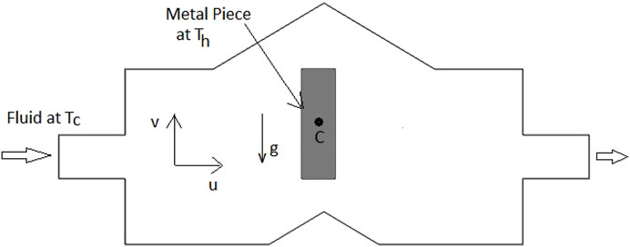
FIGURE 1. Geometry of cavity formed by fault.
The fluid’s thermophysical characteristics are defined to be fixed. For natural convection, the density can be defined according to the Boussinesq approximation; this variation is expressed in the momentum equation (Eq. 4 below). The density can be related to temperature linearly by the relation defined in Eq. 1:
In the energy equation, the radiation heat transfer and joule heating are disregarded. The governing equations [55, 56] depending on the above assumptions taken are as follows:
Initial conditions for the under-discussion problem are as follows:
For
Boundary conditions are as follows:
For
where n is normal to the surface.
The system of governing equations given by Eqs. 2–10 is reduced to dimensionless form by the use of dimensionless variables given as follows:
After this parametrization, Eqs. 2–5 become the following:
with initial conditions as the following:
For
and boundary conditions as the following:
For
where
Since analytical methods to solve the system of equations given by Eqs. 11–19 fail for complicated cases, numerical techniques are used to obtain the solution. As discussed before, the Galerkin finite element method is applied to solve the system of Eqs. 11–19. The pressure term is penalized by the virtue of the penalty parameter
Using Eq. 20 in Eqs. 12 and 13, wegetthe following:
Weight functions are used to give the weak formulation of Eqs. 14, 21, and 22. The weak formulations of these equations for a triangular element
where the subscript
Using FEM, we approximate the functions U (X, Y,
where
The above integrals are evaluated by numerical integration.
Thus, we get a linear system of equations and is tackled using Newton-Raphson form:
The above system of equations is solved for every iteration. Here d represents the iterative index, R (
The Nusselt number measures the rate of heat transfer from the heated rod. It is calculated as follows:
where n is normal to the plane.
At the vertical wall of the rod, it is defined as follows:
And at the horizontal wall, it is defined as follows:
The expressions that calculate the average Nusselt number over vertical and horizontal sides of the rod will be given by the following:
respectively.
A triangular mesh of 3,930 elements was used to study the problem numerically as shown in the Figure 2.
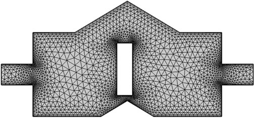
FIGURE 2. Meshing of the cavity.
The grid independent test is necessary to ensure the accuracy of the results. For this, the Nusselt number is calculated for a different number of triangular mesh elements. It is noted that the percentage error in the Nusselt number for mesh elements 3,001 is about 0.01% as compared with the refined mesh of 3,930 triangular elements. Therefore, the refined mesh of 3,930 triangular elements is used to explore the present problem. Table 1 shows different values of the Nusselt number for different mesh elements at Re = 700 and Gr = 5×10³.
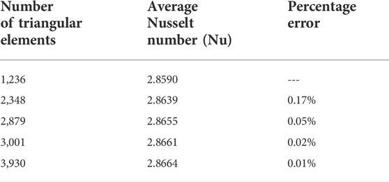
TABLE 1. Grid independent test.
In this portion, the flow and heat transfer through the cavity formed due to the fault have been shown graphically for various parameters using COMSOL Multiphysics. In Figure 3, the Reynolds number is kept constant at 700 and the Grashof number is varied, and in Figure 4, the Reynolds number is kept fixed at 1,000 and the Grashof number is varied. It can be seen that the flow pattern is varied slightly for greater Grashof numbers, but velocity increases remarkably for Gr
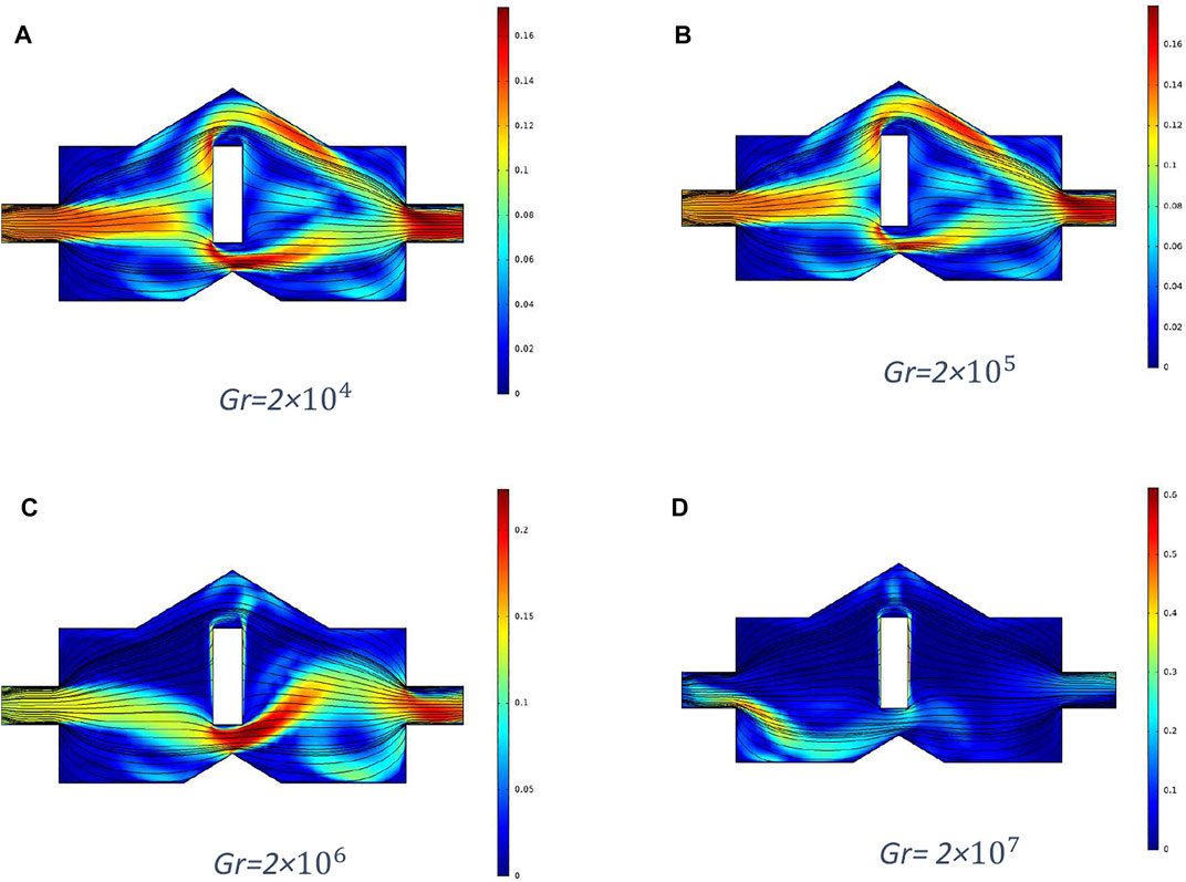
FIGURE 3. Streamlines at Re = 700 and at different Grashof numbers.
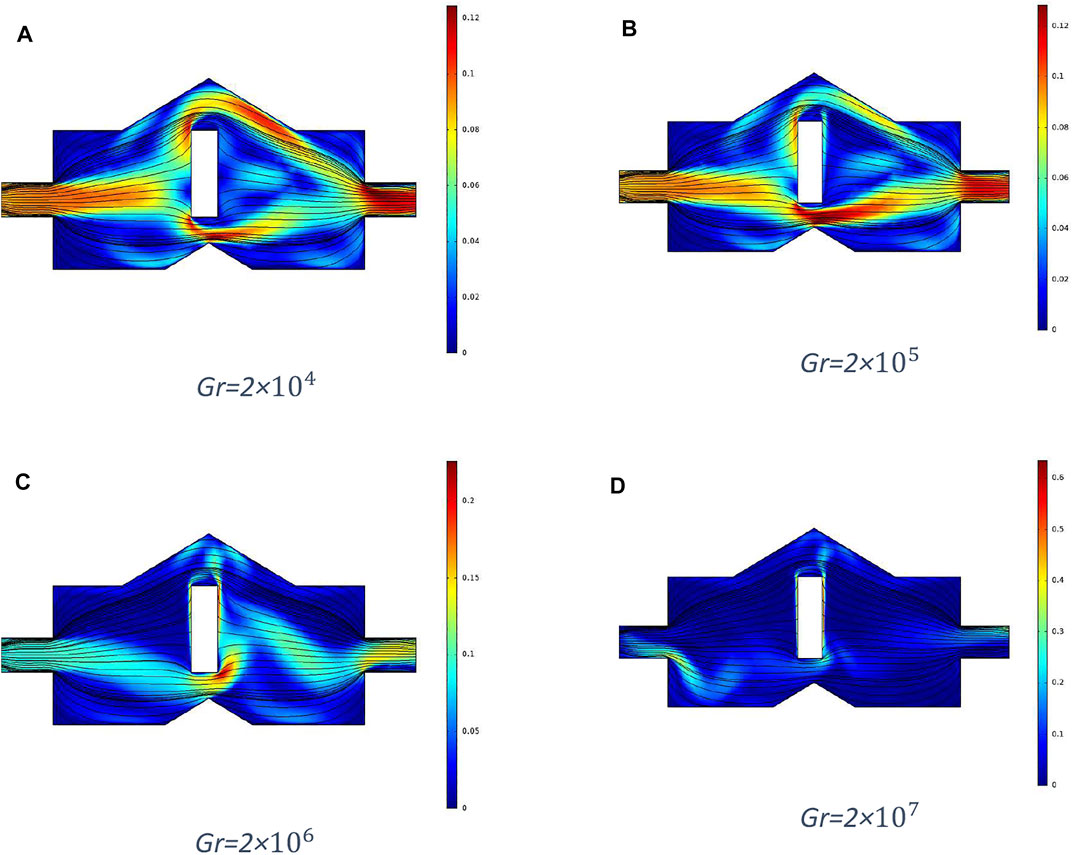
FIGURE 4. Streamlines at Re = 1,000 and at different Grashof numbers.
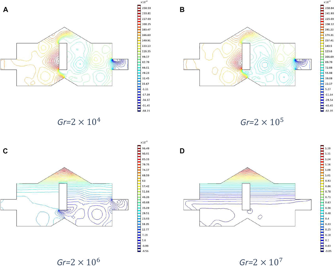
FIGURE 5. Pressure Variation at Re = 700 and at different Grashof Number.
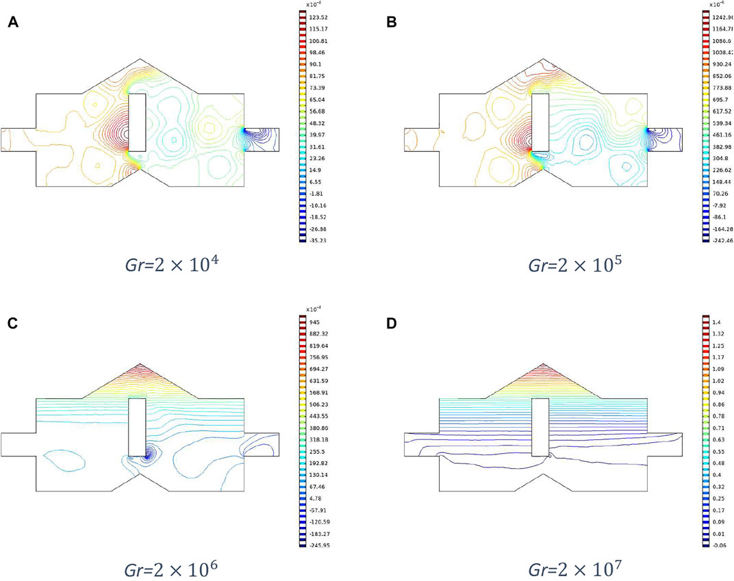
FIGURE 6. Pressure Variation at Re = 1,000 and at different Grashof Number.
Moreover, from Figures 7–10, significant variation can be observed in the convection dominant region. Figures 7 and 8 represent temperature distributions and isotherms, respectively at different Grashof numbers and fixed Reynolds number 700, and Figures 9 and 10 show temperature distributions and isotherms, respectively for different Grashof numbers and fixed Reynolds number 1,000. The temperature distribution becomes more uniform, and isotherms spread more within the cavity for Gr
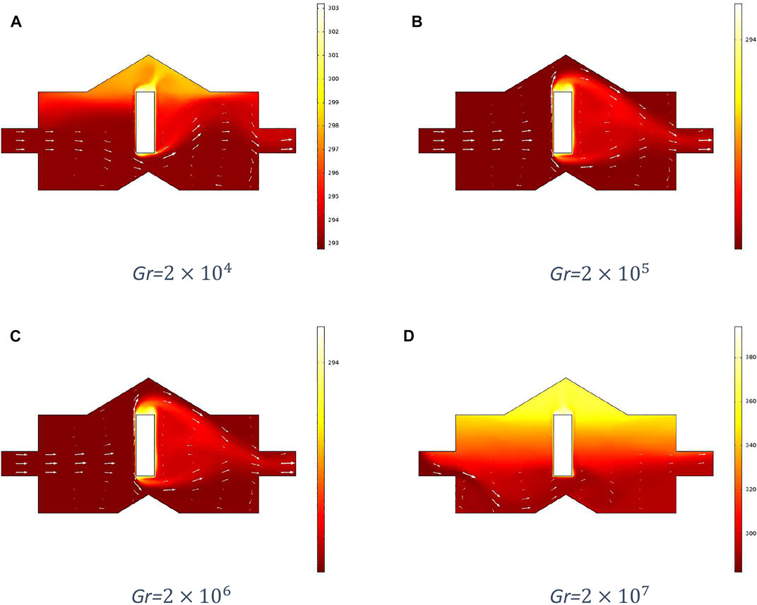
FIGURE 7. Temperature distribution at Re = 700 and at different Grashof Number.
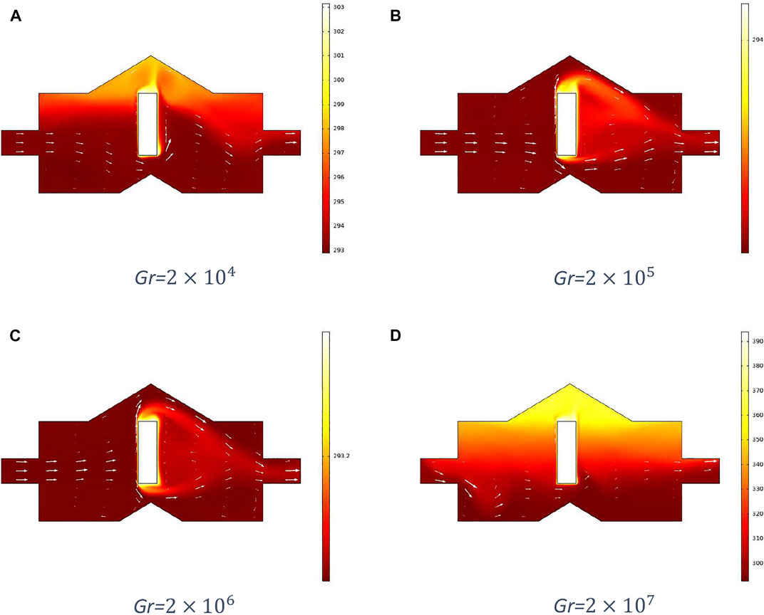
FIGURE 8. Temperature distribution at Re = 1,000 and at different Grashof Number.
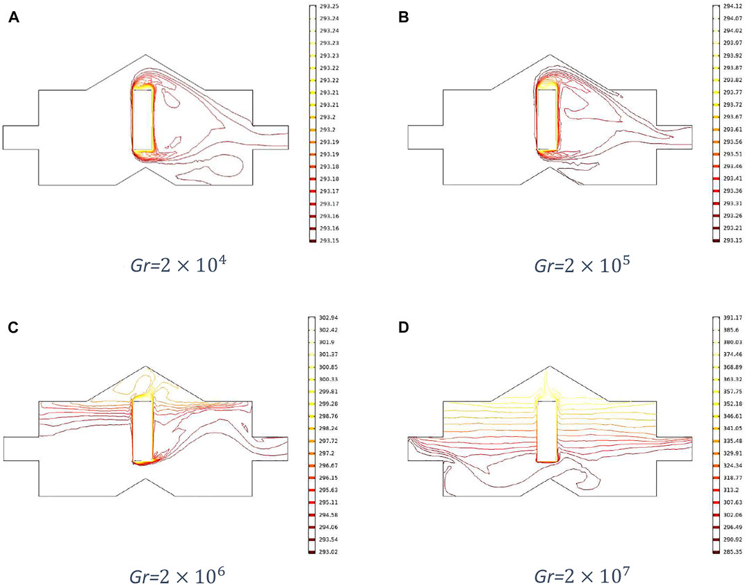
FIGURE 9. Isothermal contours at Re = 700 and at different Grashof numbers.
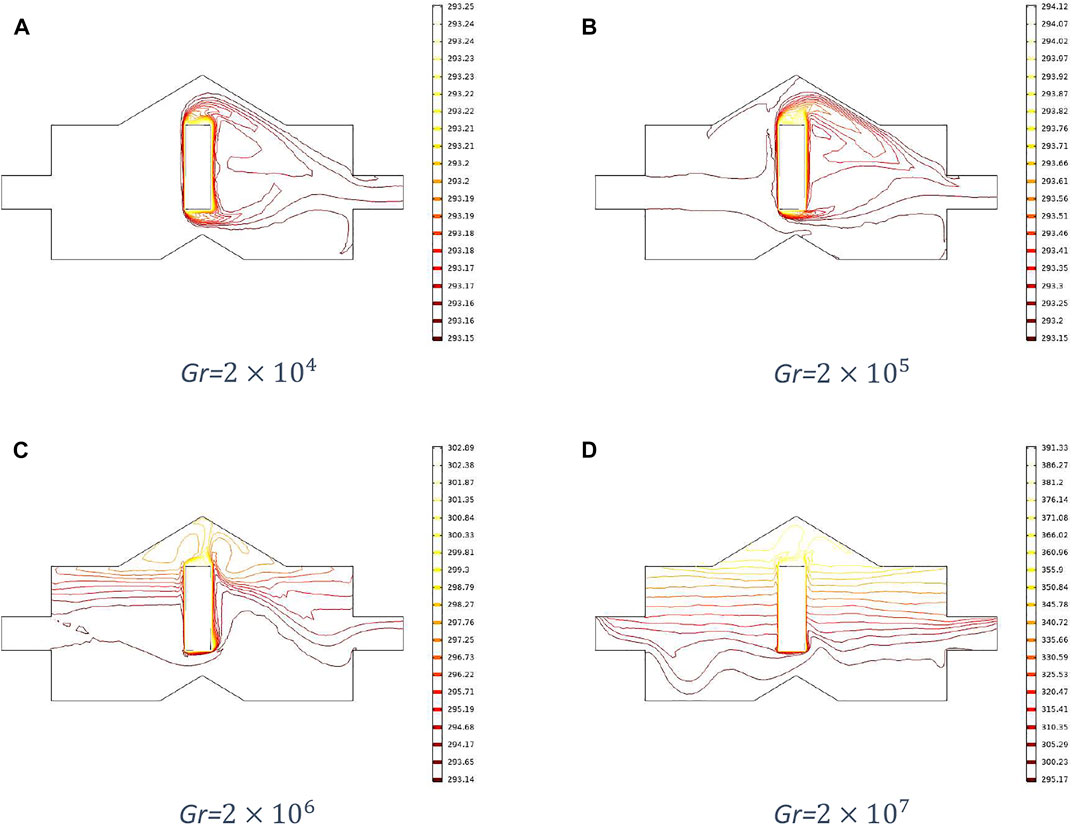
FIGURE 10. Isothermal contours at Re = 1,000 and at different Grashof numbers.
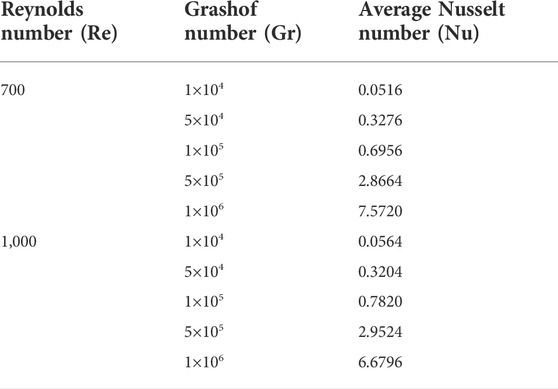
TABLE 2. Computation of Nusselt number for different Grashof numbers and Reynolds numbers.
In this paper, heat transfer has been investigated in laminar flow due to natural convection through the cavity formed by faults. The finite element method discretizes the prevailing equations. The discretized equations are dealt with through COMSOL Multiphysics. The computed results are displayed in the Discussion section. From the simulation of the flow, it is analyzed that the velocity of the fluid increases as the Grashof number increases, and it is greater below the metal piece due to the effect of the buoyancy force. Moreover, the Nusselt number also increases with the increased Grashof number. It is also concluded that the tensional fault zones formed by the energy accumulation of radioactive material disintegration cause the cavities which are responsible for the transportation of energy in the form of heat. There are many applications of the analysis of heat transfer and fluid flow characteristics of hydrothermal fluid through such cavities.
The raw data supporting the conclusion of this article will be made available by the authors, without undue reservation.
All authors have contributed to solve and write the paper under the supervision of SN.
The authors declare that the research was conducted in the absence of any commercial or financial relationships that could be construed as a potential conflict of interest.
All claims expressed in this article are solely those of the authors and do not necessarily represent those of their affiliated organizations, or those of the publisher, the editors, and the reviewers. Any product that may be evaluated in this article, or claim that may be made by its manufacturer, is not guaranteed or endorsed by the publisher.
1. Ohnaka M. The physics of rock failure and earthquakes, 148. Cambridge, England: Cambridge Univ. Press (2013).
3. Peacock DCP, Knipe RJ, Sanderson DJ. Glossary of normal faults. J Struct Geol (2000) 298:291–305. doi:10.1016/S0191-8141(00)80102-9
4. Hongsen X, Wei H, Wenge Z, Haifei Z, Genli S, Weiguo Z, et al. Materials science of the earth's interior (2000). Tokyo, Japan: Terra Sci. Publ. Company
5. Tingdong L. The uplifting process and mechanism of the Qinghai-Tibet plateau. Acta Geosci Sin (1995) 1:1–9.
6. Eldesoky IM, Abdelsalam SI, El-Askary WA, Ahmed MM. Concurrent development of thermal energy with magnetic field on a particle-fluid suspension through a porous conduit. Bionanoscience (2019) 9(1):186–202. doi:10.1007/s12668-018-0585-5
7. Abdelsalam SI, Bhatti MM. New insight into AuNP applications in tumour treatment and cosmetics through wavy annuli at the nanoscale. Sci Rep (2019) 9:260. doi:10.1038/s41598-018-36459-0
8. Abdelsalam SI, Bhatti MM. The study of non-Newtonian nanofluid with hall and ion slip effects on peristaltically induced motion in a non-uniform channel. RSC Adv (2018) 8:7904–15. doi:10.1039/c7ra13188g
9. Bhatti MM, Marin M, Zeeshan A, Ellahi R, Abdelsalam SI. Swimming of motile gyrotactic microorganisms and nanoparticles in blood flow through anisotropically tapered arteries. Front Phys (2020) 8:95. doi:10.3389/fphy.2020.00095
10. Sohail M, Naz R, Abdelsalam SI. Application of non-fourier double diffusions theories to the boundary-layer flow of a yield stress exhibiting fluid model. Physica A: Stat Mech its Appl (2020) 537:122753. doi:10.1016/j.physa.2019.122753
11. Abdelsalam SI, Bhatti MM. Anomalous reactivity of thermo-bioconvective nanofluid towards oxytactic microorganisms. Appl Math Mech (2020) 41(5):711–24. doi:10.1007/s10483-020-2609-6
12. Elmaboud YA, Abdelsalam SI, Mekheimer K, Vafai K. Electromagnetic flow for two-layer immiscible fluids. Eng Sci Technology Int J (2019) 22:237–48. doi:10.1016/j.jestch.2018.07.018
13. Mekheimera KS, Komyc SR, Abdelsalam SI. Simultaneous effects of magnetic field and space porosity on compressible Maxwell fluid transport induced by a surface acoustic wave in a microchannel. Chin Phys B (2013) 22(12):124702. doi:10.1088/1674-1056/22/12/124702
14. Abdelsalam SI, Vafai K. Combined effects of magnetic field and rheological properties on the peristaltic flow of a compressible fluid in a microfluidic channel. Eur J Mech - B/Fluids (2017) 65:398–411. doi:10.1016/j.euromechflu.2017.02.002
15. Akbar NS, Khan ZH. Effect of variable thermal conductivity and thermal radiation with CNTS suspended nanofluid over a stretching sheet with convective slip boundary conditions: Numerical study. J Mol Liq (2016) 222:279–86. doi:10.1016/j.molliq.2016.06.102
16. Rana S, Mehmood R, Akbar NS. Mixed convective oblique flow of a casson fluid with partial slip, internal heating and homogeneous heterogeneous reactions. J Mol Liq (2016) 222:1010–9. doi:10.1016/j.molliq.2016.07.137
17. Akbar NS, Tripathi D, Khan ZH, Beg OA. A numerical study of magnetohydrodynamic transport of nanofluids over a vertical stretching sheet with exponential temperature-dependent viscosity and buoyancy effects. Chem Phys Lett (2016) 661(16):20–30. doi:10.1016/j.cplett.2016.08.043
18. Ghaffari A, Mustafa I, Muhammad T, Altaf Y. Analysis of entropy generation in a power-law nanofluid flow over a stretchable rotatory porous disk. Case Stud Therm Eng (2021) 28:101370. doi:10.1016/j.csite.2021.101370
19. Mehryan SAM, Izadi M, Chamkha AJ, Sheremet MA. Natural convection and entropy generation of a ferrofluid in a square enclosure under the effect of a horizontal periodic magnetic field. J Mol Liq (2018) 263:510–25. doi:10.1016/j.molliq.2018.04.119
20. Dogonchi AS, Ismael MA, Chamkha AJ, Ganji DD. Numerical analysis of natural convection of Cu–water nanofluid filling triangular cavity with semicircular bottom wall. J Therm Anal Calorim (2019) 135(6):3485–97. doi:10.1007/s10973-018-7520-4
21. Chamkha AJ, Al-Naser H. Double-diffusive convection in an inclined porous enclosure with opposing temperature and concentration gradients. Int J Therm Sci (2001) 40(3):227–44. doi:10.1016/s1290-0729(00)01213-8
22. Tayebi T, Chamkha AJ. Free convection enhancement in an annulus between horizontal confocal elliptical cylinders using hybrid nanofluids. Numer Heat Transfer A: Appl (2016) 70(10):1141–56. doi:10.1080/10407782.2016.1230423
23. Tayebi T, Chamkha AJ. Entropy generation analysis due to MHD natural convection flow in a cavity occupied with hybrid nanofluid and equipped with a conducting hollow cylinder. J Therm Anal Calorim (2020) 139(3):2165–79. doi:10.1007/s10973-019-08651-5
24. Tayebi T, Chamkha AJ. Entropy generation analysis during MHD natural convection flow of hybrid nanofluid in a square cavity containing a corrugated conducting block. Int J Numer Methods Heat Fluid Flow (2019) 30(3):1115–1136. doi:10.1108/hff-04-2019-0350
25. Dogonchi AS, Armaghani T, Chamkha AJ, Ganji DD. Natural convection analysis in a cavity with an inclined elliptical heater subject to shape factor of nanoparticles and magnetic field. Arab J Sci Eng (2019) 44(9):7919–31. doi:10.1007/s13369-019-03956-x
26. Dogonchi AS, Nayak MK, Karimi N, Chamkha AJ, Ganji DD. Numerical simulation of hydrothermal features of Cu–H2O nanofluid natural convection within a porous annulus considering diverse configurations of heater. J Therm Anal Calorim (2020) 141(5):2109–25. doi:10.1007/s10973-020-09419-y
27. Selimefendigil F, Ismael MA, Chamkha AJ. Mixed convection in superposed nanofluid and porous layers in square enclosure with inner rotating cylinder. Int J Mech Sci (2017) 124:95–108. doi:10.1016/j.ijmecsci.2017.03.007
28. Dogonchi AS, Tayebi T, Chamkha AJ, Ganji DD. Natural convection analysis in a square enclosure with a wavy circular heater under magnetic field and nanoparticles. J Therm Anal Calorim (2020) 139(1):661–71. doi:10.1007/s10973-019-08408-0
29. Ghalambaz M, Jamesahar E, Ismael MA, Chamkha AJ. Fluid-structure interaction study of natural convection heat transfer over a flexible oscillating fin in a square cavity. Int J Therm Sci (2017) 111:256–73. doi:10.1016/j.ijthermalsci.2016.09.001
30. Alsabery AI, Ismael MA, Chamkha AJ, Hashim I, Abulkhair H. Unsteady flow and entropy analysis of nanofluids inside cubic porous container holding inserted body and wavy bottom wall. Int J Mech Sci (2021) 193:106161. doi:10.1016/j.ijmecsci.2020.106161
31. Tayebi T, Chamkha AJ. Magnetohydrodynamic natural convection heat transfer of hybrid nanofluid in a square enclosure in the presence of a wavy circular conductive cylinder. J Therm Sci Eng Appl (2020) 12(3):031009. doi:10.1115/1.4044857
32. Alsabery AI, Gedik E, Chamkha AJ, Hashim I. Impacts of heated rotating inner cylinder and two-phase nanofluid model on entropy generation and mixed convection in a square cavity. Heat Mass Transfer (2020) 56(1):321–38. doi:10.1007/s00231-019-02698-8
33. Dogonchi AS, Chamkha AJ, Ganji DD. A numerical investigation of magneto-hydrodynamic natural convection of Cu–water nanofluid in a wavy cavity using CVFEM. J Therm Anal Calorim (2019) 135(4):2599–611. doi:10.1007/s10973-018-7339-z
35. Cianfrini C, Corcione M, Dell’Omo PP. Natural convection in tilted square cavities with differentially heated opposite walls. Int J Therm Sci (2005) 44:441–51. doi:10.1016/j.ijthermalsci.2004.11.007
36. Nithyadevi N, Kandaswamy P, Sivasankaran S. Natural convection in a square cavity with partially active vertical walls: Time periodic boundary condition. Math.Probl Eng (2006) 2006:1-16. doi:10.1155/mpe/2006/23425
37. Rasoul J, Prinos P. Natural convection in an inclined enclosure. Int J Numer Methods Heat Fluid Flow (1997) 7:438–78. doi:10.1108/09615539710187783
38. Singh AK, Roy S, Basak T. Visualization of heat transport during natural convection in a tilted square cavity: Effect of isothermal and non isothermal heating. Numer Heat Transfer Part A: Appl (2012) 61:417–41. doi:10.1080/10407782.2012.654678
39. Yucel N, Turkoglu H. Natural convection in rectangular enclosures with partial heating and cooling. Warme- und Stoffubertragung (2019) 29:471–7. doi:10.1007/bf01539499
40. Aswatha B, Gowda CJG, Sridhara SN, Seetharamu KN. Buoyancy driven heat transfer in cavities subjected to thermal boundary conditions at bottom wall. J Appl Fluid Mech (2012) 5:43–53.
43. Papanastasiou T, Georgiou G, Alexandrou AN. Viscous fluid flow. Boca Raton, Florida: CRC Press (2021).
45. Nazeer M, Ali N, Javed T. Numerical simulation of MHD flow of micropolar fluid inside a porous inclined cavity with uniform and non-uniform heated bottom wall. Can J Phys (2018) 96(6):576–93. doi:10.1139/cjp-2017-0639
46. Ali N, Nazeer M, Javed T, Razzaq M. Finite element analysis of bi-viscosity fluid enclosed in a triangular cavity under thermal and magnetic effects. Eur Phys J Plus (2019) 134(1):2–20. doi:10.1140/epjp/i2019-12448-x
47. Nazeer M, Ali N, Javed T. Numerical simulations of MHD forced convection flow of micropolar fluid inside a right-angled triangular cavity saturated with porous medium: Effects of vertical moving wall. Can J Phys (2019) 97(1):1–13. doi:10.1139/cjp-2017-0904
48. Nazeer M, Ali N, Javed T. Effects of moving wall on the flow of micropolar fluid inside a right angle triangular cavity. Int J Numer Methods Heat Fluid Flow (2018) 28(10):2404–2422. doi:10.1108/hff-10-2017-0424
49. Ali N, Nazeer M, Javed T, Abbas F. A numerical study of micropolar flow inside a lid-driven triangular enclosure. Meccanica (2018) 53(13):3279–99. doi:10.1007/s11012-018-0884-5
50. Javed T, Mehmood Z, Siddiqui MA. Mixed convection in a triangular cavity permeated with micropolar nanofluid-saturated porous medium under the impact of MHD. J Braz Soc Mech Sci Eng (2017) 39(10):3897–909. doi:10.1007/s40430-017-0850-5
51. Javed T, Mehmood Z, Pop I. MHD-mixed convection flow in a lid-driven trapezoidal cavity under uniformly/non-uniformly heated bottom wall. Int J Numer Methods Heat Fluid Flow (2017) 27(6):1231–1248. doi:10.1108/hff-01-2016-0029
52. Javed T, Mehmood Z, Siddiqui MA, Pop I. Effects of uniform magnetic field on the natural convection of Cu–water nanofluid in a triangular cavity. Int J Numer Methods Heat Fluid Flow (2017) 27(2):334–357. doi:10.1108/hff-10-2015-0448
53. Javed T, Mehmood Z, Abbas Z. Natural convection in square cavity filled with ferrofluid saturated porous medium in the presence of uniform magnetic field. Physica B: Condensed Matter (2017) 506:122–32. doi:10.1016/j.physb.2016.11.008
54. Javed T, Siddiqui MA, Mehmood Z, Pop I. MHD natural convective flow in an isosceles triangular cavity filled with porous medium due to uniform/non-uniform heated side walls. Z Naturforschung A (2015) 70(11):919–28. doi:10.1515/zna-2015-0232
55. Temam R. Navier-Stokes equations: Theory and numerical analysis. Am Math Soc (2001) 343:28–29. doi:10.1090/chel/343
57. Turek S, Hron J, Razzaq M. Numerical benchmarking of fluid-structure interaction between elastic object and laminar incompressible flow. Dortmund, Germany: Universitätsbibliothek Dortmund (2010).
58. Razzaq M. Finite element simulation techniques for incompressible fluid structure interaction with applications to bio-engineering and optimization. PhD Thesis. Dortmund, Germany: TU Dortmund (2011).
Keywords: hydrothermal flow, heat transfer, finite element method, cavity access, Nusselt number (Nu)
Citation: Nadeem S, Akber R, Almutairi S, Ghazwani HA and Mahmoud O (2022) Numerical analysis of hydrothermal flow and heat transfer inside a cavity formed due to faults causing earthquakes. Front. Phys. 10:959168. doi: 10.3389/fphy.2022.959168
Received: 01 June 2022; Accepted: 27 June 2022;
Published: 22 August 2022.
Edited by:
Muhammad Mubashir Bhatti, Shandong University of Science and Technology, ChinaReviewed by:
Ali Chamkha, Kuwait College of Science and Technology, KuwaitCopyright © 2022 Nadeem, Akber, Almutairi, Ghazwani and Mahmoud. This is an open-access article distributed under the terms of the Creative Commons Attribution License (CC BY). The use, distribution or reproduction in other forums is permitted, provided the original author(s) and the copyright owner(s) are credited and that the original publication in this journal is cited, in accordance with accepted academic practice. No use, distribution or reproduction is permitted which does not comply with these terms.
*Correspondence: Sohail Nadeem, c29oYWlsQHFhdS5lZHUucGs=
Disclaimer: All claims expressed in this article are solely those of the authors and do not necessarily represent those of their affiliated organizations, or those of the publisher, the editors and the reviewers. Any product that may be evaluated in this article or claim that may be made by its manufacturer is not guaranteed or endorsed by the publisher.
Research integrity at Frontiers
Learn more about the work of our research integrity team to safeguard the quality of each article we publish.